APC BP1400 Datasheet

Category
Uninterruptible power supplies (UPSs)
Type
Datasheet

This manual is also suitable for

Contents/Sections/Indice
English ......................................................................................... 1
Français ...................................................................................... 19
Español ...................................................................................... 39
English
Please note:Please note:
Please note: The troubleshooting section (section 8) offers solutions for most of the difficulties you may en-
counter with this UPS. Before calling customer service, please have available your UPS’s serial number (see la-
bel on the rear of the UPS). A returned materials authorization (RMA) number is required for all return ship-
ments to APC. Do not send return shipments to APC without an RMA number. See section 9.
VV
VV
V
euilleeuille
euilleeuille
euille
z noter :z noter :
z noter :z noter :
z noter : La section «En cas de problème» (section 8) offre des solutions pour la plupart des difficultés
rencontrées lors de l’utilisation de l’onduleur. Si vous appelez notre service clientèle, veuillez avoir à portée
de main le numéro de série de votre onduleur (sur l’étiquette située sur le panneau arrière de l’onduleur). Un
numéro d’autorisation de retour de marchandise (RMA) est nécessaires pour tous les renvois à APC (les
conditons de service et d’intervention varient selon les pays. Veuillez contacter votre agence APC pour tout
renseignement sur les spécificités relatives à votre pays). Ne renvoyez aucun appareil à APC sans ce numéro.
Reportez-vous à la section 9.
Sírvase tomar nota:Sírvase tomar nota:
Sírvase tomar nota: La sección de detección y solución de problemas (sección 8) ofrece soluciones para la
mayoría de las dificultades que puede usted encontrar con este UPS. Antes de llamar a servicio al cliente,
sírvase tener disponible su número de serie del UPS (verlo en la etiqueta en la parte posterior del UPS). Se
requiere un número de autorización de devolución de materiales (RMA) para todos los envíos de devolución a
APC. No envíe despachos de devolución a APC sin un número RMA. Vea la sección 9.
Serial number:/Numéro de série:/Número de serie:
Return shipment addresses:
Adresse d’expédition des renvois :
Direcciones para devolver mercadería:
American Power Conversion Corporation
132 Fairgrounds Road
P. O. Box 278
West Kingston, Rhode Island 02892
USA
American Power Conversion Corporation
(A. P. C.) b. v.
Ballybritt Business Park
Galway
Ireland
Toll free technical support:
Numéro vert de l’assistance technique:
Número de teléfono sin costo para apoyo
técnico:
United States and Canada 1-800-800-4272
Ireland 1-800-702000
U. K. 0800-132990
Others/Autres/Otras:
+1 401 789 5735 (USA) or
+353 91 702020 (Ireland)
FrançaisEspañol
Entire contents copyright © 1995 American Power Conversion. All rights reserved; reproduction in whole or in part without
permission is prohibited. Back-UPS Pro is a trademark of APC. All other trademarks are the property of their respective owners.
Part Number 990-2012-C
Revised 10/95
1
English
1. Introduction ........................................................................... 1
2. Safety..................................................................................... 3
3. Presentation ........................................................................... 4
4. Installation ............................................................................. 5
5. Operation .............................................................................. 8
6. Alarms ................................................................................... 9
7. Options .................................................................................. 9
8. Troubleshooting ................................................................... 10
9. Service ................................................................................. 11
10. Battery Replacement ............................................................ 12
11. Storage ................................................................................ 14
12. Specifications ....................................................................... 15
13. How to Determine On-battery Run Time ............................... 17
1. Introduction
1.1 Thank you!
Thank you for selecting this uninterruptible power source (UPS). It is designed for many years of reliable,
maintenance-free service.
Important safety instructions!!
Please read this manual. It provides safety, installation, and operating instructions that should be followed
during installation and maintenance of the UPS and batteries. It will help you get the fullest performance
and service life from your UPS. This manual describes the inner workings of the UPS and how they relate to
providing superior protection from utility power problems such as blackouts, brownouts, sags, swells, EMI/
RFI noise, and surges. Also included are instructions for obtaining factory service, if necessary.
If you have a problem with the UPS, please refer to this manual before calling customer service. The
troubleshooting section (section 8) can help with most situations typically encountered when using the
UPS.
Please save the packaging materials!
The UPS’s shipping materials are designed with great care to provide protection during shipping. These ma-
terials are invaluable if you ever have to return the UPS for service. Damage sustained during transit is not
covered under the warranty.
2
1.2 Radio Frequency Interference
This equipment has been tested and found to comply with the limits for a Class B digital device, pursuant to
Part 15 of the FCC Rules and the Class B limits for radio noise emissions from digital apparatus set out in
the Radio Interference Regulations of the Canadian Department of Communications. These limits are de-
signed to provide reasonable protection against harmful interference in a residential installation. This
equipment generates, uses and can radiate radio frequency energy and, if not installed and used in accor-
dance with the instructions, may cause harmful interference to radio communications.
However, there is no guarantee that interference will not occur in a particular installation. If this equipment
causes interference to radio or television reception, which can be determined by turning the equipment off
and on, the user is encouraged to try to correct the interference by one or more of the following measures:
n reorient the receiving antenna
n increase the separation between the equipment and the receiver
n connect the equipment to an outlet on a circuit different from that to which the receiver is connected
n consult the dealer or an experienced radio/TV technician for help.
Shielded communications interface cables must be used with this product.
WW
WW
W
arar
arar
ar
ning:ning:
ning:ning:
ning: Changes or modifications to this unit not expressly approved by the party responsible for compli-
ance could void the user’s authority to operate the equipment.
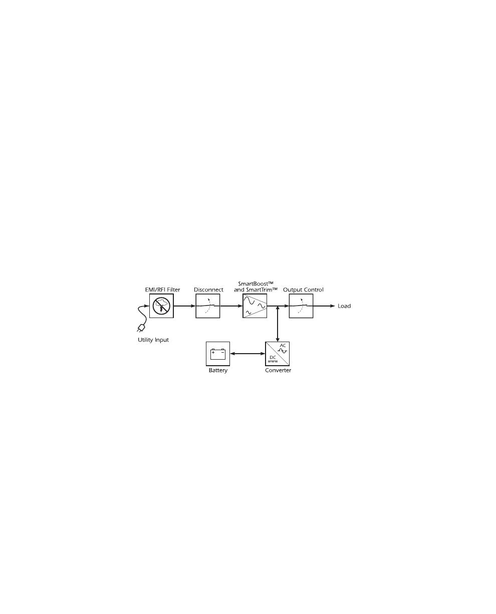
1.3 Theory of Operation
This high-performance, line-interactive, uninterruptible power source (UPS) provides clean, reliable, AC
power to computer systems — protecting them from power blackouts, brownouts, swells, sags, surges, and
interference.
Normally, the UPS operates “on-line,” supplying power from the
utility inpututility input
utility input to the
loadload
loadload
load (workstation,
server, or other device). The
concon
concon
con
vv
vv
v
erer
erer
er
terter
terter
ter circuitry is used to maintain an optimal float charge level on the
baba
baba
ba
t-t-
t-t-
t-
terter
terter
ter
yy
yy
y.
When the utility fails, the
disconnect disconnect
disconnect switch opens and the
con con
con con
con
vv
vv
v
erer
erer
er
terter
terter
ter supplies AC power to the
loadload
loadload
load. The
loads operate normally until shut down or until the battery is exhausted. The UPS automatically transfers
the load back to utility power and recharges the batteries when the line voltage returns to normal.
The UPS also provides surge protection and
EMI/RFI fEMI/RFI f
EMI/RFI fEMI/RFI f
EMI/RFI f
ilteringiltering
ilteringiltering
iltering, as well as
SmarSmar
SmarSmar
Smar
tBoost™ tBoost™
tBoost™ tBoost™
tBoost™ and
SmarSmar
SmarSmar
Smar
tTtT
tTtT
tT
rim™rim™
rim™rim™
rim™
automatic voltage regulation, which corrects high and low input voltage without drawing power from the
battery.
Output contrOutput contr
Output contr
olol
olol
ol uses the UPS’s remote interface to turn the load on or off, without disabling other UPS
functions.
3
English
1.4 Features
CellGuard™ Intelligent Battery Management
The UPS provides visual and audible indications of the batterys status including low battery and replace
battery conditions.
The UPS exercises the battery during its self-test, and will detect a weak battery before it is put into service.
The UPS normally performs a self-test at power up and every 14 days thereafter. Self-tests can also be con-
ducted manually with the on/off button at any time. See section 5.2.
The UPS features user-replaceable hot-swappable batteries. Batteries can be replaced without having to re-
move power from the loads or send the UPS in for service.
Power Management Software
This UPS offers advanced features when connected via the computer interface to a device using power man-
agement software.
Telephone Line and Network Surge Protection
This UPS provides advanced single telephone line or 10Base-T network surge suppression through the
modular connectors on the back panel. See section 4.
2. Safety
CAUTION!
n To reduce the risk of electric shock in conditions where load equipment grounding cannot be verified,
disconnect the UPS from the AC power outlet before installing a computer interface or accessory slot
signal cable. Reconnect the power cord only after all signaling connections are made.
n Connect the UPS to a two-pole, three-wire grounding AC power outlet. The receptacle must be con-
nected to appropriate branch protection (fuse or circuit breaker). Connection to any other type of re-
ceptacle may result in a shock hazard and violate local electrical codes.
n The UPS has an internal energy source (the battery).
TT
TT
T
he output mahe output ma
he output ma
y be enery be ener
y be enery be ener
y be ener
gizgiz
gizgiz
giz
ed wed w
ed wed w
ed w
hen the unit ishen the unit is
hen the unit is
not connected to an not connected to an
not connected to an
AA
AA
A
C poC po
C poC po
C po
ww
ww
w
er outlet.er outlet.
er outlet.
n To deenergize the outputs of the UPS:
1. If the UPS is on press the on/off button to switch the UPS off.
2. Disconnect the UPS from the AC power outlet.
3. To deenergize the UPS completely, disconnect the battery. See section 10.
Never install telephone wiring during a lightning storm.
n Use of this equipment in life support applications where failure of this equipment can reasonably be
expected to cause the failure of the life support equipment or to significantly effect its safety or effec-
tiveness is not recommended.
4
3. Presentation
3.1 Front panel
Press the
on/ofon/of
on/ofon/of
on/of
ff
ff
f button with the UPS plugged in to turn the UPS on or off. See Sec. 5.1.
On/ofOn/of
On/ofOn/of
On/of
ff
ff
f also activates the UPS’s self-test. See section 5.2.
The
oo
oo
o
vv
vv
v
erer
erer
er
loadload
loadload
load LED illuminates when the loads connected to the UPS exceed the UPS’s power capacity. See
section 6.2.
The
rr
rr
r
ee
ee
e
place baplace ba
place baplace ba
place ba
ttertter
ttertter
tter
yy
yy
y LED illuminates when the UPS’s battery is no longer useful and must be replaced. See
section 10.
The
on-baon-ba
on-baon-ba
on-ba
ttertter
ttertter
tter
yy
yy
y LED illuminates when the UPS is supplying battery power to the loads.
The
on-line on-line
on-line on-line
on-line LED means that filtered utility line is passing through the UPS to your equipment.
The
input poinput po
input poinput po
input po
ww
ww
w
er connectorer connector
er connector is a power cord with a NEMA 5-15P connector.
The
output pooutput po
output pooutput po
output po
ww
ww
w
erer
erer
er receptacles are NEMA 5-15R type.
The RJ-45/RJ-11 modular combination is used for
teletele
teletele
tele
phone/netwphone/netw
phone/netw
oror
oror
or
k surk sur
k surk sur
k sur
gg
gg
g
e pre pr
e pre pr
e pr
otectionotection
otectionotection
otection with single tele-
phone lines and 10Base-T networks. See section 4.5.
The
computer interfcomputer interf
computer interf
ace porace por
ace porace por
ace por
tt
tt
t is for UPS monitoring and control. See section 4.4.
5
English
3.2 Rear Panel
The
site wiring fsite wiring f
site wiring f
ault indicaault indica
ault indica
tortor
tortor
tor illuminates when the UPS is connected to an improperly wired AC power
outlet. See section 4.9.
The
input cirinput cir
input cirinput cir
input cir
cuit brcuit br
cuit brcuit br
cuit br
eakeak
eakeak
eak
erer
erer
er trips when loads exceed the UPS’s capacity. The resettable center plunger of the
circuit breaker extends when tripped.
4. Installation
Please fill out and return the warranty registration card now.
4.1 Inspection
Inspect the UPS upon receipt. Notify the carrier and dealer if there is damage. The packaging is recyclable;
save it for reuse or dispose of it properly.
4.2 Placement
Install the UPS in a protected area with adequate air flow that is free of excessive dust. Do not operate the
UPS where the temperature and humidity is outside the specified limits. See section 12. Allow the UPS to
come to room temperature before continuing.
6
4.3 Protection Strategies
This UPS provides high performance power line protection to the loads. There are, however, other potential
entry points for damaging surges in information systems. These include serial ports (RS-232, RS-422, RS-
485, etc.), parallel ports, telephone lines, and LAN connections. These other entry points must be consid-
ered in developing a comprehensive protection strategy for your system. Contact your dealer or call the
number in the front of this manual for information on related products designed to accomplish total system
protection.
Sensitive information systems can be further safeguarded by following these guidelines:
Verify that all electrical outlets are properly grounded. See section 4.9.
Connect computer leads to a different electrical service branch than heavy motor loads like air condi-
tioners, copiers, refrigerators, and heavy industrial machinery.
Plug all power protection and computer equipment into outlets connected to the same service branch
(controlled by the same fuse or circuit breaker) where possible.
4.4 Connect Computer Interface (Optional)
Power management software and interface kits can be used with this UPS. Use only kits supplied or ap-
proved by the manufacturer. If used, connect the interface cable to the 9-pin computer interface port on the
back panel of the UPS. Secure the connector’s screws to complete the connection.
Note:Note:
Note:Note:
Note: Computer interface connection is optional. The UPS works properly without a computer interface
connection.
4.5 Connect Telephone/Network Surge Suppression (Optional)
Connect a single line telephone or a 10Base-T network cable into the telephone/network surge protection
sockets on the back of the UPS. The RJ-45/RJ-11 modular combination sockets accept all standard single
line telephone and 10Base-T connections. This connection will require another length of telephone cable
(supplied) or network cabling (not supplied) to complete the connection.
Note:Note:
Note:Note:
Note: This connection is optional. It is not needed to use the UPS.
4.6 Connect to Utility
Plug the UPS into a two-pole, three-wire, grounded receptacle only. Avoid using extension cords and
adapter plugs.
7
English
4.7 Charge the battery
The UPS charges its battery whenever it is connected to utility power. For best results, charge the battery for
4 hours before use. It is acceptable to use the UPS without first charging the battery, but on-battery run
time may be reduced until the battery charges.
4.8 Connect the Loads
Plug the loads into the output connectors on the rear of the UPS. To use the UPS as a master on/off switch,
make sure that all of the loads are switched on.
Caution:Caution:
Caution:Caution:
Caution: Do not connect a laser printer to the UPS along with other computer equipment unless the UPS is
rated 1400 VA. A laser printer periodically draws significantly more power than when idle, and may over-
load the UPS. Verify that the UPS can support the loads when the printer is in full operation (printing).
Test the system with all loads operating to make sure that the UPS is not overloaded. See section 6.2.
4.9 Check the Site Wiring Fault Indicator
After plugging in the loads and the UPS, check the site wiring fault indicator on the rear panel. See section
3.2 for the location of the indicator on the back panel. It lights if the UPS is plugged into an improperly
wired AC power outlet. Wiring faults detected include missing ground, hot-neutral polarity reversal, and
overloaded neutral circuit.
Caution:Caution:
Caution:Caution:
Caution: If the UPS indicates a site wiring fault, get a qualified electrician to correct the building wiring.
4.10 Plug and Play
This UPS provides optional Plug and Play installation with those computers and operating systems that
support it. If you have purchased a Plug and Play UPS, a software and cable package will be included with
the unit. See the documentation included in the package for more information.
8
5. Operation
5.1 Switch On — Switch Off
With the UPS plugged in, press and release the on/off button to supply power to the loads. The loads are
immediately powered while the UPS performs a self-test. See section 5.2. Press and release the button again
to turn off power to the loads. It may be convenient to use the UPS as a master on/off switch for the pro-
tected equipment.
Note: The UPS is on (the internal processor is operating) whenever it is plugged in and utility voltage is
present. Even when switched off the UPS maintains the battery charge.
5.2 Self-test
The UPS performs a self-test automatically when turned on and every two weeks. Automatic self-test eases
maintenance requirements by eliminating the need for periodic manual self-tests.
During the self-test, the UPS briefly operates the loads on-battery. If the UPS passes the self-test, it returns
to on-line operation.
If the UPS fails the self-test it immediately returns to on-line operation and lights the replace battery LED.
The loads are not affected. Recharge the battery overnight and perform the self-test again. If the replace bat-
tery LED is still on, see section 10 for information on replacing the battery.
It is possible to perform a manual self-test at any time. To start a self-test:
PrPr
PrPr
Pr
essess
essess
ess and
hold hold
hold hold
hold the on/off button until the UPS beeps twice (about 2 seconds).
RR
RR
R
eleaseelease
eleaseelease
elease the on/off button to start the self-test.
5.3 Shutdown Mode
If there is no utility power present, external devices (e. g., servers) connected to the computer interface can
command the UPS to shut down. This is normally done to preserve battery capacity after the graceful shut-
down of protected PC devices. In shutdown mode the UPS stops supplying power to the load, waiting for
the return of utility power. The UPS alternately illuminates the upper front panel LED indicators in shut-
down mode.
9
English
5.4 Cold Start
When the UPS is off and there is no utility power, it is possible to cold start the UPS to apply power to the
loads from the UPS’s battery.
PrPr
PrPr
Pr
essess
essess
ess and
hold hold
hold hold
hold the on/off button until the UPS beeps twice (about two seconds).
RR
RR
R
eleaseelease
eleaseelease
elease the on/off button to start the UPS.
Note:Note:
Note:Note:
Note: Cold start is not a normal operating condition. On-battery and low battery alarms work as described
in section 6.
6. Alarms
6.1 On Battery
In on-battery operation, the on-battery LED illuminates and the UPS sounds an audible alarm consisting of
four beeps every 30 seconds. The alarm stops when the UPS returns to on-line operation.
6.2 Overload
When the UPS is overloaded (i. e., when the connected loads exceed maximum listed in section 12) the
overload LED illuminates and the UPS emits a sustained tone. The alarm remains on until the overload is
removed. Disconnect nonessential load equipment from the UPS to eliminate the overload. The UPS tests
for overloads when operating on-battery and when performing self-tests.
6.3 Replace Battery
If the battery fails a self test, the UPS emits short beeps for one minute and the Replace Battery LED illumi-
nates. The UPS repeats the alarm every five hours. After one week, the alarm becomes continuous. Perform
the self-test procedure in Section 5.2 to confirm replace battery conditions. The alarm stops when the bat-
tery passes the self-test.
6.4 Low Battery
On-battery, when the energy reserve of the battery runs low, the UPS beeps continuously until the UPS
shuts down from battery exhaustion or returns to on-line operation.
7. Options
7.1 Interface kits
For computer systems that have built-in UPS monitoring features, a series of interface kits are available to
connect the UPS to your system. Each kit includes the appropriate interface cable to convert the UPS status
signals into signals your system recognizes (use only factory supplied or authorized UPS monitoring
cables). See your dealer or call the number at the front of this manual for more information.
10
7.2 Wall Mount Bracket
A special wall mount bracket is available for this UPS. See your dealer or call the number at the front of this
manual for more information.
8. Troubleshooting
Problem Possible Cause Solution
UPS will not turn on.
On/Off button not pushed.
Press the On/Off button to power the UPS and
the load.
UPS input circuit breaker
tripped.
Reduce the load on the UPS by unplugging
equipment and reset the circuit break er by
pressing the plunger back in.
Very low or no utility voltage.
Check the AC power supply to the UPS with a
table lamp. If very dim or off, have the utility
voltage checked.
UPS will not turn on or off.
Computer interface or
accessory problem.
Disconnect the computer interface or accessory. If
the UPS now works normally, check the interface
cable, the attached computer, and the accessory.
UPS operates on-battery even
though normal line voltage is
thought to exist.
UPS's input circuit breaker
tripped.
Reduce the load on the UPS by unplugging
equipment and reset the circuit break er by
pushing the plunger back in.
UPS beeps occasionally. Normal UPS operation. None. The UPS is protecting the load.
UPS does not provide
expected back up time.
The UPS's battery is weak due
to recent outage or is near the
end of its service life.
Charge the battery. The UPS's batteries require
recharging after an extended outage. Batteries ag
e
faster when put into service often and when
operated at elevated temperatures. If the battery i
s
near the end of its service life, consider replacing
the battery even if the replace battery indicator is
not yet lit.
Top front panel indicators
flash alternately.
The UPS has been shut down
by the UPS interface kit.
None. The UPS will restart automatically when
utility power returns.
All indicators are flashing
(except On-Battery
indicator).
Internal UPS fault.
Do not attempt to use the UPS. Turn the UPS off
and have it serviced immediately.
The UPS operates normally,
but the Site Wiring Fault
indicator is lit.
Building wiring error such as
missing ground or hot to
neutral wire reversal.
Have a qualified electrician correct the building
wiring.
11
English
Problem Possible Cause Solution
All indicators are off and
the UPS is not operating.
The UPS is shut down an d t he
battery is discharged from an
extended power outage.
None. The UPS will return to normal operation
when the power is restored and the battery has a
sufficient charge.
The replace battery light
is illuminated.
Weak batteries.
Allow the batteries to recharge for at least four
hours. If the problem persists after recharging,
replace the batteries. See section 10.
Replacement batteries not
conne cte d pr ope r ly.
Confirm the battery connections. See section 10.
9. Service
If the UPS requires service:
1. Use the troubleshooting section (section 8) to eliminate common problems.
2. Verify that no circuit breakers are tripped. A tripped circuit breaker is the most common UPS problem!
3. Go to section 5.2 and perform a manual self-test to check the battery.
4. If the problem persists, see the front of this manual for the correct telephone number and call cus-
tomer service. If customer service is not available in your area, call the dealer that sold the UPS. Note
the model number of the UPS, the serial number, and the date purchased. A technician will ask you to
describe the problem and try to solve it over the phone, if possible. If this is not possible the technician
will issue an RMA#. If the UPS is under warranty, repairs are free. If not, there will be a charge for re-
pair.
5. Pack the UPS in its original packaging. If the original packing is not available, ask customer service
about obtaining a new set. It is important to pack the UPS properly to avoid damage in transit. Never
use styrofoam beads for packaging. Damage sustained in transit is not covered under warranty. Include
a letter with your name, RMA#, address, copy of the sales receipt, description of the trouble, your day-
time phone number, and a check (if necessary).
6. Mark the RMA# on the outside of the package. The factory cannot accept any package without this
marking.
7. Return the UPS by insured, prepaid carrier to the address at the front of this manual.
12
10. Battery Replacement
This UPS has an easy to replace hot-swappable battery. Please read section 10.1 before performing the pro-
cedure in sections 10.3 or 10.4.
10.1 Warning
n This Uninterruptible Power Source (UPS) contains potentially hazardous voltages. Do not attempt to
disassemble the unit beyond the battery replacement procedures below. Except for the battery, the unit
contains no user serviceable parts. Repairs are performed only by factory trained service personnel.
n The batteries in this UPS are recyclable. Dispose of the batteries properly. The batteries contain lead
and pose a hazard to the environment and human health if not disposed of properly. Refer to local
codes for proper disposal requirements or return the battery to a factory authorized service center. See
the instructions with the new battery for more information.
CACA
CACA
CA
UTION—UTION—
UTION—UTION—
UTION—Do not dispose of batteries in a fire. The batteries may explode.
CACA
CACA
CA
UTION—UTION—
UTION—UTION—
UTION—Do not open or mutilate batteries. They contain an electrolyte which is toxic and harmful to
the skin and eyes.
CACA
CACA
CA
UTION—UTION—
UTION—UTION—
UTION—To avoid personal injury due to energy hazard, remove wrist watches and jewelry such as rings
when replacing the batteries. Use tools with insulated handles.
CACA
CACA
CA
UTION—UTION—
UTION—UTION—
UTION—Replace batteries with the same number and type of batteries as originally installed in the
UPS.
10.2 Replacement Batteries
See your dealer or call the number at the front of this manual for information on battery recycling and re-
placement battery kits.
13
English
10.3 Battery Replacement Procedure (280, 420 and 650 VA
models)
Note:Note:
Note:Note:
Note: Please read the cautions in section 10.1.
Battery replacement is a safe procedure, isolated from electrical hazards. You may leave the UPS and loads
on for the following procedure.
1. Lay the UPS on its left side. Remove the two screws holding on the battery door and
openopen
openopen
open the door.
Note:Note:
Note:Note:
Note: The battery door may need to be pulled away from the hinges somewhat to allow it to become
fully swung open.
2. Gently
pullpull
pullpull
pull out the battery by grasping the white tab.
3.
DisconnectDisconnect
Disconnect the two wires connecting the battery to the UPS. Loosen the wires by gently wiggling them
while pulling straight back from the battery connector.
4.
ConnectConnect
ConnectConnect
Connect the new battery in place of the old.
Note:Note:
Note:Note:
Note: Small sparks at the battery connections are normal
during connection.
5.
RR
RR
R
ee
ee
e
placeplace
placeplace
place the new battery in the UPS. Use care to avoid pinching the wires.
6.
CloseClose
CloseClose
Close the battery compartment door and replace the screws.
7.
DisposeDispose
DisposeDispose
Dispose of the old battery properly at an appropriate recycling facility or return it to the supplier in the
packing material for the new battery. See the new battery instructions for more information.
14
10.4 Battery Replacement Procedure (1000 and 1400 VA models)
Note:Note:
Note:Note:
Note: Please read the cautions in section 10.1.
Battery replacement is a safe procedure, isolated from electrical hazards. You may leave the UPS and loads
on for the following procedure.
1. Grasp the top of the front cover and
tilttilt
tilttilt
tilt it out and down.
2.
UnhookUnhook
UnhookUnhook
Unhook the bottom of the cover from the chassis and lift it upward to expose the battery door. Be care-
ful not to strain the ribbon cable. Do not touch the exposed printed circuit board.
3.
FF
FF
F
oldold
oldold
old the front cover on top of the UPS as shown.
4. Use a screwdriver or a coin to
rr
rr
r
emoemo
emoemo
emo
vv
vv
v
ee
ee
e the two battery door screws and open the door.
5. Grasp the tab and gently
pullpull
pullpull
pull the battery out of the UPS.
6.
Disconnect Disconnect
Disconnect the battery leads.
7.
ConnectConnect
ConnectConnect
Connect the battery leads to the new battery.
Note:Note:
Note:Note:
Note:
Small sparks at the battery connectors are normal
during battery connection.
8. Slide the battery into the UPS, close the battery door, replace the battery compartment screws, and re-
place the front cover.
9.
DisposeDispose
DisposeDispose
Dispose of the old battery properly at an appropriate recycling facility or return it to the supplier in the
packing material for the new battery. See the new battery instructions for more information.
11. Storage
11.1 Storage conditions
Store the UPS covered and upright in a cool, dry location, with its battery fully charged. Before storing,
charge the UPS for at least 4 hours. Disconnect any cables connected to the computer interface port to
avoid unnecessarily draining the battery.
15
English
11.2 Extended storage
During extended storage in environments where the ambient temperature is –15 to +30 °C (+5 to +86 °F),
charge the UPS’s battery every 6 months.
During extended storage in environments where the ambient temperature is +30 to +45 °C
(+86 to +113 °F), charge the UPS’s battery every 3 months.
12. Specifications
280 VA 420 VA 650 VA 1000 VA 1400 VA
Acceptable input voltage 0 - 160 VAC
Input voltage (on-line operation) 92-150 VAC
Output voltage 103-132 VAC
Nominal input frequency 50 or 60 Hz, autosensing
Input Protection Resettable circuit breaker
Frequency limits (on-line operation) 50 or 60 Hz, ±5%
Transfer time 2 ms typical, 4 ms maximum
Maximum load
280 VA 180
W
420 VA 260
W
650 VA
410 W
1000 VA 670
W
1400 VA 950
W
On-battery output voltage 115 VAC
On-battery frequency 50 or 60 Hz, ±0.1 Hz
On-battery waveshape Stepped sine-wave Trapezoid
Protection Overcurrent and short-circuit protected, latching shutdown on overload.
Surge energy rating (one time, 10/1000 µs
waveform)
320 J
Surge current capability (one time, 8/20 µs
waveform)
13kAmps maximum
Surge response time
0 ns (instantaneous) normal mode;
<5 ns common mode
Surge voltage let-through (percentage of
applied ANSI C62.41 Cat. A ±6 kV test
waveform)
<5% <0.5%
Noise Filter Normal and common mode EMI/RFI suppression, 100 kHz to 10 MHz
Battery type Spill proof, maintenance free, user replaceable, sealed lead-acid
Typical battery life
3 to 6 years, depending on number of discharge cycles and ambient
temperature
Typical recharge time 2 to 5 hours from total discharge
Telephone line surge protection, 1.2 µs/50
waveform.
±6kV peak
16
280 VA 420 VA 650 VA 1000 VA 1400VA
10Base-T surge protection let-through
(as a percentage of an applied ±6 kV
1.2/50 µs, 125 A 8/20 µs test)
<5%
Telephone line surge protection
let-through (as a percentage of an applied
±6 kV 1.2/50 µs, 500 A 8/20 µs test)
<1%
Operating temperature 0 to +40 ºC (+32 to +104 ºF)
Storage temperature (see section 11) -15 to +45 ºC (+5 to +113 ºF)
Operating and storage relative humidity 0 to 95%, non-condensing
Operating elevation 0 to +3,000 m (0 to +10,000 ft)
Storage elevation 0 to +15,000 m (0 to +50,000 ft)
Electromagnetic immunity IEC 801-2 level IV, 801-4 level IV, 801-5 level III
Audible noise at 1 m (3 ft) <45 dBA <50 dBA
Size (H x W x D)
Model 280, 420
16.8 x 11.9 x 36.8 cm
(6.6 x 4.7 14.5 in.)
16.8 x 11.9 x
36.8 cm (6.6
x 4.7 x 14.5
in.)
21.6 x 17 x 43.9 cm (8.5
x 6.7 x 17.3 in.)
Model 280B, 420B
15 x 8.6 x 33.8 cm
(5.9 x 3.4 x 13.3 in.)
Weight - net (shipping)
Model 280
7.2 (8.5) kg;
15.9 (18.7)
lb.
Model 420
7.8 (9.1)
kg
17.2 (20.0)
lb.
10.9 (12.2)
kg;
24.0 (26.8)
lb.
19.3 (21.3)
kg;
42.5 (47) lb.
24.1 (26.1)
kg;
53 (57.5)
lb.
Model 280B
6.6 (7.5) kg;
14.5 (16.6)
lb.
Model 420B
7.2 (8.1) kg;
15.9 (18) lb.
Safety and approvals UL 1778, UL 497A, CSA 22.2
EMC verification FCC/DOC Class B certified
12. Specifications
(Continued)
17
English
13. How to Determine On-battery Run Time
Knowing the on-battery run time of the UPS is an important part of UPS use, especially in situations where
the protected device uses an operating system that requires some time to gracefully shut down.
1. To calculate the on-battery run time first determine the total load protected by the UPS in Volt-Amps.
Obtain load figures from either the labelling on the protected equipment or the accompanying litera-
ture. For loads specified in watts, multiply the specified figure by 1.4. For loads specified in Amps, mul-
tiply the specified figure by 120.
2. Add the individual loads to determine the total load.
3. Compare the total load of your system to the run time table below.
Typical On-Battery Run Time Versus Load, in Minutes
Load 280 VA 420 VA 650 VA 1000 VA 1400 VA Load 650 VA 1000 VA 1400 VA
50 VA 35 41 90 167 306 500 VA 7.2 14 29
75 VA 25 27 64 125 236 550 VA 6.5 13 26
100 VA 18 21 49 98 190 600 VA 5.8 11 23
150 VA 12 14 29 64 133 700 VA - 9 19
200 VA 8 10 22 47 99 800 VA - 7.7 16
250 VA 6 7.5 17 35 74 900 VA - 6.6 13
300 VA - 6.2 14 27 60 1000 VA - 5.8 11
350 VA - 5.1 11 22 50 1200 VA - - 8.8
400 VA - 4.3 9.3 19 42 1400 VA - - 7.2
450 VA - - 8.2 17 35
English
Français
Español
The world’s most reliable
power protection
  • Page 1 1
  • Page 2 2
  • Page 3 3
  • Page 4 4
  • Page 5 5
  • Page 6 6
  • Page 7 7
  • Page 8 8
  • Page 9 9
  • Page 10 10
  • Page 11 11
  • Page 12 12
  • Page 13 13
  • Page 14 14
  • Page 15 15
  • Page 16 16
  • Page 17 17
  • Page 18 18
  • Page 19 19
  • Page 20 20
  • Page 21 21
  • Page 22 22
  • Page 23 23
  • Page 24 24
  • Page 25 25
  • Page 26 26
  • Page 27 27
  • Page 28 28
  • Page 29 29
  • Page 30 30
  • Page 31 31
  • Page 32 32
  • Page 33 33
  • Page 34 34
  • Page 35 35
  • Page 36 36
  • Page 37 37
  • Page 38 38
  • Page 39 39
  • Page 40 40
  • Page 41 41
  • Page 42 42
  • Page 43 43
  • Page 44 44
  • Page 45 45
  • Page 46 46
  • Page 47 47
  • Page 48 48
  • Page 49 49
  • Page 50 50
  • Page 51 51
  • Page 52 52
  • Page 53 53
  • Page 54 54
  • Page 55 55
  • Page 56 56
  • Page 57 57
  • Page 58 58
  • Page 59 59
  • Page 60 60
  • Page 61 61
  • Page 62 62
  • Page 63 63
  • Page 64 64
  • Page 65 65
  • Page 66 66

APC BP1400 Datasheet

Category
Uninterruptible power supplies (UPSs)
Type
Datasheet
This manual is also suitable for

Ask a question and I''ll find the answer in the document

Finding information in a document is now easier with AI

in other languages