Page is loading ...

R10 CEILING SUBWOOFER INSTALL GUIDE

BLACK R10 INSTALL GUIDE BLACK R10 INSTALL GUIDE
Preparation:
Installation:
Tools For Installation Speaker Wire Guide
Considerations
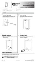
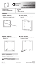
Cut Out
- Pencil
- Drill
- Tape Measure
- Wire Cutter
- Phillips Screwdriver
- Utility Knife
- Safety Eye Wear
- Gloves
- Sandpaper
- Where is the best place to install the speakers?
- Where do the speakers sound the best?
- Separate the speakers 6 - 10 feet apart.
- If you intend to paint the grilles, do so before installation.
NOTE: This is the most important part of the entire installation.
If you are not certain whether any obstructions exist behind the
desired mounting area, you should start by cutting a small hole in
the center of your penciled mounting hole with a drywall saw.
Trace along the included template. Cut along the traced line using a
drywall saw or rotary drill. Use a piece of sandpaper to sand down the
cut out edge for a smoother contour. (See Diagram 1.)
18AWG minimum - for distances up to …………………. 10 ft
16AWG - from …………………………………..…... 10 to 50 ft
14AWG - from …………………………………...… 50 to 100 ft
Diagram 1:
Mounting
Connection
Tighten the mounting brackets by simply turning the screws on
the front of the speaker bafe slowly clockwise. The quick-turn
mounting system and frame will “sandwich” or clamp around the
dry-wall to hold the speaker securely in place once fully tightened
to the locked position.
(See Diagram 2.)
We recommend using a OSD SMP300 or SMP500 DSP Amplier.
When connecting any speakers to the amplier or receiver, always
make sure the power is off. Locate the connection terminals on the
back of your receiver or amplier. Always make sure to connect au-
dio out from the back of your receiver or amplier to the speakers.
(See Diagram 3.)
NOTE: Not all Amplier/Receivers can safely play more than one
pair of speakers at once. Please refer to your owner’s manual for
impedance and wattage compatibility.
Open PositionLocked Position
Subwoofer Amplier
Diagram 2:
Diagram 3:
SMP300 / SMP500 DSP
- IN +
- IN +
NCR10 Bracket Installation - New Construction
NCR10 Construction Bracket Recommended:
NCR10 Bracket Installation - Retrot
Diagram 1:
Diagram 2:
Diagram 3:
The NCR10 is designed for new construction or retrot applications with it’s unique folding design. The NCR10 may be installed prior to
drywall or after across joists (from 16"- 24" on-center) where a speaker will be mounted.
1. Find the joist nearest the desired speaker mounting location. If you
need to align the speaker to some other object or molding in the room,
be sure to consider the size of the bafe ange which extends beyond
the mounting hole.
2. Line up the bottom of one of the mounting bars with the bottom of
the joist. This will place the screw holes in an “L” position, ush with
the side of the joist, and the mounting ring “lip” will be facing down-
ward. Attach the mounting bar to the joist using appropriate wood
screws.
3. Make sure that the mounting ring is in a perfectly circular shape
(see Diagram 1.) by opening the bracket until the arms come in con-
tact with the stoppers. Then, lineup the bottom of the other mounting
bar with the bottom of the same joist. Attach the mounting bar to the
joist using appropriate wood screws.
4. Extend both mounting bars to reach the opposite joist, then line up
the bottoms of each mounting bar with the bottom of the joist. Attach
the mounting bar to the joist using appropriate wood screws.
5. Adjust the position of the mounting ring between the joists, grab
both sides of the mounting ring, where it connects to the mounting bar,
then move the mounting ring to the desired position.
6. The protruding lip of the mounting ring will force the drywall install-
ers to hang the drywall with an appropriate hole cut out around the
mounting ring lip. After the drywall is hung and nished, the speakers
are then easily installed.
1. Find the joist nearest the desired speaker mounting location.
If you need to align the speaker to some other object or molding
in the room, be sure to consider the size of the bafe ange
which extends beyond the mounting hole.
2. Mark the hole using the speakers cut out template. Position
the template in the desired and pencil an outline on the ceiling.
3. Cut the hole. CAUTION: If you are not certain whether any
obstructions exist behind the mounting area, you should start by
cutting a small hole in the center of the penciled template outline
with a drywall saw, cutting at a 45° angle towards the inside of
the hole. (see Diagram 3.) Cutting a small hole at this angle will
make drywall repair easier if needed. If there are no obstructions
cut the nished hole at a 90° angle to the ceiling surface.
4. Collapse the mounting ring and the mounting bars to com-
press the bracket to it’s smallest shape (see Diagram 2.)
5. With the mounting lip facing downward, insert the bracket into
the ceiling cavity through the speaker cutout hole previously cut
in the drywall.
6. Make sure that the mounting ring is in a perfectly circular
shape by opening the bracket until the arms come in contact
with the stoppers, then set it into the ceiling hole. Push one of
the mounting bars L-shaped edges until it is ush with the joist,
and the bottom of the mounting bar lines up with the bottom of
the joist. Attach the mounting bar to the joist using appropriate
wood screws.
7. Push the other mounting bar L-shaped edge until it is ush
with the same joist, and the bottom of the mounting bar lines up
with the bottom of the joist. Attach the mounting bar to the joist
using appropriate wood screws.
8. Extend both mounting bars to reach the opposite joist, then
line up the bottoms for each mounting bar with the bottom of the
joist. Attach the mounting bar to the joist using appropriate wood
screws.

All Optimal Speaker Design speaker products have Limited Lifetime Warranty against defects in materials and workmanship. Proof
of purchase must accompany all claims. During the warranty period Optimal Speaker Design will replace any defective part and
correct any defect in workmanship without charge for either parts or labor Optimal Speaker Design may replace returned speakers
with a product of equal value and performance. In such cases, some modication to the mounting may be necessary and are not
Optimal Speaker Designs responsibility.
For this warranty to apply, the unit must be installed and used according to its written instructions. If necessary, repairs must be
performed by Optimal Speaker Design. The unit must be returned to Optimal Speaker Design at the owner’s expense and with
prior written permission. Accidental damage and shipping damage are not considered defects, nor is damaged resulting from
abuse or from servicing performed by an agency or person not specically authorized in writing by Optimal Speaker Design
Optimal Speaker Design sells products only through authorized dealers and distributors to ensure that customers obtain proper
support and service. Any Optimal Speaker Design product purchased from an unauthorized dealer or other source, including
retailers, mail over dealers and on-line sellers will not be honored or serviced under existing Optimal Speaker Design warranty
policy. Any sale of product by an unauthorized source or other manner not authorized by Optimal Speaker Design shall void the
warranty on the applicable product.
Damage to or destruction of components due to application of excessive power voids the warranty on those parts. In these cases,
repairs will be made on the basis of the retail value of the parts and labor. To return for repairs, you must email customer service
at [email protected] for a Returned Merchandise Authorization (RMA) number# then the unit must be shipped to
Optimal Speaker Design at the owner’s expense, along with a note explaining the nature of service required. Be sure to pack the
speaker(s) in a corrugated container with at least 3 inches of resilient material to protect the unit from damage in transit.
This Warranty Does Not Cover: Damage caused by abuse, accident, misuse, negligence, or improper operation (installation) •
Any products that have been altered or modied • Any product whose identifying number of decal, serial #, etc. has been altered,
defaced or removed • Normal wear and maintenance.
WARRANTY
WARRANTY
Black R10 Manual 9/20
Specications
Type: Passive Ceiling Subwoofer
Woofer: 10" Long Excursion Graphite Cone
Power Handling: 200 Watts
Freq Response: 30 - 120Hz
Sensitivity: 92dB 1W/1m
Grille: Trimless Thin-Bezel held by Neo Magnets
Dimensions: 13
3
/
8
" x 6½"
Cut Out: 11
7
/
8
"
/