Clever by design, the KICKSPACE
®
unit fits neatly
within a unit plinth or floor cavity providing a fresh
thinking, innovative heating solution. Where traditional
radiators take up precious wall space and restrict
design possibilities, the KICKSPACE
®
heater allows
freedom to tailor your home around your lifestyle.
Central heating, electric and duo models available. All
units are now supplied complete with a white grille.
The KICKSPACE
®
can also be used alongside the
MYSON INNOKO towel rail to provide the perfect
drying and heating solution for any kitchen. For
information on the MYSON range of towel warmers
please contact Customer Services.
KICKSPACE
®
The space saving solution.
Before.
After.
06
KICKSPACE
®
KICKSPACE
®
works by drawing room air over the
heated fins of the unit heat exchanger and projecting
warm air back into the room. Controls are situated on
the front grille, with the unit having a choice of heating
fan speeds (winter setting) as well as a fan-only
(summer setting) operation. Alternatively, a remote
control wall switch can be fitted to central heating and
duo models for extra control and convenience.
Effective climate control.
KICKSPACE
®
07
08
KICKSPACE
®
The kitchen is often where space is most at a premium
and the KICKSPACE
®
can deliver the most benefits
but equally, the bathroom or hallway can offer
alternative applications. All versions, except the floor
model, are designed to be installed horizontally into
recessed locations. They require an adequate supply
of inlet air and the axis of the motor must remain
horizontal.
KICKSPACE
®
Applications.
KICKSPACE
®
Floor model.
KICKSPACE
®
09
The unit grille and remote wall switch can be
customised to suit any room décor with a variety of
metallic and colour finish options. The remote room
thermostat is supplied white as standard and is
suitable for the 500, 600 & 800 hydronic models.
Accessories.
Central Heating
500
600
800
Floor
600-12V
Electric
500E
600E
Duo
(Central Heating/Electric)
500 Duo
For technical information please refer to pages 17-21.
Model details
Grilles.
Remote wall switch.
Remote room thermostat.
System Design for Fan Convectors
Fan convectors are intended to be connected to central heating
systems in the same way as radiators, and offer advantages
and benefits not available from traditional emitters. To ensure
optimum fan convector performance, great care must be taken
to ensure that the choice of unit and the heating system design
are considered. The following factors must be taken into
consideration:
l
Fan convectors should only be used on closed
circulation, two pipe, pump assisted central heating systems.
l
Fan convectors should be correctly sized to match the heat
loss requirement of the room with the unit operating at its
lowest fan speed.
l
The heating system must be capable of providing
sufficient hot water through the heat exchanger. This
means that:
l
The minimum pipe size should be 15mm.
l
Fan convectors are not suitable for use on microbore
pipe-work.
l
Fan convectors are not suitable for one-pipe systems.
l
Where the unit is fitted onto a system with other
emitters, a separate circuit for the fan convector should
be considered to ensure an adequate water flow
through it.
l
The heating system water temperature must be greater
than 43°C in heating mode for the unit to operate
(lower temperatures possible for heat pump
applications on wall mounted units).
l
Optimum performance of the fan convector will
require effective balancing of the whole system.
l
Fan convectors should not be used to replace
radiators in existing systems unless pipe-work sizing,
system design and system balancing can guarantee an
adequate flow of water through the fan convector.
l
The maximum working pressure through the heat
exchanger is 10 bar (150 lb/in
2
). The maximum
allowable water temperature through the heat
exchanger is 90
o
C.
l
Wall mounted units should be mounted on a flat wall,
and stud or partition walls should be avoided to
minimise the possibility of noise transmission.
16
System Design for Fan Convectors
KICKSPACE
®
Product Range
Model Flexible Hoses* Electric Cable Transformer Fan Only Option
KICKSPACE
®
500 Supplied Supplied N/A Yes
KICKSPACE
®
600 Supplied Supplied N/A Yes
KICKSPACE
®
800 Supplied Supplied N/A Yes
KICKSPACE
®
Floor Supplied Supplied N/A Yes
Isolating Valves
(15mm)
2 metres
(mains fitted)
2 metres
(mains fitted)
2 metres
(mains fitted)
2 metres
(mains fitted)
Model Flexible Hoses* Electric Cable Transformer Fan Only Option
KICKSPACE
®
500E N/A N/A N/A Yes
KICKSPACE
®
600E N/A N/A N/A Yes
Isolating Valves
(15mm)
2 metres
(mains fitted)
2
1
/2 metres
(mains fitted)
Model Flexible Hoses* Electric Cable Transformer Fan Only Option
KICKSPACE
®
500 Duo Supplied Supplied N/A Yes
Isolating Valves
(15mm)
2 metres
(mains fitted)
Model Flexible Hoses* Electric Cable Transformer Fan Only Option
Supplied Supplied Yes
Isolating Valves
(15mm)
1 metre
(low voltage fitted)
Supplied
(external from product)
1 metre
(mains fitted)
KICKSPACE
®
600-12V
*750mm x 10mm bore, EPDM hoses, sheathed in AISI 304 stainless steel braid.
Please note that KICKSPACE
®
600E grilles are an integral part of the product and can not be changed.
KICKSPACE
®
Technical Information
17
Electric Product Range
Duo (Hydronic-Electric) Product Range
Low Voltage Hydronic Product Range
Hydronic Product Range
Hydronic (KICKSPACE
®
500, 600, 800, 600-12V)
Fan Speed - Normal/off/boost.
Summer/Winter - Fan only/heating option.
Hydronic Electric (KICKSPACE
®
500 Duo)
Summer/Off/Winter - Fan only/off/heating options.
System Selector - Central heating/electric heating.
Fan Speed - Normal/boost.
Electric (KICKSPACE
®
500E)
Summer/Off/Winter - Fan only/off/heating option.
Power Selector - 1kW or 2kW.
Fan Speed - Normal/boost.
Electric (KICKSPACE
®
600E)
Summer/Winter/Output.
KICKSPACE
®
Controls
KICKSPACE
®
Performance Data
Heat outputs tested in accordance with BS 4856 Part 1.
Flow Rate: 340 ltr/h (75 gal/h).
Flow Rate Correction Factors:
455 ltr/h (100 gal/h) multiply output by 1.03.
227 ltr/h (50 gal/h) multiply output by 0.96.
113 ltr/h (25 gal/h) multiply output by 0.85.
Duo (Hydronic/Electric) Heating Performance Data - Electric Mode
The unit will operate on either fan speed to provide 1kW of heating.
ltr/h
500 600 800 Floor 600-12V 500 Duo 500 600 800 Floor 600-12V 500 Duo
455 788 1046 911 448 1046 652 7.7 10.3 8.9 4.4 10.3 6.4
340 488 625 544 258 625 380 4.8 6.1 5.3 2.5 6.1 3.7
227 231 326 258 136 326 204 2.3 3.2 2.5 1.3 3.2 2.0
113 82 95 82 54 95 68 0.8 0.9 0.8 0.5 0.9 0.7
Approximate Hydraulic Resistance
18
KICKSPACE
®
Technical Information
Model
40° 45° 50° 55° 60° 40° 45° 50° 55° 60°
500
Normal 733 815 896 976 1056 2501 2781 3057 3331 3603
Boost 923 1044 1166 1289 1412 3150 3564 3980 4397 4817
600
Normal 890 1048 1213 1384 1562 3036 3575 4138 4723 5329
Boost 1279 1451 1625 1800 1977 4363 4952 5545 6143 6744
800
Normal 1396 1552 1707 1860 2012 4763 5296 5824 6346 6864
Boost 1738 1964 2192 2420 2649 5930 6702 7478 8257 9039
Floor
Normal 622 711 802 894 987 2122 2427 2736 3049 3366
Boost 1035 1178 1322 1468 1615 3531 4018 4510 5008 5510
Heat Output (watts) Heat Output (Btu/h)
Hydronic Heating Performance Data
Heat outputs tested in accordance with BS 4856 Part 1.
Hydronic Models
It is preferable to select the model with an output capable of
maintaining the calculated heat losses of the room when
operating at normal speed. This will enable the boost fan speed
and the higher temperature differences to be used to greater
advantage for rapid warming of the room from cold in excessive
conditions.
When establishing the temperature difference, i.e. mean water to
room temperature, allowance should be made for temperature
drop in the system. It is the water temperature at the convector
which dictates the output.
mm wg
kPa
Temperature Difference (°C)
Fan
Speed
Model
40° 45° 50° 55° 60° 40° 45° 50° 55° 60°
600 - 12V
Normal 890 1048 1213 1384 1562 3036 3575 4138 4723 5329
Boost 1279 1451 1625 1800 1977 4363 4952 5545 6143 6744
Heat Output (watts) Heat Output (Btu/h)
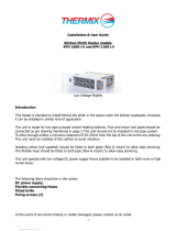
Low Voltage Hydronic Heating Performance Data
Heat outputs tested in accordance with BS 4856 Part 1.
Temperature Difference (°C)
Fan
Speed
Model
40° 45° 50° 55° 60° 40° 45° 50° 55° 60°
500 Duo
Normal 636 734 835 938 1043 2169 2505 2849 3201 3560
Boost 835 958 1083 1210 1340 2849 3268 3696 4130 4571
Heat Output (watts) Heat Output (Btu/h)
Duo (Hydronic/Electric) Heating Performance Data - Hydronic Mode
Temperature Difference (°C)
Fan
Speed
KICKSPACE
®
Performance Data (continued)
Available Finishes: White, Chrome, Brass, Brushed Stainless.
All remote wall switches are supplied with 3 metres of cable.
All models are equipped to facilitate direct wiring.
Suitable for uses with standard single gang surface or recessed
mounting box (not supplied). The switch must only be used to
operate a single KICKSPACE
®
unit.
For use on Hydronic and Hydronic-Electric (Duo) models only.
Not suitable for Electric only models.
N.B: When a remote wall switch is fitted, the fan speed control switch
on the KICKSPACE
®
facia grille becomes inoperable and must be
disconnected.
Model
Motor
Power (W)
Water
Content (l)
Unit Weight
(kg)
Air Flow
Model
Normal NormalBoost Boost
Noise Levels
Weight, Water Content and Motor Power
Model
500 25.7 38.1
600 26.4 37.2
800 28.5 49.8
Floor 27.4 56.1
600-12V 29.4 39.0
500 Duo 25.7 38.1
Sound Pressures at 2.5m (dBA)
Normal Boost
Air Flow (m
3
/h) Air Flow (ft
3
/h)
KICKSPACE
®
Remote Wall Switch (optional)
KICKSPACE
®
Technical Information
19
500 25 0.26 4.3
600 40 0.30 5.0
800 40 0.34 5.5
Floor 28 0.15 5.5
600-12V 40 0.30 7.9
*
500 Duo 25 0.26 4.5
500 70 90 2471 3177
600 106 138 3742 4872
800 139 210 4908 7415
Floor 76 169 2684 5968
600-12V 106 138 3742 4872
500 Duo 70 90 2471 3117
Air Flow
Model
Low LowHigh High
Air Flow (m
3
/h) Air Flow (ft
3
/h)
500E 70 90 2471 3177
600E 210 N/A 7560 N/A
Electric Heating Performance Data
Model
Low HighMedium
Heat Output (watts)
500E 1000 N/A 2000
600E 1000 2000 3000
* Includes transformer
Noise Levels
Noise levels tested in accordance with EN 23741.
Model
Sound Pressures at 2.5m (dBA)
500E 27.2 40.2
600E 38.0 N/A
Low High
Weight
Model
Unit Weight
(kg)
500E 3.0
600E 3.5
Noise levels tested
in accordance with
EN 23741.
Electric Models
The remote room thermostat is supplied white as standard and is
suitable for 500, 600 & 800 Hydronic models.
KICKSPACE
®
Remote Thermostat
KICKSPACE
®
models 500, 600, 800, 600-12V, 500 Duo and 500E
are supplied with a White (RAL 9003) grille. All these models are
also available in Brown (RAL 8017), Black (RAL 9011), Chrome,
Brushed Stainless Steel and Aluminium. The 600E facia grille is
an integral part of the product and can not be removed and is
supplied with either a White or Brown grille. The floor unit
model is only available with a Beige grille.
KICKSPACE
®
Grille Colour Options
KICKSPACE
®
Electrical Data
All KICKSPACE
®
models require an electrical supply of
220-240V-50Hz. All models can be used in conjunction with a
room thermostat, however it is essential that the thermostat used
is capable of carrying the electrical load.
Hydronic (KICKSPACE
®
500, 600 & 800)
Supplied with 2 metres of cable (0.75mm²).
Requires a supply fused at 3A.
Low Voltage Hydronic (KICKSPACE
®
600-12V)
Supplied with 2 metres of cable (0.75mm²).
Requires a supply fused at 3A.
N.B: Low voltage models comply with BS 7671 section 601 (IEE Safety
Extra Low Voltage wiring regulations for bathrooms). The transformer
complies with BS 3535. Where a remote switch or thermostat is used, the
line voltage to both is 12 volts maximum.
Hydronic Electric (KICKSPACE
®
500 Duo)
Supplied with 2 metres of cable (0.75mm²).
Requires a supply fused at 5A.
Electric (KICKSPACE
®
500E & 600E)
500E supplied with 2 metres of cable (1.0mm²).
Requires a supply fused at 10A.
600E supplied with 2½ metres of cable (1.0mm²).
Requires a supply fused at 13A.
KICKSPACE
®
Dimensions
KICKSPACE
®
800KICKSPACE
®
600KICKSPACE
®
500
KICKSPACE
®
500 Duo KICKSPACE
®
600-12V
N.B: Add 4.5mm to the chassis height of the above models to allow for rubber mountings and screws.
496
101
309
82
36
129
322
25
54
67
93
12
24
View on arrow
Cable Entries
Top view
Mains Cable
Cable Entry
FRONT GRILLE
159.5
496
101
318
28
56
15
15
54
70
93
321
142
177
FRONT GRILLE
Cable Entry
Mains Cable
Top view
Cable entries
View on arrow
550
101
54
93
67
12
24
View on arrow
Cable Entries
FRONT GRILLE
25
129
36
82
309
376
Mains Cable
Top view
Cable Entry
550
101
54
93
67
12
24
View on arrow
Cable Entries
FRONT GRILLE
25
129
36
82
309
376
Mains Cable
Top view
Cable Entry
101
603
FRONT GRILLE
Top view
54
93
67
12
24
View on arrow
Cable Entries
25
129
36
82
309
447
Mains Cable
Cable Entry
20
KICKSPACE
®
Technical Information
KICKSPACE
®
Dimensions (continued)
KICKSPACE
®
Kickboard Dimensions
Dimensions of opening to be cut in Kickboard -
KICKSPACE
®
500, 600, 600-12V, 800, 500 Duo,
500E, 600E
Option A (Excluding 500E)
Option B (Excluding 600E)
Model
ABC
500, 500 Duo, 500E 466 99 17
600, 600-12V 520 99 17
800 573 99 17
600E 540 95 N/A
KICKSPACE
®
Floor
Connections
Dimensional View
KICKSPACE
®
600EKICKSPACE
®
500E
496
101
321
203
177
FRONT GRILLE
Mains Cable
Top view
Cable entries
View on arrow
93
88
225
120
360
120
600
100
175
Cable entry
View on arrow
105
70
14
38
38
240
362
402
248
Cable entry
Flow and Return
connections
244
422
240
362
210
Flange depth
Flange width
N.B: All connections accessible
from the top of unit.
KICKSPACE
®
Technical Information
21
Dimensions (mm)
N.B: KICKSPACE
®
500E: Add 4.5mm
to the chassis height of the above
models to allow for rubber mountings
and screws.
  • Page 1 1
  • Page 2 2
  • Page 3 3
  • Page 4 4
  • Page 5 5
  • Page 6 6
  • Page 7 7
  • Page 8 8
  • Page 9 9
  • Page 10 10

Ask a question and I''ll find the answer in the document

Finding information in a document is now easier with AI