Page is loading ...

INSTRUCTION
MANUAL
• This is not a toy! Not suitable for children under 14 years old without adult supervision.
• Ceci n’est pas un jouet. Ne convient pas aux enfants de moins de 14 ans sans la surveillance d’un adulte.
• Kein Spielzeug. Nichte geeignet für Kinder unter 14 Jahren ohne Aufsicht Erwachsener.
• No es un juguete. No recomendado para niños menores de 14 años.
ENGLISHFRAN
Ç
AISDEUTSCHESPAÑ OL

2
Knife
Cutter
CHASSIS
Curved lexan scissors
Ciseaux a lexan courbes
EX 421200
HT 421900
Hex wrench complety set
(1,5-2-2,5-3mm)
Coret de tournevis allen
EX 421939
Wheel nuts wrench 17mm
Clé à roue 17mm
EX 421984
Aluminium Multi-tool for Shocks
Outil multifonction pour amortisseur
Multifonction pliers complety set
Gamme multifonction de pinces
Turnbuckle wrench
Clé de réglage biellette
EX-421942
EX-421943
EX-421945
4.0MM
5.0MM
6.0MM
Li-Po safety bag
Housse de charge LiPo
XT-LIPOBAG
TOOLS REQUIRED NOT INCLUDED IN THE KIT / OUTILLAGE REQUIS NON INCLUS DANS LE KIT
4xAA Alkaline batteries
4 piles Alkaline R6
NOT PROVIDED WITH THE CAR / NON FOURNIS AVEC LE VÉHICULE
ENGLISHfraN
ç
a ISDEUTSCH
3
WARRANTY AND SERVICE INFORMATIONS
COMPONENT WARRANTY PERIOD
PlEASE READ ThE FOllOWINg INFORMATION CAREFullY !
Please note this is a high-quality hobby product and not a toy. Therefore, it is necessary that children under 14 years are
supervised by an adult. The guardians and / or parents have the responsibility to provide the appropriate guidance and
supervision of the minors .
This product has a 90 day warranty, which is only guaranteed to the original purchaser. The warranty valid only to products
that have been purchased from an authorized Hobbytech dealer. Warranty claims will be processed only with a valid proof of
purchase / receipts. If within the warranty period, a portion of the product fails due to manufacturing defects, then it is within
the discretion of Hobbytech to repair it or replace it. The decision to repair or replace the part will be taken by Hobbytech. After
use, we do not oer new for old warranty.
WARRANTY DISCLAIMER
This high performance model was made with highest attention and care and should be treated with respect. Excluded from
the warranty are components that have been damaged by wrong installation, mishandling, accident, operation, maintenance,
lack of maintenance and care, as well as abuse and / or repair attempts. Furthermore excluded from the guarantee are wearing
parts such as fuses and batteries, visual impairments, shipping -, transport costs.
WARRANTY CLAIM
Please contact your dealer with the warranty claim and / or repair. Your dealer and Hobbytech will make an proper decision
that will help you as soon as possible. For invalid warranty claims you may be charged for the processing costs before the parts
are returned. All repairs which are necessary by negligence or abuse are bill in advance. In case you decide that you not want
to repair your product then Hobbytech editing and reserves the right to charge shipping costs .
Declaration of conformity in accorDance with the raDio &
telecommunications terminal equipment (r&tte) Directive 1999/5ec.
Sarl Imodel
5 place de Rome
13006 Marseille
France
Declares that he following product :
REVOLT BX10 3.0 RTR
w/ WAVE XT200/XR200 (KTH-90900-02G)
Item Number: XT WAVE-SET-WP
Equipment class: 1
Complies with the essential requirements and other relevant provisions
of the FTEG (Article 3 of the R&TTE directive)
• Protection of health and safety of the user and any other person,
(article 3.1a of the Directive)
Standards applied: EN 62311:2008
• The essential requirements of the Electromagnetic Compatibility
Directive (article 3.1b)
Standards applied: EN 301 489-1 V1.9.2 (2011-09)
EN 301 489-3 V1.4.1 (2002-08)
• Eective use of the radio spectrum/orbital resource so as to avoid
harmful interference (article 3.2).
Standards applied: EN 300 440-1 V1.6.1 (2010-08)
EN 300 440-1 V1.4.1 (2010-08)
Manufacturer Adress: Sarl Imodel
5 place de Rome
13006 Marseille
France
Date of issue: September 27, 2012
This product must not be disposed of with other
waste. Instead, it is the user’s responsibility to
dispose of their waste equipment by handing
it over to a designated collection point for the
recycling of waste electrical and electronic
equipment. The separate collection and
recycling of your waste equipment at the time of
disposal will help to conserve natural ressources
and ensure that it is recycled in a manner that
protects human health and the environment.
Help us to protect the environment and respect
our ressources !
i.A.
Notice 1/10ème-Multilingue.indd 3 08/11/13 15:19
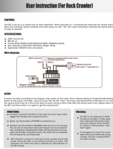
Battery
holder
Receiver
Box
Steering
servo
ESC
Motor
Rear tyre
Front tyre
Front
shock unit
Front Bumper
Rear
shock unit

ENGLISHfraN
ç
aISDEUTSCHESpaÑ oL
3
ENGLISHfraN
ç
a ISDEUTSCH
3
WARRANTY AND SERVICE INFORMATIONS
COMPONENT WARRANTY PERIOD
PlEASE READ ThE FOllOWINg INFORMATION CAREFullY !
Please note this is a high-quality hobby product and not a toy. Therefore, it is necessary that children under 14 years are
supervised by an adult. The guardians and / or parents have the responsibility to provide the appropriate guidance and
supervision of the minors .
This product has a 90 day warranty, which is only guaranteed to the original purchaser. The warranty valid only to products
that have been purchased from an authorized Hobbytech dealer. Warranty claims will be processed only with a valid proof of
purchase / receipts. If within the warranty period, a portion of the product fails due to manufacturing defects, then it is within
the discretion of Hobbytech to repair it or replace it. The decision to repair or replace the part will be taken by Hobbytech. After
use, we do not oer new for old warranty.
WARRANTY DISCLAIMER
This high performance model was made with highest attention and care and should be treated with respect. Excluded from
the warranty are components that have been damaged by wrong installation, mishandling, accident, operation, maintenance,
lack of maintenance and care, as well as abuse and / or repair attempts. Furthermore excluded from the guarantee are wearing
parts such as fuses and batteries, visual impairments, shipping -, transport costs.
WARRANTY CLAIM
Please contact your dealer with the warranty claim and / or repair. Your dealer and Hobbytech will make an proper decision
that will help you as soon as possible. For invalid warranty claims you may be charged for the processing costs before the parts
are returned. All repairs which are necessary by negligence or abuse are bill in advance. In case you decide that you not want
to repair your product then Hobbytech editing and reserves the right to charge shipping costs .
Declaration of conformity in accorDance with the raDio &
telecommunications terminal equipment (r&tte) Directive 1999/5ec.
Sarl Imodel
5 place de Rome
13006 Marseille
France
Declares that he following product :
REVOLT BX10 3.0 RTR
w/ WAVE XT200/XR200 (KTH-90900-02G)
Item Number: XT WAVE-SET-WP
Equipment class: 1
Complies with the essential requirements and other relevant provisions
of the FTEG (Article 3 of the R&TTE directive)
• Protection of health and safety of the user and any other person,
(article 3.1a of the Directive)
Standards applied: EN 62311:2008
• The essential requirements of the Electromagnetic Compatibility
Directive (article 3.1b)
Standards applied: EN 301 489-1 V1.9.2 (2011-09)
EN 301 489-3 V1.4.1 (2002-08)
• Eective use of the radio spectrum/orbital resource so as to avoid
harmful interference (article 3.2).
Standards applied: EN 300 440-1 V1.6.1 (2010-08)
EN 300 440-1 V1.4.1 (2010-08)
Manufacturer Adress: Sarl Imodel
5 place de Rome
13006 Marseille
France
Date of issue: September 27, 2012
This product must not be disposed of with other
waste. Instead, it is the user’s responsibility to
dispose of their waste equipment by handing
it over to a designated collection point for the
recycling of waste electrical and electronic
equipment. The separate collection and
recycling of your waste equipment at the time of
disposal will help to conserve natural ressources
and ensure that it is recycled in a manner that
protects human health and the environment.
Help us to protect the environment and respect
our ressources !
i.A.
Notice 1/10ème-Multilingue.indd 3 08/11/13 15:19
KONECT KT2S TRANSMITTER
FCC ID: YDTHBT1000 FCC Statement: This equipment has been tested and found to comply with the limits for Part 15 of the FCC rules. These limits are designed to provide reasonable
protection against harmful interference in a residential installation.
This equipment generates, uses and can radiate radio frequency energy and, if not installed and used in accordance with the instructions, may cause harmful interference to radio
communications.
However, there is no guarantee that interference will not occur in a particular installation. If this equipment does cause harmful interference to radio or television reception, which can be
determined by turning the equipment o and on, the user is encouraged to try to correct the interference by one or more of the following measures:
• Reorient or relocate the receiving antenna. • Increase the separation between the equipment and receiver.
• Connect the equipment to an outlet on a circuit dierent from that to which the receiver is connected.
This device complies with Part 15 of the FCC Rules. Operation is subject to the following two conditions:
(1) this device may not cause harmful interference,
(2) this device must accept any interference received, including interference that may cause undesired operation.
Notice: Modifications to this product will avoid the user’s authority to operate this equipment.
WARRANTY AND SERVICE INFORMATIONS
COMPONENT WARRANTY PERIOD
PLEASE READ THE FOLLOWING INFORMATION CAREFULLY !
Please note this is a high-quality hobby product and not a toy. Therefore, it is necessary that children under 14 years are
supervised by an adult. The guardians and / or parents have the responsibility to provide the appropriate guidance and
supervision of the minors .
This product has a 90 day warranty, which is only guaranteed to the original purchaser. The warranty valid only to products
that have been purchased from an authorized Hobbytech dealer. Warranty claims will be processed only with a valid proof of
purchase / receipts. If within the warranty period, a portion of the product fails due to manufacturing defects, then it is within
the discretion of Hobbytech to repair it or replace it. The decision to repair or replace the part will be taken by Hobbytech. After
use, we do not oer new for old warranty.
WARRANTY DISCLAIMER
This high performance model was made with highest attention and care and should be treated with respect. Excluded from
the warranty are components that have been damaged by wrong installation, mishandling, accident, operation, maintenance,
lack of maintenance and care, as well as abuse and / or repair attempts. Furthermore excluded from the guarantee are wearing
parts such as fuses and batteries, visual impairments, shipping -, transport costs.
WARRANTY CLAIM
Please contact your dealer with the warranty claim and / or repair. Your dealer and Hobbytech will make an proper decision
that will help you as soon as possible. For invalid warranty claims you may be charged for the processing costs before the parts
are returned. All repairs which are necessary by negligence or abuse are bill in advance. In case you decide that you not want
to repair your product then Hobbytech editing and reserves the right to charge shipping costs .
DECLARATION OF CONFORMITY IN ACCORDANCE WITH THE RADIO &
TELECOMMUNICATIONS TERMINAL EQUIPMENT (R&TTE) DIRECTIVE 1999/5EC.
Sarl Imodel
5 place de Rome
13006 Marseille
France
Declares that he following product :
• NXT EP (# 1.SPIRIT.NXT.EP)
• w/ KONECT KT2S Transmitter & Receiver
Item Number: KN-KT2S/SET
Equipment class: 1
Complies with the essential requirements and other relevant provisions of the FTEG (Article
3 of the R&TTE directive)
• Protection of health and safety of the user and
any other person, (article 3.1a of the Directive)
Standards applied: EN 62311:2008
• The essential requirements of the
Electromagnetic Compatibility Directive (article 3.1b)
Standards applied: EN 301 489-1 V1.9.2 (2011-09)
EN 301 489-3 V1.4.1 (2002-08)
• Eective use of the radio spectrum/orbital
resource so as to avoid harmful interference (article 3.2).
Standards applied: EN 300 440-1 V1.6.1 (2010-08)
EN 300 440-1 V1.4.1 (2010-08)
Manufacturer Address: Sarl Imodel
5 place de Rome
13006 Marseille
France
Date of issue: September 27, 2012
This product must not be disposed of with other
waste. Instead, it is the user’s responsibility to
dispose of their waste equipment by handing
it over to a designated collection point for the
recycling of waste electrical and electronic
equipment. The separate collection and
recycling of your waste equipment at the time of
disposal will help to conserve natural ressources
and ensure that it is recycled in a manner that
protects human health and the environment.
Help us to protect the environment and respect
our ressources !
i.A.

ENGLISHfraN
ç
aISDEUTSCHESpaÑ oL
4
IMPORTANT READ THIS BEFORE RUNNING
PLEASE READ ALL INSTRUCTIONS AND FAMILIARIZE YOURSELF WITH THE PRODUCTS AND CONTROL BEFORE
OPERATION.
This product is not a toy. It is a high performance model product. It is important to familiarize yourself with the model, its
manual, and its construction before assembly and operation. Adult supervision is necessary
CAUTION
To avoid serious personal injury and property damage, operate all remotely controlled models in a responsive manner as out-
lined below.
R/C car models can exceed speeds of 40km/h (25mph), and cannot be stopped quickly.
❶ Never run R/C models on the street or highways, as it could cause or contribute to serious trac accidents.
❷ Never run an R/C model near people or animals, nor use people or animals as obstacles when operation R/C vehicles.
❸ To avoid injury to persons or animals, and damage to property, never run a R/C model in a confined or crowed area.
❹ Running R/C models into furniture or other inanimate objects will cause damage to the objects and the R/C models.
CAUTION DURING OPERATIONS
When the R/C model is in operation, dot not touch any of its moving parts, such as drive shafts, wheels, as the rotating parts
can cause serious injury.
❶ The vehicle motor gets very hot during running and could cause burns if touched.
❷ Make sure that no one else is using the same frequency as yours in your running area. Using the same frequency at the same
time, whether is driving, flying or sailing, can cause loss of control of the R/C models, resulting in serious accidents.
❸ Properly connect plugs. To prevent electrical shock and/or damage to the product resulting from a short-circuit; insulate
connections with heat shrink tubing or electrical tape. Before running vehicle, check that battery wiring and plugs are not so
loose as to drag on the ground. Properly secure cables using electrical tape or nylon tie-wraps.
❹ Sti rotation of gears, shafts, joints and wheels can burn out the motor. It’s recommended to check proper joint and shaft
rotation by using one 1,5V dry cell during assembly of the model.
A worn motor will overheat and result in a short running time. Replace a worn out motor as soon as possible.
❺ R/C models will run out of control when either the receiver or transmitter battery voltage drops o. Stop the vehicle
immediately when the car starts to show down to prevent it from running out of control.
SAFETY PRECAUTIONS
Follow the outlined rules for safe radio control operation.
Avoid running the car in crowed area and near small children.
Make sure that no one else is using the same frequency in your running area. Using the same frequency at the same time can
cause serious accidents, whether it’s driving, flying or sailing.
Avoid running in standing water and rain. If R/C unit, motor, or battery get wet, clean and dry throughly in a dry shaded area.
R/C operating procedures
❶ Make sure the transmitter controls and trims are in neutral. Switch on transmitter.
❷ Switch on receiver.
❸ Inspect operation using transmitter before running.
❹ Adjust steering servo and trim so that the model runs straight with transmitter in neutral.
❺ Reverse sequence to shut down after running.
❻ Make sure to disconnect/remove all batteries.
❼ Completely remove sand, mud, dirt etc
❽ Store the car and batteries separately when not in use
SETTING UP THE MODEL
To greatly enhance the overall performance of your car, it’s necessary to tune the vehicle to the track (and its surface
conditions) on which you will be racing. Make adjustments referring to the instruction manual, keeping in mind that “balance” is
the key word.
❶ Tires
Tires have a great influence on the performance of your car, and are normally the first components tuned. Select the right tires
for the track you are racing on.
❷ Toe-in and Toe-out
Adjusting the car toe-in a little, by pointing the wheel inwards, provides the car with good straight running and moderate
steering characteristics. Toe-out, which point the wheels outwards, gives sharp and crisp steering. Take care not to overdo.
❸ Camber angle
While taking the corners, the car is forced to go outwards, causing instability. The area of contact on each tire is determined
by the camber angle, and therefore the traction of the tires can be made greater or lesser by adjustment of camber angle. To
increase traction during cornering, adjust camber angle negative, and reduce traction, adjust for positive camber.
❹ Ground clearance and suspension drop
Ground clearance and/or rebound stroke has a great eect on stability during cornering, acceleration, and braking. Ground
clearance can be adjusted by altering damper spring tension and stiness.
❺ Gear ratio
Proper gear ratio should be determined by the available output power of the motor; type of battery; track condition and layout
It should be also noted that running the car on a good grip surface suggests use of pinion gear 1 teeth smaller, in order to
eectively use all of the available battery power.

ENGLISHfraN
ç
aISDEUTSCHESpaÑ oL
5
4S Soft Case
2 x 3S Hard Case
4S Hard Case 2 x 2S Hardcase
THIS PLATFORM IS LIPO 2X2S OR 3S OR 4S LIPO CAPABLE
• To be able to use the diferent lipo battery packs configuration you may have to use the extra battery straps provided with this car.
• If you want to use 4S HARDCASE Lipo battery you will have to disasemble the upper battery tray and put the straps like
• You can aslo use provided battery foam to change the weight balance of your car (move the battery to the front or to the rear)
Hobbytech SPIRIT NXT EP
Buggy (46 T Spur)
Motor Kv
Motor Gear (T)
LiPo 3S LiPo 4S LiPo 6S
1400 21 14
1600 18 12
1800 22 16 11
2000 20 15 10
2200 18 14
2400 16 13
2600 15 12
Note: Use a appropriate motor gear for
your motor. A bad compromise between the
motor gear and the spur gear can damage
your electrical components
Hobbytech SPIRIT NXT EP Buggy ratio chart
Motor Gear (T)
13 14 15 16 17 18 19
Spur
44
11,20 10,40 9,71 9,10 8,57 8,09 7,61
46
11,70 10,87 10,14 9,51 8,45 8,45 8,01
Use Thread Lock
WARNING: If you change the battery configuration you will have to change your
motor gear to prevent any technical problem please check bellow gear ratio chart!

ENGLISHfraN
ç
aISDEUTSCHESpaÑ oL
6
EVEN IF THIS CAR IS A READY TO RUN KIT, YOU STILL HAVE SOME LITTLE THINGS TO DO TO FAMILIARI ZE WITH YOUR
PRODUCT.
PLEASE FOLLOW THESE STEPS.
Steering Wheel : Control direction (Left / Right) of the
RC model
Throttle Trigger : Control speed and direction (Forward/
Brake/Backward) of the driving model.
Antenna : Transmit signal to the model
Power ON / OFF : Power ON / OFF the transmitter
SYNC & Battery Indicator : Top Green LED light indicates
synchronization status and/or
adequate battery power supply.
Power Indicator : LED light indicates power “ON”.
ATV : Adjustable Steering Rate by ATV dial
ST. Trim Dial : Adjust the neutral position of steering
servo when model wheels are straight
ahead.
TH. Trim Dial : Make sure the model stays still when
releasing the throttle trigger.
Battery Compartment Tray : Cover and hold the batteries powering
the transmitter.
KT2S TRANSMITTER FUNCTIONS
PRERUN CHECK
Battery
Compartment Tray
Steering
Trim Dial
Steering
Wheel
Throttle
Trigger
Throttle
Trim Dial
Bind /
Setup Key
Antenna
Power
Indicator
A
TV
Power
ON / OFF
Throttle
Reverse Switch
Steering
Reverse Switch
RECEIVER AND SERVO CONNECTION
ESC
Receiver
CH1
Steering Servo
Power Switch
Connect to
battery
Connect to motor
* Always turn on the transmitter first by sliding the switch on
the left side from bottom to top. The green lights above the
switch should light up. If not, you need to check for low or
incorrectly installed batteries.
1. Steering : Adjust the steering
trim to keep the front wheels
in straight line when steering
wheel remains in NEUTRAL
position.
2. Throttle : Adjust the throttle
trim to ensure the wheels stop
rotating when throttle trigger
remains in NEUTRAL position.
LED
indicator
LED
indicateur
BATTERY INSTALLATION
Supplied with 4 x 1.5V AA Batteries,
KT2S can be operated a few hours.
Installation: ❶ Remove the battery
compartment cover as shown
below.
❷ Install the batteries
observing the polarity
marked on battery
compartment.
❸ Then reinstall the battery
compartment cover as the
Picture shown below.
CAUTION :
Do not dispose of batteries in fire,
short their terminals, apply heat to
them or disassemble them. .
Used batteries: Please dispose of
used batteries properly, following
any local regulations.
Battery distributors are required by
law to take back spent batteries;
they must not be thrown away as
household waste.
CH2

ENGLISHfraN
ç
aISDEUTSCHESpaÑ oL
7
Place model on a block to prevent wheels from touching the
ground.
A
Connect battery to ESC. Fix the wire correctly with the
provided connectors.
You must check the signal of transmitter and receiver before
you operating it at first.
Make sure TH Trim is on neutral
TURN OFF THE TRANSMITTER AND RECEIVER
B
Press and Hold the BIND button on the receiver while
turning on the receiver
C
.
Release the BIND button when the LED flashes green.
While the green LED flashes, press the BIND button to select
the frame rate.
- Faster flashes= high frame rate (7ms), for digital servo
- Slower flashes= low frame rate (15ms), for analog servo
D
Press and Hold the BIND key of the Transmitter (1),
and then turn on the Transmitter (2), the Transmitter will
communicate with the receiver.
When the receiver LED is solid on, the pairing process is done,
and the receiver is paired with the transmitter.
BIND
A
C
B
D
(1)
(2)
BATTERY LED INDICATOR
- During normal operation, the LED should be solid green ON
- When battery voltage is dropped below 3.8V, the LED will become red color and flashing very slowly, to indicate battery is
low, you should replace new battery as soon as possible.
HOW TO CONTROL YOUR MODEL 1
NEUTRAL POSITION
1. Pull up the trigger in order to brake or speed down 2. Pull the trigger in order to go forward or speed up
BRAKE / SPEED
DOWN POSITION
FORWARD / SPEED
UP POSITION

ENGLISHfraN
ç
aISDEUTSCHESpaÑ oL
8
ABOUT THE RADIO SYSTEM
Reversing is used to change the response direction of steering
wheel and throttle trigger.
KT2S Transmitter features 2 reversing functions: Steering
Reverse and Throttle Reverse.
Steering Reverse: Reverse the response direction when
operating steering wheel. Turning left steering wheel, the
model turns right while turning right the model turns left.
Throttle Reverse: Reverse the response direction when operating
throttle trigger. Pushing forward throttle trigger the model moves
backward while pulling back, the model moves forward.
Adjustable Steering Rate enables to adjust the same maximum steering angle of servo on both sides (Left and Right) when
model makes steering. The Adjustable Steering Rate aects the sensitivity of servo. Reducing dual rate value can lower the
sensitivity of servo and reduce the same maximum steering angle on both sides. Remember to adjust the dual rate value within
the adjustment range.
KT2S features two trimming functions:
Steering Trim and Throttle Trim.
Steering Trim Dial:
Adjust the neutral position of steering servo when the wheels
are straight ahead. Normally steering trim is adjusted until the
model can keep straight tracks.
Throttle Trim Dial:
Adjust neutral position of throttle servo. Make sure the model
stays still when releasing the throttle trigger.
Reversing
Adjustable Steering Rate (ATV)
Trimming
PROGRAMMING THE ENDPOINTS
Steering End-points programming
1) Steering End-points programming
• To set the Right End point of Steering:
- During normal operation, hold the Steering wheel at right-
most, and then hold the BIND key over 1 sec
- LED will become solid red color, and the Right End-point
will be reset to max value
- Next, use the steering wheel to let the steering servo point
at the expected right most location. Now, pressing the BIND
key to save this Right End Point: the LED will be flashed 4
times while data is saved.
• To set the Left End point of Steering:
- Similar to above, logically hold the Steering at Left-most
position and hold the BIND key over 1 sec.
Throttle End-points programming
• To set the Forward End point:
Similarly, hold the Throttle at Forward-most position to set
Forward End Point, hold the BIND key over 1 sec to enter
Forward End Point programming...
• To set the Reverse End point:
Similarly, hold the Throttle at Reverse-most position to set
Reverse End Point, hold the BIND key over 1 sec to enter
Reverse End Point programming...
HOW TO CONTROL YOUR MODEL 2
If the wheels operate in the opposite direction, operate the servo reverse switch (ST in position NOR).
NEUTRAL
LEFT RIGHT

ENGLISHfraN
ç
aISDEUTSCHESpaÑ oL
9
High power system for RC model can be very dangerous, so we strongly suggest you read this manual carefully. In that
KONECT have no control over the correct use, installation, application, or maintenance of our products, no liability shall be
assumed nor accepted for any damages, losses or costs resulting from the use of the product.
ANY CLAIMS ARISING FROM THE OPERATING, FAILURE OF MALFUNCTIONING ETC. WILL BE DENIED. WE ASSUME NO LIABILITY FOR
PERSONAL INJURY, CONSEQUENTIAL DAMAGES RESULTING FROM OUR PRODUCT OR OUR WORKMANSHIP. AS FAR AS IS LEGALLY
PERMITTED, THE OBLIGATION TO COMPENSATION IS LIMITED TO THE INVOICE AMOUNT OF THE AFFECTED PRODUCT.
FEATURES
1. Specially designed for buggy, truggy and truck, with excellent start-up, acceleration and linearity features.
2. Compatible with sensorless brushless motor.
3. 3 running modes suitable for dierent applications (“Racing” mode, “General” and “Rock crawler”).
4. Proportional ABS brake function with 5 steps of maximum brake force adjustment, 8 steps of drag-brake force adjustment.
5. 9 start modes (“Punch”) from “Soft” to “Very aggressive” to be suitable for dierent chassis, tires and tracks.
6. Multiple protection features: Low voltage cut-o protection for lithium or nickel battery / Over-heat protection / Throttle
signal loss protection / Motor blocked protection.
7. User programmable. Two program methods are supported: The “SET” button on the ESC, the digital LED program card.
The program card is pocket-sized and has friendly user interface to be easily used.
8. Waterproof and Dustproof.
(Please remove the cooling fan when running car in water, and after running, please make the ESC clean and then dry it to
avoid the oxidation of copper connectors).
SPECIFICATIONS
Model KONECT 150AMP WP “by HOBBYWING”
Cont. / Burst Current 150A / 950A
Resistance 0.0035 ohm
Suitable Car 1/8 scale SCT / Buggy / Truggy - On-road car
Motor Turns
4S LiPo : Kv ≤ 3000
6S LiPo : Kv ≤ 2400
Battery
9-18 cells NiMH
3-6S Li-Po
BEC Output 6V/3A (switch mode)
Motor Type Sensorless brushless motor
Dimension & weight 59,5 x 48 x 42 & 178g
BEGIN TO USE THE NEW ESC
WARNING! THIS BRUSHLESS SYSTEM IS VERY POWERFUL! FOR
SAFETY, PLEASE ALWAYS KEEP THE WHEELS AWAY FROM THE
TRACK WHEN YOU BEGIN TO SWITCH ON THE ESC.
1. Connect the ESC, motor, receiver, battery and servo
according to the following diagram
The #A, #B, #C wires of the ESC can be connected with the
motor wires freely (without any order). If the motor runs in the
opposite direction, please swap any two wire connections.
2. Throttle Range Setting (Throttle Range Calibration)
In order to make the ESC fit the throttle range, you must
calibrate it when you begin to use a new ESC, or a new
transmitter, or change the settings of neutral position of the
throttle stick, ATV or EPA parameters, etc. Otherwise the ESC
cannot work properly.
There are 3 points need to be set, they are the top point of
“forward”,” backward” and the neutral point.
The following pictures show how to set the throttle range with
a Futaba
TM
transmitter.
A) Switch o the ESC, turn on the transmitter”, set the
“EPA/ATV” value of throttle channel to “100%”, and
disable the ABS function of your transmitter.
B) Hold the “SET” key and then switch on the ESC, and
release the “SET” key as soon as possible when the red
LED begins to flash. (Note2)
150
amp
BRUSHLESS WATERPROOF ESC INSTRUCTION MANUAL
Note1: the cooling fan of ESC is supplied by the built-in BEC,
so it is always working under 6V

ENGLISHfraN
ç
aISDEUTSCHESpaÑ oL
10
Note2: If you don’t release the “SET” key after the red LED begins to flash, the ESC will enter the program mode, in such a case,
please switch o the ESC and re-calibrate the throttle range again from step A to step D.
C) Set the 3 points according to the steps shown as the
pictures on the right side.
1) The neutral point
Move the throttle stick at the neutral point, and then
click the SET key, the green LED flashes 1 time.
2) The end point of forward direction
Move the throttle stick at the end point of forward
direction, and then click the SET key, the green LED
flashes 2 times.
3) The end point of backward direction
Move the throttle stick at the end point of backward
direction, and then click the SET key, the green LED
flashes 3 times.
D) Throttle range is calibrated; motor can be started after
3 seconds.
3. Check the LED Status in Normal Running
1) Normally, if the throttle stick is in the neutral range, neither the red LED nor the green LED lights.
2) The red LED lights when the car is running forward or backward and it will flash quickly when the car is braking
3) The green LED lights when the throttle stick is moved to the top point (end point) of the forward zone.
PROTECTION FUNCTION
1. Low voltage cut-o protection: if the voltage of a LiPo battery pack is lower than the threshold for 2 seconds, the ESC will cut
o the output power. Please note that the ESC cannot be restarted if the voltage of each LiPo cell is lower than 3,5V.
2. Over-heat protection: when the temperature of the ESC is over a factory preset threshold for 5 seconds, the ESC will cut o
the output power. You can disable the over-heat protection function for competition race.
3. Throttle signal loss protection: the ESC will cut o the output power if the throttle signal is lost for 0.2 second.
TROUBLE SHOOTING
TROUBLE POSSIBLE REASON SOLUTION
After power on, motor doesn’t work,
and the cooling fan doesn’t work
The connections between battery pack and
ESC are not correct
Check the power connections
After power on, motor can’t work, but
emits “beep-beep-, beep-beep-” alert
tone. (Every “beep-beep-” has a time
interval of 1 second )
Input voltage is abnormal, too high or too
low
Check the voltage of the battery pack
After power on, red LED always lights, the
motor doesn’t work
Throttle signal is abnormal
Plug the control wire into the throttle channel of the
receiver correctly.
The motor runs in the opposite direction
when it is accelerated
1) The wire connections between ESC and
the motor are not correct
2) The chassis is dierent from the popular
design
Method #1: Swap any two wire connections between the
ESC and the motor
Method #2: Change the “Motor Rotation” programmable
item to “CW(Clockwise)”
The motor suddenly stops running while in
working state
The throttle signal is lost
Check the transmitter and the receiver
Check the signal wire from the throttle channel of your
receiver
The ESC has entered the Low Voltage
Protection Mode or Over-heat Protection
Mode
Red LED flashes means Low Voltage Green LED flashes
means Over-heat
Random stop or restart irregular working
state
1) Some connections are not reliable
2) Wrong charge of the battery pack
3) Gear ratio is too long
4) Start mode (punch) is too agressive
1) Check all the connections: battery pack connections,
throttle signal wire, and motor connections, etc.
2) Replace the battery pack
3) Change the gear ratio
4) Go down the Start Mode to a softer value
When the throttle stick is in the neutral
range, the red LED and the green LED
flashes synchronously
Over current protection, motor
demagnetization, or motor is over load
1) Reduce the load (use softer gear ratio or reduce the
input voltage)
2) Change the motor
Cannot connected with the LED Program
Card or LCD Program Box
Mistakenly uses the Rx wire to connect to
the program card/box
Connect the program card/box to the special
programming port of tthe ESC, don’t use the Rx wire

ENGLISHfraN
ç
aISDEUTSCHESpaÑ oL
11
PROGRAM THE ESC
1. Program Method
Note3: • In the program process, the motor will emit “Beep” tone at the same time when the LED is flashing.
• If the “N” is bigger than the number “5”, we use a long time flash and long “Beep---” tone to represent “5”, so it is
easy to identify the items of the big number.
For example, if the LED flashes as the following:
“A long time flash + a short time flash” (Motor sounds “Beep---Beep”) = the No. 6 item
“A long time flash + 2 short time flash” (Motor sounds “Beep---BeepBeep”) = the No. 7 item
“A long time flash + 3 short time flash” (Motor sounds “Beep---BeepBeepBeep”) = the No. 8 item …… And so on.
Programmable Items List
(Italic texts in the above form are the default settings)
1 2 3 4 5 6 7 8
1. Running Mode
Forward Only
with Brake
Forward/Reverse
with Brake
2. Drag Brake Force
3. Low Voltage
Cut-Off Threshold
Non-Protection 2.6V/Cell 2.8V/Cell
3.2V
/Cell
3.4V
/Cell
4. Start Mode (Punch) Level1 Level2 Level6 Level7 Level8 Level9
5. Max Brake Force 25%
9
Programmable
Items
Basic Items
Programmable Value
3.0V
/Cell
10% 20% 40% 60% 80% 100%
100% Disable
5%
Level4
Level3
75%
Level5
0%
50%

ENGLISHfraN
ç
aISDEUTSCHESpaÑ oL
12
2. Programmable Values
2.1. Running Mode: With “Forward Only with Brake” mode, the car can go forward and brake, but cannot go backward, this mode
is suitable for competition; “Forward/Reverse with Brake” mode provides backward function, which is suitable for daily training.
Note: “Forward/Reverse with Brake” mode uses “Double-click” method to make the car go backward. When you move the
throttle stick from forward zone to backward zone for the first time (The 1st “click”), the ESC begins to brake the motor, the motor
speeds down but it is still running, not completely stopped, so the backward action is NOT happened immediately. When the
throttle stick is moved to the backward zone again (The 2nd “click”), if the motor speed is slowed down to zero (i.e. stopped),
the backward action will happen. The “Double-Click” method can prevent mistakenly reversing action when the brake function
is frequently used in steering.
By the way, in the process of braking or reversing, if the throttle stick is moved to forward zone, the motor will run forward at once.
“Forward/Reverse” mode uses “Single-click” method to make the car go backward. When you move the throttle stick from forward
zone to backward zone, the car will go backward immediately. This mode is usually used for the Rock Crawler.
2.2. Drag Brake Force: Set the amount of drag brake applied at neutral throttle to simulate the slight braking eect of a neutral
brushed motor while coasting.
2.3. Low Voltage Cut-O: The function prevents the lithium battery pack from over discharging. The ESC detects the
battery’s voltage at any time, if the voltage is lower than the threshold for 2 seconds, the output power will be cut o, and the red
LED flashes in such a way: “❏-❏-, ❏-❏-, ❏-❏-”.
There are 6 preset options for this item. You can customize the cuto threshold by using a LCD program box (optional equipment)
to trim it with a step of 0.1V, so it will be more suitable for all kinds of batteries (NiMH, NiCd, Li-ion, Lipo, LFP,etc). Please always
keep in mind that the customized value is not for each cell, it is for the WHOLE battery pack.
2.4. Start Mode (Also called “Punch”): Select from “Level 1” to “Level 9” as your like, Level 1 has a very soft start eect, while level 4
has a very aggressive start eect. From Level 1 to Level 9, the start force is increasing.
Please note that if you choose “Level7” to “Level9” mode, you must use good quality battery pack with powerful discharge ability,
otherwise these modes cannot get the burst start eect as you want. If the motor cannot run smoothly (the motor is trembling),
it may caused by the weak discharge ability of the battery pack, please choose a better battery, choose low value for “punch” or
increase the gear rate.
2.5. Maximum Brake Force: The ESC provides proportional brake function. The brake force is related to the position of the
throttle stick. Maximum brake force refers to the force when the throttle stick is located at the top point of the backward zone.
A very large brake force can shorten the brake time, but it may damage the gears.
3. Reset All Items To Default Values
At any time when the throttle is located in neutral zone (except in the throttle calibration or parameters program process), hold
the “SET” key for over 3 seconds, the red LED and green LED will flash at the same time , which means each programmable item
has be reset to its default value.
OPTIONAL ACCESSORIES
2. LED Program Card
Program card is an optional equipment which needs to be purchased separately. It has
a friendly user interface. The process of programming the ESC becomes quite easy and
fast with this pocket sized device. When the programmable value needs to be changed,
please just plug the control wires of the ESC (trio wires with black, red and white color)
into the socket of the program card (The socket is on the right corner, and marked with
), and then connect the main battery pack to the ESC. After several seconds,
each item’s value will be shown on the program card. Use “ITEM” and “VALUE” buttons
to select the programmable items and new values, and then press “OK” button to store
the new settings into the ESC.
• The program port is multiplexed with the cooling fan port, please disconnect the cooling fan, and then use program cable to
connect the fan port of the ESC to the LED program card.
Note4: The Rx wire of the ESC (for connecting receiver) CANNOT be used to connect with the LED Program Card.
Item # HW86020010

ENGLISHfraN
ç
aISDEUTSCHESpaÑ oL
13
GARANTIE DE 90 JOURS
MERCI DE LIRE ATTENTIVEMENT LES LIGNES CIDESSOUS :
A partir de la date d’achat, le produit est couvert par une garantie de 90 jours couvrant les composants. Si durant cette période,
une des pièces composantes votre produit (hormis les pièces de transmission) possède un défaut de fabrication réellement
constaté par notre service technique, la pièce sera réparée ou échangée. Une fois cette nouvelle pièce utilisée, elle ne sera plus
garantie.
Il est important de savoir que ce produite est en aucun cas un jouet, il est recommandé aux moins de 14 ans uniquement
sous la surveillance d’un adulte. Il est de la responsabilité des parents ou du tuteur de garantir que les moins de 14 ans ont une
supervision nécessaire.
Lors de l’utilisation, si vous vous apercevez qu’il existe un problème avec le produit, il est de la responsabilité de l’acquéreur de
rechercher et de corriger le problème avant de causer des dommages plus importants.
NON GARANTIE
Ce produit est un modèle de haute performance et sophistiqué, il sera dans tous les cas traité avec soins et respect. Au niveau
conception et choix des matières, tout a été fait pour vous apporter un produit endurant et robuste. Toutefois, lors d’utilisation
sévère et anormale, il est possible de casser et d’endommager les pièces composantes le modèle.
La garantie ne couvre pas l’usure normale d’un produit ni la casse résultant de son utilisation .Elle ne s’applique pas non plus à
la réparation de dommages résultant d’une cause externe à l’appareil (par exemple d’un accident, d’un choc, de la foudre, de
la tempête, de la présence d’eau, (et plus généralement tous corps étrangers à l’appareil, d’une fluctuation de courant, d’une
oxydation…), d’une installation ou d’un branchement non conformes aux spécifications ou prescriptions du constructeur,
d’une utilisation nuisible à la bonne conservation de l’appareil, d’une utilisation à caractère professionnel, de l’utilisation de
périphériques, d’accessoires ou de consommables inadaptés, ou encore aux appareils démontés ou modifiés.
MISE EN PLACE DE LA GARANTIE
Dans un premier temps, veuillez retourner le produit chez votre revendeur, en tant que professionnel il vous conseillera sur la
possibilité ou pas de la prise en garantie.
Surtout, n’envoyez pas le produit directement chez le distributeur avant d’avoir vu votre revendeur et/ou sans l’accord du
distributeur.
Vous n’avez pas à envoyer le produit en entier, seulement l’élément défectueux avec le formulaire qui vous sera transmis en
amont. Dans tous les cas, ces frais d’expédition sont à votre charge. Dans beaucoup de cas, il est plus rapide et rentable pour
l’utilisateur de remplacer directement la pièce.
Attention, toute pièces retournées et inspectées par le service technique du distributeur qui ne s’avère pas prise en garantie,
peut être sujette à des frais d’inspection, de manipulation et de retour à votre charge. Si le produit défectueux demande une
réparation et ne rentre pas dans les conditions couvertes par la garantie, ces réparations vous seront facturées au prix horaire
en cours applicable par le service technique du distributeur.
Si vous décidez de ne réaliser aucun travail de réparation, le distributeur se réserve le droit de facturer les frais d’inspection, de
manipulation et d’expédition.
Nous vous conseillons de garder précieusement votre preuve d’achat, elle pourrait vous être utile.
DÉCLARATION DE CONFORMITÉ SELON LA DIRECTIVE R&TTE 1999/05/CE
Sarl Imodel
5 place de Rome
13006 Marseille
France
Declare que le produit suivant : NXT EP (# 1.SPIRIT.NXT.EP)
• w/ KONECT KT2S Transmitter & Receiver
Item Number: KN-KT2S/SET
Catégorie d’équipement : 1
Correspond aux exigencies essenttieles de la directive FTEG (Article 3 de la directive
R&TTE)
• Protection de la santé et de la sécurité de l’utilisateur et de toute autre personne
conformément à l’article 3.1.a
Norme appliqué : EN 62311:2008
• Exigence en matière de protection en rapport à la compatibilité électromagnétique
(article 3.1b)
Normes appliquées : EN 301 489-1 V1.9.2 (2011-09)
EN 301 489-3 V1.4.1 (2002-08)
• Utilisation ecace du spectre attribué aux communications radio terrestres ou spatiales
ainsi que les ressources orbitales pour éviter les interférences dommageables (article 3.2).
Normes appliquées: EN 300 440-1 V1.6.1 (2010-08)
EN 300 440-1 V1.4.1 (2010-08)
Adresse du fabricant : Sarl Imodel
5 place de Rome
13006 Marseille
France
Date de délivrance : 27 septembre 2012
Ce pictogramme indique que le produit ne doit pas être traité
comme déchet ménager. Vous devez veiller à éliminer ce produit
correctement afin d’éviter toute atteinte à l’environnement
et à la santé humaine. Un traitement ou une mise au rebut
inappropriés de ce produit pourraient avoir des conséquences
négatives sur l’environnement et la santé humaine. Aidez-nous
à respecter l’environnement !
i.A.

ENGLISHfraN
ç
aISDEUTSCHESpaÑ oL
14
IMPORTANT LIRE AVANT DE DÉMARRER
LIRE CES INSTRUCTIONS ET SE FAMILIARISER AVEC LE PRODUIT AVANT DE S’EN SERVIR.
Ce produit n’est pas un jouet. C’est un modèle réduit de haute performance. Il est important de se familiariser avec le modèle,
son manuel et sa construction avant l’assemblage et le fonctionnement. La surveillance d’un adulte est nécessaire.
ATTENTION
Afin d’éviter tout dommage à des personnes ou à des biens, utiliser le modèle radio-commandé de manière responsable
comme décrit ci-après. Les modèles radio commandés peuvent atteindre des vitesses supérieures à 40km/h (25mph) et ne
peuvent s’arrêter instantanément.
❶ Ne jamais conduire le modèle radio-commandé sur les routes et dans les rues car il pourrait provoquer des accidents qui
causeraient de graves dommages.
❷ Ne pas rouler près de personnes ou d’animaux. Ne pas utiliser les personnes ou animaux comme obstacles.
❸ Pour éviter tout dommage aux personnes et animaux, ne pas conduire dans un endroit bruyant ou trop exigu.
❹ Piloter le modèle radio-commandé à l’intérieur entre des objets statiques peut causer des dommages aux objets et au
modèle radio-commandé.
PRÉCAUTIONS À OBSERVER PENDANT L’UTILISATION
Lorsque le modèle R/C est en marche, ne jamais toucher les parties en mouvement (transmission, roues, engrenages…)
❶ Quand le modèle roule, son moteur fonctionne continuellement et il chaue. Il peut atteindre une température élevée.
Ne pas le toucher, risque de brûlures. Faire Attention !
❷ S’assurer que personne n’utilise la même fréquence. Si c’est le cas, le contrôle du modèle risque d’être perdu et causer des
accidents.
❸ Préserver tous les fils des frottements et des pièces en rotation. Veiller à ce que les connecteurs soient bien enfichés et les
sécuriser avec la gaine thermorétractable ou de la bande adhésive d’isolation. Fixer les câbles au châssis avec des colliers en
nylon. Réparer immédiatement les fils et les connexions endommagés.
❹ Le moteur risque d’être endommagé si toutes les pièces en mouvement ne tournent pas librement : roues, axes de
transmission, pignonnerie…Le moteur risque de chauer plus que la normale, il consommera plus d’énergie et diminuera
l’autonomie de l’accu. Il est important de vérifier régulièrement que toutes ces pièces et le moteur sont en bon état.
Dans le cas contraire, les changer immédiatement.
❺ Si l’accu devient trop faible pour alimenter le récepteur, le contrôle du modèle est perdu. Arrêter le modèle quand il
commence à ralentir pour éviter de perdre le contrôle.
CONSIGNES DE SÉCURITÉ
- Ne pas faire fonctionner le modèle au milieu d’enfants ou de la foule.
- Vérifier que personne d’autre n’utilise la même fréquence dans le même secteur car cela pourrait provoquer de sérieux incidents.
- Ne pas rouler dans l’eau ou sous la pluie. Si le moteur, le dispositif électrique ou l’accumulateur est mouillé, le sécher immédiatement.
Ordre de fonctionnement fondamental du modèle sans fil:
❶ Allumer l’émetteur après avoir mis le trim de gaz à la position neutre.
❷ Brancher le contact du récepteur.
❸ Avant de faire fonctionner, s’assurer du bon fonctionnement des 2 voies de votre émetteur.
❹ Régler le trim du volant, agir sur le curseur pour que le modèle puisse avancer droit.
❺ Après avoir arrêté de conduire, arrêter le récepteur et ensuite la radiocommande.
❻ Débrancher tous les accumulateurs.
❼ A la fin de chaque fonctionnement, nettoyer l’ensemble du modèle.
RÉGLAGES
Pour augmenter les performances du modèle, il est nécessaire de le régler en fonction de la surface et du tracé du circuit sur lequel il
roulera. Faire les réglages en se référant aux instructions de ce manuel.
Garder à l’esprit que « l’équilibre » est le maître mot.
❶ Pneus - Le pneu a une grande influence sur les performances de la voiture et sont normalement les premiers composants qu’il faut
modifier en fonction du circuit. Sélectionner les bons pneus pour le circuit où le modèle roulera en fonction de la surface et/ou des
conditions atmosphériques.
❷ Pincement et ouverture - Régler le modèle avec un peu de pincement procure un meilleur maintien du cap en ligne droite mais
diminue le rayon de braquage. L’ouverture procure une direction plus marquée et plus incisive, elle permet de tourner plus court.
Exagérer les modifications réduira les facultés du modèle.
❸ Carrossage positif & négatif - Lorsque le modèle tourne dans un virage, il subit la force centrifuge qui le pousse à l’extérieur du
virage, cela provoque une perte d’adhérence et de stabilité. La surface de contact de chaque pneu avec le sol est déterminée par l’angle
de carrossage. La traction des pneus peut être augmentée ou diminuée en modifiant le carrossage.
Pour augmenter l’adhérence dans les virages il faut augmenter le carrossage négatif. Pour réduire l’adhérence, augmenter le carrossage
positif.
❹ Garde au sol & débattement de la suspension - La garde au sol et le débattement des suspensions ont un eet direct sur la stabilité
en virage, accélération, freinage. La garde au sol peut être ajustée en modifiant la tension des ressorts des amortisseurs.
❺ Rapport de transmission - Le bon rapport de transmission est déterminé par la puissance du moteur + le type d’accu + les
conditions du circuit. Il est à noter que rouler sur un circuit avec une bonne adhérence suggère d’utiliser un pignon d’1 dent plus petite
afin d’utiliser toute la capacité de l’accu.

ENGLISHfraN
ç
aISDEUTSCHESpaÑ oL
15
4S Soft Case
4S Hard Case 2 x 2S Hardcase
•
Pour pouvoir utiliser les diérents types de configuration de batterie vous devrez utiliser les scratchs de batterie fournis dans le kit.
• Si vous désirez monter une batterie Lipo 4S coquée vous devez démonter la barette de maintien supérieure du support de
batterie et monter les scratches fournis.
• Vous pouvez également utiliser les mousses de calage fournies dans le kit pour changer la répartition des masses de votre
châssis en déplaçant les mousses à l’avant ou à l’arrière du support.
Note: Utiliser un pignon non adapté au
rapport de transmission du véhicule peut
entrainer d’importants dommages sur votre
matériel électronique.
Utiliser du frein filet
ATTENTION : si vous changez de type de batterie ou le KV du moteur, vous devrez impérativement changer
le pignon de votre moteur pour éviter tout risque de détérioration du véhicule et/ou de ses composants.
Hobbytech SPIRIT NXT EP
Buggy (46 T Spur)
Motor Kv
Motor Gear (T)
LiPo 3S LiPo 4S LiPo 6S
1400 21 14
1600 18 12
1800 22 16 11
2000 20 15 10
2200 18 14
2400 16 13
2600 15 12
Hobbytech SPIRIT NXT EP Buggy ratio chart
Motor Gear (T)
13 14 15 16 17 18 19
Spur
44
11,20 10,40 9,71 9,10 8,57 8,09 7,61
46
11,70 10,87 10,14 9,51 8,45 8,45 8,01
2 x 3S Hard Case
CETTE PLATEFORME EST COMPATIBLE À L’UTILISATION DES BATTERIES LIPO 2X 2S OU 3S OU 4S

ENGLISHfraN
ç
aISDEUTSCHESpaÑ oL
16
MÊME SI CE MODÈLE EST LIVRÉ PRÊTÀROULER, IL RESTE TOUT DE MÊME CERTAINES OPÉRATIONS À EFFECTUER, EN
PROFITER POUR SE FAMILIARISER AVEC VOTRE MODÈLE. SUIVRE LES ÉTAPES PAS À PAS.
Volant de direction : Contrôle de la direction (Gauche/
Droite) du modèle
Gâchette des gaz : Contrôle de la vitesse (Marche avant /
Frein / Marche arrière)
Antenne : Transmet le signal au modèle
Power ON / OFF : Allume / Eteint l’émetteur
SYNC & indicateur de batterie :
La LED verte du haut indique le statut
de synchronisation et/ou l’alimentation
adéquate de la batterie
Indicateur de marche : La LED indique que l’émetteur est
allumé
ATV : Potentiomètre réglage fin de course
direction (ATV)
ST. Trim : Ajuste la position neutre du servo de
direction lorsque les roues du modèle
sont droites
TH. Trim : Pour s’assurer que le modèle reste
immobile lorsque la gâchette des gaz
est relâchée
Compartiment porte-piles : Maintient et couvre les piles qui
alimentent l’émetteur
FONCTIONS DE L’ÉMETTEUR
Compartiment
porte-piles
Trim de
direction
Volant de
direction
Gâchette
des gaz
Trim des gaz
Bind / Bouton
«Setup»
Antenne
Indicateur
de marche
A
TV
Power
ON / OFF
Inversion
des gaz
Inversion
de direction
INSTALLATION DES BATTERIES DE L’ÉMETTEUR
Fourni avec 4 piles 1.5V AA, le KT2S
peut marcher plusieurs heures.
Installation : ❶
Retirer le cache du
compartiment à piles comme
ci-dessous
❷ Insérer les piles en
respectant les polarités
indiquées dans le
compartiment à piles
❸ Remettre en place le cache
du compartiment à piles
comme indiqué ci-dessous
ATTENTION : Ne jamais
essayer de démonter les piles ou
de les jeter dans le feu ou agents
chimiques, ce qui pourrait provoquer
des dommages corporels ou des
dégâts matériels.
Piles usagées : Respecter la
réglementation en vigueur sur le
traitement des batteries usagées.
1. Après être tombées en panne, se
débarasser des batteries usagées
dans les zones désignées loin de
tout point d’eau, zone domestique
et agricole.
2. Déposer les batteries usagées
dans les points prévus à cet eet.
VÉRIFICATION AVANT LA MISE EN ROUTEBRANCHEMENTS RÉCEPTEURS / SERVOS
ESC
Récepteur
CH1
Servo de direction
Interrupteur
Connecter à la
Batterie
Connecter au Moteur
CH2
* Toujours allumer l’émetteur d’abord en faisant glisser
l’interrupteur de bas en haut. La lumière verte au-dessous de
l’interrupteur doit s’allumer. Si ce n’est pas le cas, vérifier que
les piles ne soient pas déchargées ou mal installées.
1. Direction : Ajuster le Trim de
direction pour garder les roues
avant en ligne droite lorsque
le volant de direction reste en
position neutre.
2. Gaz : Ajuster le Trim des gaz
pour s’assurer que les roues
arrêtent de tourner lorsque
la gâchette des gaz reste en
position neutre.
LED
indicator
LED
indicateur

ENGLISHfraN
ç
aISDEUTSCHESpaÑ oL
17
Poser le véhicule sur un bloc pour éviter que les roues ne
touchent le sol.
A
Brancher la batterie au contrôleur à l’aide des connecteurs.
Vérifier que tous les composants câbles et électroniques
sont correctement installés.
Il est impératif de contrôler la correcte synchronisation entre
l’émetteur et le récepteur avant leur 1ère utilisation.
S’assurer que le Trim TH est au neutre.
ÉTEINDRE ÉMETTEUR ET VARIATEUR
B
Rester appuyé sur le bouton «BIND» du récepteur tout en
allumant le variateur
C
.
Relâcher le bouton «BIND» lorsque la LED clignote en vert.
Lorsque la LED verte clignote, appuyer sur le bouton «BIND»
pour choisir sa fréquence de traitement.
- Clignotement rapide = fréquence rapide (7ms), pour le servo
digital
- Clignotement lent = fréquence lente (15ms), pour le servo
analogique
D
Rester appuyé sur le «BIND» de l’émetteur (1), puis
allumer l’émetteur (2), il communique alors avec le récepteur.
Lorsque la LED du récepteur est allumée, son appairage avec
l’émetteur est alors terminé.
CONTRÔLE ET APPAIRAGE DE LA RADIO BIND
INDICATEUR LED DE BATTERIE
- Pendant une opération normale, la LED verte devrait être allumée
- Lorsque la tension descend sous 3.8V, la LED deviendra rouge et clignotera lentement, pour indiquer que la batterie est faible.
Remplacer les piles dès que possible.
C
B
D
(1)
(2)
A
COMMENT PILOTER VOTRE VÉHICULE
NEUTRE
1. Pousser la gâchette en arrière pour freiner le véhicule ou partir en marche arrière
2. Appuyer sur la gâchette pour partir en marche avant et accélérer
FREINS / DÉCÉLÉRATION / MARCHE ARRIÈRE
ACCÉLÉRATION / MARCHE AVANT

ENGLISHfraN
ç
aISDEUTSCHESpaÑ oL
18
COMMENT PILOTER VOTRE VÉHICULE
NEUTRE
Si les roues ne tournent pas dans le sens indiqué sur ce schéma, changer la position du bouton de l’inversion de servo (ST en
postion NOR).
GAUCHE DROITE
AU SUJET DU SYSTÈME RADIO
L’inversion est utilisée pour changer la direction du volant de
direction et de la gâchette des gaz.
L’émetteur KT2S possède deux fonctions d’inversion :
Inversion de direction et inversion des gaz.
Inversion de direction : Inverse la réponse du volant de direction
.
En tournant le volant de direction vers la gauche, le modèle
tourne à droite, et inversement.
Inversion des gaz : Inverse la réponse de direction de la
gâchette des gaz.
En accélérant avec la gachette des gaz, le modèle part en
marche arrière, et inversement.
Le taux d’ajustement de direction permet d’ajuster le même angle maximum de direction des deux côtés (Gauche et Droite). Il
touche à la sensibilité du servo. Réduire la valeur du Dual rate peut baisser la sensibilité du servo et réduire l’angle maximum de
direction des deux côtés. Ne pas oublier d’ajuster la valeur du Dual rate dans la plage de réglage.
L’émetteur KT2S possède deux fonctions de trimming :
Trim de direction et Trim des gaz.
Trim de direction : Ajuste la position neutre du servo de
direction lorsque les roues sont droites.
Normalement le Trim de direction est ajusté jusqu’à ce que le
modèle puisse garder la route droite.
Trim des gaz : Ajuste la position neutre du servo des gaz.
S’assurer que le modèle reste immobile lorsque la gâchette
des gaz est relâchée.
Inversion
Ajustement fin de course de direction
Trimming
PROGRAMMATION DES POINTS D’EXTRÉMITÉ
Programmation des points d’extrémité de direction
• Pour définir le point droit d’extrémité de direction:
- En fonctionnement normal, tenir le volant de direction
le plus à droite, puis rester appuyé sur le bouton «setup»
pendant 1 seconde.
- La LED s’allume alors en rouge, et le point droit d’extrémité
est rétabli à sa valeur maximum.
- Ensuite, utiliser le volant de direction pour choisir le point
d’extrémité du servo de direction. Appuyer alors sur «setup»
pour sauvegarder ce point : la led clignote alors 4 fois.
• Faites de même mais sur la gauche pour le point d’extrémité
gauche:
Programmation des points d’extrémité des gaz
• Pour définir le point d’extrémité avant :
De la même manière, tenir la gachette des gaz au point
d’extrémité avant voulu, puis rester appuyé sur «setup»
pendant 1 seconde
Programmation du point...
• Pour définir le point d’extrémité arrière :
De la même manière, tenir la gachette des gaz au point
d’extrémité arrière voulu, puis rester appuyé sur «setup»
pendant 1 seconde
Programmation du point...

ENGLISHfraN
ç
aISDEUTSCHESpaÑ oL
19
Ces contrôleurs haut de gamme spécifiques à la RC peuvent être très dangereux, nous vous recommandons de lire attentivement
la notice. KONECT ne possède aucun contrôle sur l’utilisation, l’installation ou la maintenance de ses produits et ne couvre pas
en garantie les dommages, les pertes et la mauvaise utilisation de celui-ci.
ATTENTION, TOUTE MODIFICATION DU PRODUIT EX : SOUDURE, CHANGEMENT DE FILS, CHANGEMENT DU VENTILATEUR,
CHANGEMENT DE CONNECTEUR, ENTRAINERA UNE ANNULATION FERME ET IMMÉDIATE DE TOUTE PRISE EN CHARGE DE NOTRE
SERVICE APRÈSVENTE.
CARACTÉRISTIQUES
1. Compatible avec tous les moteurs brushless, sensored, ou sensorless
2. Excellent démarrage, accélération et linéarité
3. 3 modes de fonctionnement (marche avant avec frein, avant/arrière avec frein, «Rock Crawler»)
4. Frein ABS proportionnel possédant 4 niveaux de puissance de freinage maximum, 8 niveaux de frein moteur (drag- brake force)
5. 9 modes de démarrage (appelé aussi “Punch”) allant de “soft” à “very aggressive”
6. Diérentes protections : coupure de protection basse tension, protection contre la surchaue, contre les pertes radio et
contre les blocages moteur
7. Programmation rapide et facile avec seulement un bouton et compatible avec un LCD program box (en option)
8. Ne craint ni les éclaboussures ni la poussière
(Retirer le ventilateur lors d’utilisation dans l’eau, et après la course, bien nettoyer le variateur et le sécher, afin d’éviter
l’oxydation des connecteurs en cuivre).
SPÉCIFICATIONS TECHNIQUES
Model KONECT 150AMP WP “by HOBBYWING”
Courant continu 150A / 950A
Résistance 0.0035 ohm
Type de voiture 1/8ème Piste et tout-terrain
Type de moteur brushless
4S LiPo : Kv ≤ 3000
6S LiPo : Kv ≤ 2400
Batterie
9-18 cells NiMH
3-6S Li-Po
Sortie BEC 6V/3A (switch mode)
Type de moteur Sensorless brushless motor
Dimensions & Poids 59,5 x 48 x 42 & 178g
PREMIÈRE UTILISATION DU CONTRÔLEUR
ATTENTION ! CE SYSTÈME BRUSHLESS EST TRÈS
PUISSANT ! POUR VOTRE SÉCURITÉ, N’ALLUMEZ PAS POUR
LA PREMIÈRE FOIS VOTRE CONTRÔLEUR SUR LA PISTE.
1. Branchez le variateur, le moteur, le récepteur et la
batterie selon le schéma ci-contre
Les fils A, B et C du contrôleur peuvent être branchés
librement (pas de sens). Si le moteur tourne dans le sens
contraire, il sut d’échanger les deux connecteurs.
2. Calibrage du contrôleur (calibrage des courses de gaz)
Le calibrage des courses de gaz s’eectue lors de la première
utilisation du contrôleur, d’un nouvel émetteur ou lors d’un
changement de réglages du neutre, paramètres ATV et EPA.
Sinon, le contrôleur ne peut fonctionner correctement.
3 points essentiels sont à régler : le neutre, la marche avant
et la marche arrière.
Les schémas suivants vous expliqueront comment eectuer
le calibrage avec votre émetteur.
A) Eteignez votre contrôleur, branchez votre émetteur,
mettre à 100% “EPA/ATV”, et désactivez la fonction
ABS.
B) Maintenez enfoncé le bouton “SET” puis allumez votre
contrôleur, relâchez le bouton “SET” aussitôt que la
LED rouge commence à clignoter (Note 2).
VARIATEUR 150
amp
BRUSHLESS WATERPROOF ESC MANUEL D’UTILISATION
Note1: le ventilateur est alimenté par la sortie BEC, il fonctionne
donc toujours sous 6V

ENGLISHfraN
ç
aISDEUTSCHESpaÑ oL
20
Note2 : Si le bouton “SET” n’est pas relâché lorsque la LED rouge commence à clignoter, le contrôleur entrera en mode
programme, dans ce cas, éteignez le contrôleur et recalibrez les courses de gaz en reprenant depuis l’étape A..
C) 3 points de réglages sont à eectuer comme sur le
schéma de droite.
1) La position neutre
Mettre la gachette des gaz en position neutre et
appuyez sur le bouton “SET”, la LED verte s’allumera
une fois.
2) La marche avant maximum
Accélérez avec la gachette des gaz à fond et appuyez
sur le bouton “SET”, la LED verte clignotera 2 fois.
3) La marche arrière minimum
Freinez à fond avec la gachette et appuyez sur le
bouton “SET”, la LED verte clignotera 3 fois.
D) Le calibrage des courses de gaz est eectué, le moteur
peut être allumé après 3 secondes.
3. Vérifications des LED en fonctionnement normal
1) Normalement, si la commande des gaz est au neutre, les LED rouge et verte ne s’allument pas.
2) La LED rouge s’allume lorsque la voiture est en marche avant ou arrière
3) La LED verte s’allume lorsque la gâchette est en marche avant maximum.
FONCTIONS DE PROTECTION
1. Protection coupure basse tension : si le voltage de la batterie LiPo est plus basse que le réglage prédéfini durant 2 secondes,
le contrôleur coupe. Notez que le contrôleur ne redémarrera pas si une des cellules du pack LiPo est inférieure à 3,5V.
2. Protection thermique : lorsque la température du contrôleur est supérieure pendant 5s à la valeur de température maximale
définie en usine, le contrôleur coupe. Il est impossible d’agir sur ce réglage.
3. Protection contre la perte du signal : le contrôleur coupera dès lors que le signal sera perdu pendant plus de 0,2s.
RÉSOLUTION DES PROBLÈMES
PROBLÈME SOURCE DU PROBLÈME SOLUTION
Après mise sous tension du contrôleur, le moteur
ne fonctionne pas, le ventilateur non plus
.
Les connexions entre le pack d’accus et le
contrôleur ne sont pas correctes.
Vérifiez les connexions d’alimentation.
Remplacez les prises.
Après mise sous tension, le moteur ne
fonctionne pas mais émet un signal d’alerte
“bip-bip, bip-bip” (à 1sec d’intervalle).
La tension du pack d’accus est anormale, trop
élevée ou trop faible.
Vérifiez la tension de votre pack d’accus.
Après mise sous tension, la LED rouge reste
allumée et le moteur ne fonctionne pas.
Le signal de la commande des gaz est anormal.
Branchez correctement le fil de la commande des gaz dans
le récepteur.
Le moteur tourne en sens inverse.
1) Les branchements entre le contrôleur et le
moteur ne sont pas corrects.
2) Le châssis est diérent des modèles habituels.
Solution #1 : Inversez les fils du moteur entre le contrôleur et
le moteur.
Solution #2 : Inversez la voie des gaz sur votre emetteur.
Le moteur s’arrête subitement en plein roulage.
Le signal de réception est perdu (top radio).
Vérifiez votre emetteur et votre récepteur.
Vérifiez les branchements de vôtre contrôleur sur la voie 2 de
votre recepteur.
Le contrôleur a détecté la tension minimale ou
maximale de coupure.
LED rouge allumée : basse tension
LED verte allumée : surchaue
Lors d’une accélération rapide, le moteur
s’arrête ou coupe.
1) Des connections ne sont pas fiables
2) Mauvaise charge du pack d’accus
3) Le rapport de transmission est trop long
4) Le “Start Mode (Punch)”, mode
d’accélération, est trop agressif
1) Vérifiez toutes les connections : pack d’accus, commende
des gaz, moteur, etc
2) Remplacez votre pack d’accus
3) Changez votre rapport de transmission
4) Descendre le “Start Mode (Punch)”, mode d’accélération, à
une valeur plus souple
Lorsque la manette des gaz est dans la plage
neutre, la LED rouge et la LED verte clignote
de manière synchrone
Protection contre les surintensités,
démagnétisation du moteur, ou le moteur est
surchargé
1) Réduire la charge (utiliser un rapport de vitesse plus doux
ou réduire la tension d’entrée)
2) Changer le moteur
Vous ne pouvez pas relier à la carte de
programme de LED ou LCD Box programme
Utilisation à tort du fil Rx pour se connecter à la
carte de programmation
Connecter la carte de programmation au port de
programmation spécial du variateur, ne pas utiliser le fil Rx
/