Acoms Technisport 2.4G User manual

Category
Remote controlled toys
Type
User manual

Acoms Technisport 2.4G is a next-generation radio control system designed for ground models, offering precise control and advanced safety features. With its 2.4GHz frequency band and 40 available channels, it eliminates the need for crystals and ensures interference-free operation. The system boasts a compact and lightweight receiver, making it ideal for various model types. It features adjustable steering rate and trim settings for personalized control, allowing you to fine-tune your driving experience.

Acoms Technisport 2.4G is a next-generation radio control system designed for ground models, offering precise control and advanced safety features. With its 2.4GHz frequency band and 40 available channels, it eliminates the need for crystals and ensures interference-free operation. The system boasts a compact and lightweight receiver, making it ideal for various model types. It features adjustable steering rate and trim settings for personalized control, allowing you to fine-tune your driving experience.

Instruction Manual
Manuel D'Instructions
New Generation Radio Control System
Système radiocommandé de la nouvelle génération
Before starting
Avant de commencer
Steering trim lever
LED
LCD screen
Memory change
Throttle trim lever
Power switch
Steering rate lever
Wheel (CH-1
)
Trigger (CH 2 )
Battery box
Charging jack
How to use transmitter
Comment utiliser
I'émetteur
How to use receiver
Comment utiliser le
récepteur
Setting for transmitter
Ajustage de I'émetteur
Setting for safe function
Ajustage de la fonction
de sécurité
www.tamico.de
FOR SAFE USE
Acorns products are designed with safety in mind.
Misuse of this product could cause fire or injury.
Please keep this manual for future reference as it is important to prevent accidents.
This product is not recommended for use by childeren less than 14 years of age
without adult supervision.
Smoke
Burning smell
Strange sound
Water or any liquid
coming into contact
with the product
or if it is dropped
or damaged.
After the smoke has cleared,
check if the item has cooled.
Stop the engine and motor of the model.
Turn the receiver's switch off.
Turn the transmitter's switch off.
Remove the battery, then call to the store.
Attention before use
This product is designed only for the radio control ground models. Not recommended for use in
boats or flying models.
The manufacturer and distributor will accept no responsibility, expressed or implied, for accidents
or injuries caused as a result of disassembly, modification.
Please plug the connector into the receiver firmly and in the correct direction. Do not damage the
cord, break it, remodel it, pull or twist it. When pulling out the connector,
it
should always be pulled
by its housing not by the cord.
Do not put engine oil or exhaust directly to the plastic parts. It causes erosion and damge.
If water enters the products, it may cause failure in the function. Do not use in the rain or expose
equipment in the vehicle to standing water.
Always drive an RC car with care and do not use in:
1
Crowded places, near other people, especially
small children.
2
Small spaces. Rainy days, in fog or at night time.
3
When tired, sick, under medication, when drinking alcohol or any other condition which may
affect your ability to control the model.
TX setting change should only be made when the engine is stopped ( motor wire is removed ).
Please ensure to turn TX power switch on first, then turn RX switch on.
When you turn off the switch, confirming the engine stop (motor stop), turn RX switch off first,
then turn TX switch off.
Please always check the fail safe function on Nitro cars in advance.
Never loose sight of your model to avoid any damage to others.
www.tamico.de
Attention after use
Do not keep your model
1
In an extremely hot or cold place (more than 40 degree, less than -10 degree).
2
In direct rays of the sun.
3
Humid places.
4
Avoid excessive vibration.
5
Dusty place.
Exposing this equipment to the above places, may cause the transformation of the case
or electrical trouble.
Keep the model away from children.
Attention for charging the rechargeable battery
When not in use always disconnect all batteries. Leaving batteries connected can be very
dangerous resulting in explosion or fire.
Never short-curcuit the connecter terminal. This can cause explosion or fire.
Only ever charge TX batteries with their own charger.
Do not disassemble the battery. Batteries contain dangerous chemicals.
Do not put the battery in water.
Always keep the polarity correct.
Note that Alkaline batteries cannot be recharged. Make sure that batteries are
rechargeable before you charge them.
Do not mix different types of batteries.
Be careful of the sharp edge inside of the battery box.
In
case of battery leakage
Never allow the liquied to go near to eyes, it may cause
blindness. If it is put in your eyes, wash with a lot of water
and go to the doctor.
disposal of the battery
Do not dispose the battery with other general garbage.
It should be disposed according to your goverment instruction
i
I
U
O
Disposed battery should have the terminals isolated using
insulating tape.
Rechargeable battery must be recycled.
Pay attention that short-circuiting batteries can cause fire
or electric shock.
2
www.tamico.de
TRANSMITTER
EXTERNAL VIEW OF TRANSMITTER
When each lever is operated the action is confirmed with the sound of a click.
You can hear this click sound when the setting position is changed and the
steering position is displayed on the LCD screen.
THROTTOLE TRIM LEVER
MEMORY CHANGE
Operates up and down
BUTTOM
ANTENNA
! Reese handle
with care to reduce
risk of damage.
POWER SWITCH
Slide to right to switch on.
Slide to left to switch off.
If any data is adjusted or changed,
it is important that the power switch
should remain on for at least 2 minutes to
ensure new data is stored.
STEERING RANGE LEVER
Operates
from left to right
STEERING WHEEL (CH-1)
Turn to left and right
CHARGING JACK
IMPORTANT!
Only charge batteries capable of
being recharged and marked
rechargeable.
Serious damage to equipment will
result in trying to charge
non-rechargeable cells
Key panel can make no control
operation. If you operate any
lever, the function screen is
indicated automatically. When
no function is operated, it will
return to voltage indication
screen.
STEERING
TRIM LEVER
Operates from left
and
VA
adjustment.
THROTTLE TRIGGER (CH-2 )
Pug the trigger and adjust the
forwarding speed. Push the trigger
and
amt the
brake or back.
BATTERY BOX
Be careful for sharp edge of
the battery terminal
or spring.
TX SETTING BUTTON
Switch the transmitter on by
pushing the set up button.
Then once the pilot light will start
to flash slowly indicating
setting up mode.
GRIP
3
www.tamico.de
LCD SCREEN DISPLAY
Memory number
When you switch the power off,
the memory number is displayed.
Memory number
All display is indicated.
It is different from actual condition.
 Diplaying channel on LCD
CH turning direction
[CH 12
NOR REV/
BATTERY
MEMORY
LCD
Screen all display
Power source voltage/
setting up figure
Trim
Voltage of power source 's indicated
automatically continuous y.
Direction of
each figure
Battery voltage
ATV
Steering rate
/
i11223
ABCD
POS.
LR
"
"
'
FBIII.0V
=El
I
n
^
^
^
I
I
I 1
11_
I
II
C.
IV
2.4GHz CARACTERISTIC
This system allows the transmitter and receiver to search the FM band and lock on to one of
40 available on the 2.4GHz frequency. This eliminates the traditional method of using crystals.
Each transmitter hold its own I.D. Receivers never operate with other transmitters. It also is
not necessary to switch on TX and then RX as with traditional radio system.
The control signal is high speed digital and it is recognized by RX CPU. If a fully charged state
the car should receive full control at all timse. You can also select hold function or fail safe
function.
Acoms system includes smallest and most lightweight receiver in the world.
HOW TO INSTALL THE BATTERIES
Push the finger point, then slide the battery cover
Finger point
Battery cover
Pay close attention polarity of
batteries when installing.
Incorrectly installed batteries
may cause damage to the
radio.
Do not mix the different types of
batteries.
In case of leakage, clean liquid
ensuring no contact is made with skin.
Then relace with new batteries.
Voltage of power source
4
www.tamico.de
SETTING FOR SAFE FUNCTION
Transmitter
When the Transmitter is switched on it automatically
starts to search for its own receiver.
Once it is located it locks to it during this search.
The LED will initially blink and then
change to a constant light once it has
completed this procedure and secured a band.
ATTENTION:
When there are many 2.4GHZ wave devices
around, the search time may be longer.
Receiver
When the receiver is switched on, it will also look for the transmitter which has the same ID. When it
finds the same ID, the band is then fixed and receiver starts to operate.
(it will not work with other ID's transmitter.)
During the search, the LED will flash and when the band is fixed, the LED is changes to a constant
light. ( Just as will Transmitter )
ATTNETION
Where there are many 2.4GHZ wave devices around, the scanning time may take longer.
If the receiver cannot locate the transmitter's signal or suffers from interference, the steering servo will
not function.
When the fail-safe function is switched off, the signal to throttle servo is cut.
When the fail-safe function switched on, the servo will move to its indicated place to prevent
malfunction.
Both functions will be released when it receives the correct signal, then output to servo. If it cannot
recieve the transmitter wave more than on minute, the receiver start to band scanning automatically
and look for the transmitter's wave.
5
www.tamico.de
ID
resistration and setting of fail safe function
ATTENTION :
Setting should be made in an area where there are no other electrical wave for 2.4GHZ
transmitter.
ATTENTION :
After the ID and fail safe are set, switch the
transmitter and receiver off and restart both.
Operation of R/C vehicle will then be possible.
Stepi
J Push the set up button on the back
of the transmitter, then switch the
transmitter on. Transmitter will output
the eleectrical wave under this setting
mode. Output power will be given
weakly to avoid interference to others.
In this case,
LED
will flash slowly.
\
Step2)
Push the set up button on the receiver
and then switch receiver on. Release
the setting button. Then, the receiver
goes into set up mode and transmitter ID
is registered to the receiver.
(Step3)
You can set ON/OFF of fail-safe function by pushing and
LED
is ON : Fail safe function ON
LED
is OFF : Fail safe function OFF
Step4, Set the servo position for fail-safe function ON. When fail-safe function ON as
in above Step 3, the position of transmitter wheel and throttle trigger is saved in
memory of receiver. When the receiver's fail-safe function is ON without
operating the wheel or throttle trigger, the servo position is saved in memory as
neutral.
ATTENTION
In case of fuelled powered R/C car, throttle servo should be saved in memory to throw side
(reverse) for safety.
ATTENTION:
In case of fail-safe function being ON and servo position is already saved to memory, when
going through setting up mode, check that fail safe function is off and servo setting value is reset
as well.
Checking Fail Safe function ON/OFF
Switch the transmitter off and leave the receiver on, the receiver start to search and LED will
start to flash. If you turn on the setting button on transmitter, and activate the fail-safe function is
then ON. The LED will illuminate and if fail-safe function is OFF, LED will go out.
releasing the button.
6
www.tamico.de
The name of the part
Pay attention to the connecter direction.
Always ensure that the black lead
wire is facing outwards when the servo
and switch harness are connected to
the reciver.
Conneter must be fitted firmly. If
the connecter is not fixed
correctly, it may come
disconnected and cause vehicle
to go out of control.
When the connecter is
removed, pull it by the housing
not by the cord.
Battery
Switch Harness
CH1
Steering Servo
CH2
Speed Controller or
CH3
Throttle Servo
Button for setting up
Channel indication
Antenna pipe holder
Antenna lead wire
Throttle servo
RECEIVER
Connection of Receiver
Connect the battery and motor with correct polarity. (* Incorrect polarity causes the product damage.)
The manufacturer and distributor will accept no responsibility, expressed or implied, for problems
caused by usage of Non-genuine parts.
When you have finished driving your car, remove batteries from your car to prevent danger of
activation if accidently switched on
Receiver switch
Receiver battery box
Receiver
Battery
connector
Motor
Steering servo
Battery for car
Receiver
Receiver switch
Steering servo
Speed controller
7
www.tamico.de
^
portant ! Caution to install the receiver
When you install the receiver in a low position in a big scale model, if the antenna wire is not
coming up high enough or antenna wire is surrounded by metal components such as metal
roll bar, the electrical wave may be intercepted. In this case, we recommend to change the
receiver position to the front side of the car or upper side of the mechanical plate.
To avoid direct vibration during driving, receiver should be fixed in a place which will not touch other
parts using thick double sided tape. In case of Engine Car, receiver should be wrapped in sponge etc.
To avoid strong vibration, otherwise it may cuase malfunction due to shock or vibration.
The receiver and antenna should not be close to motor, speed controller, Ni-cd battery or
silicon cord as they cause interference due to a lot of electrical noise.
Operate each servo and check that unnecessary swing is not experienced on the push rod,
otherwise it could cause servo damage or shorten battery life.
Servo should be fixed with rubber grommets in a place which will not touch with other parts
to avoid direct vibration to the servo, otherwise servo may be damaged by shock or vibration.
When used in an Engine Car, be careful that fuel or exhaust gases are not put on the receiver.
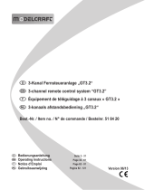
Antenna top
Caution to install the receiver antenna
Never cut, lengthen or bind the antenna wire as the
wavelength for 2.4GHz is short and it is very sensitive to the
length of antenna wire.
Antenna pipe should be put into antenna holder on the
receiver to keep the antenna wire away from metal or
carbon material.
In case the antenna holder is installed outside, it should be
as close to the receiver as possible. If the antenna wire from
receiver to holder is longer, their sensitivity becomes less.
When you put the antenna holder on the metal parts or
carbon chassis, do not put the antenna wire directly on the
metal or carbon.
Antenna lead should be put into antenna pipe for
protection.
Please use plastic antenna pipe so that antenna wire can
keep straight.
Do not put the antenna wire near electric conductors such
as metal or carbon, it causes less sensibility due to
interference.
Especially, such as right illustration, antenna wire should
be installed more than 30mm away from the electric
conductor.
Also note that the middle part of the antenna wire should
not be close to the metal or carbon.
Receiver PCB
E
0
Install the receiver at upper side
of the mechanical plate
8
www.tamico.de
I
NOR
L
^
NOR
AT V
R
I 1 C
I
Steering AN
angle of each direction
9
running of your model.
I NOR
STRATE
1
_
I
11
1
maximum angle
FUNCTION SETTING
BEFORE SETTING
Set up the model before driving.
To change the transmitter settings,always stop the engine first and disconnect the motor wire.
When each lever, dial or button is operated, each function will be indicated on the LCD screen automatically and
you can check the present position and value. The screen will return to the first in 3 seconds after you stop the
operation.
Pay attention to linkage to servos on R/C cars. If the servo function is forced to stop this may cause excess
current to build which will shorten servo life. Adjust with steering rate and steering ATV.
MEMORY CHANGE
This product can memorize set up data for up to 10 cars.
To change the set up memory, follow the procedure below :
1
Push the memory button for more than 2 seconds, the momery change screen will be
indicated with an alarm sound.
2
While the memory change screen is indicated, push the button to override the set up
in the memory.
3
The new memory set up is confirmed automatically after a few seconds.
When you set the data once, do not use this data for other R/C car.
FUNCTIONS OF STEERING TRIM LEVER
Memory change screen
I
U
current memory number
Leave the steering wheel in the neutral position and adjust the trim lever in order to set
up desired neutral position on the servo.
LCD will indicate 0-80 for L/R. This function ensures that the steering linkage does not
lock.
Steering trim
Moving direction and amount of trim
RIGHT AND LEFT ANGLE ADJUSTMENET FUNCTION ( STEERING ATV )
Hold the wheel to full lock right and operate the ATV lever. Repeat this for full left lock.
LCD will indicate -100.
This function ensures that the steering linkage does not lock.
FUNCTION OF STEERING RATE LEVER
You can adjust the maximum rudder angle of the steering servo to ensure optimum
Steering rate
www.tamico.de
Throttle trim
FUNCTIONS OF THROTTLE TRIM LEVER
When operatiang this lever
without
holding the trigger, you can adjust the neutral
position or stopping position. LCD will indicate 0-80 for L/R.
moving direction
and amount of trim
FORWARD AND REVERSE ANGLE ADJUSTMENT FUNCTION ( Throttle ATV )
Throttle AN
Servo turning
direction and angle
CHANGE SERVO ROTATION DIRECTION ( Servo reverse )
Servo rotation can be fixed.
With the steering ATV, throttle
ATV function,
operate the lever until the lowest figure will
be reached. Keep pressing the
lever for
2-3 minutes, then LCD screen will automatically
show "NOR-REV"and servo
rotation will be
switched from NOR to REV with the sound.
According to the linkage
condition,
as excess power will be given on the servo,
ensure that this oepration
is made with
the power switch off.
MEMORY CLEAR
Return the memory to the first setting figure.
Push the memory button for more than 2 seconds with keeping the wheel full lock
right, and the trigger full lock to forward, then screen will indicate " CL "
Release the wheel and trigger and push the memory button more than 2 seconds,
then memory become clear and return to the first setting figure.
BATTERY ALARM
When the battery voltage becomes
low
during
operating, LCD
screen will flash and an
alarm sounds. When this happens, please change the batteries to new ones. The alarm
will continue to sound if you don't change the batteries.
Hold the trigger to the
forward
position or reverse at maximum and then release it
to the stop position.
Operate
this lever to adjust the limits of the servo movement
in each direction.LCD
will indicate
0130.
Clear display
1
0
www.tamico.de
Used correctly, domestic batteries are a safe and dependable source of
portable power. Problems can occur if they are misused or abused —
resulting in leakage or, in extreme cases, fire or explosion
Here are some simple guidelines to safe battery use designed to
eliminate any such problems.
BATTERY
SAFETY
GUIDELINES
Take care to fit your batteries
correctly, observing the plus and
minus marks on the battery and
appliance.
Replace
the whole set of batteries at
one time, taking care not to mix old
and new batteries or batteries of
different types.
Store
unused batteries in their
packaging and away from metal
objects which may cause a short-
circuit.
Remove dead batteries from
equipment and all batteries from
equipment you know you are not
going to use for a long time.
Otherwise the batteries may leak
and cause damage.
Never
dispose
of
batteries in fire as
this may cause them to explode.
Please put dead batteries in with
the normal household waste.
Never attempt to recharge ordinary
batteries, either in a charger or by
applying heat to them. There are
special rechargeable batteries
which are marked as such.
Supervise
children if they are
replacing batteries themselves in
order to ensure these guidelines
are followed.
Make sure battery compartment
are secure.
Supervise children it
they are replacing
batteries themselves in order to ensure
these guidelines are followed.
www.tamico.de
  • Page 1 1
  • Page 2 2
  • Page 3 3
  • Page 4 4
  • Page 5 5
  • Page 6 6
  • Page 7 7
  • Page 8 8
  • Page 9 9
  • Page 10 10
  • Page 11 11
  • Page 12 12
  • Page 13 13
  • Page 14 14
  • Page 15 15
  • Page 16 16
  • Page 17 17
  • Page 18 18
  • Page 19 19
  • Page 20 20
  • Page 21 21
  • Page 22 22
  • Page 23 23
  • Page 24 24
  • Page 25 25

Acoms Technisport 2.4G User manual

Category
Remote controlled toys
Type
User manual

Acoms Technisport 2.4G is a next-generation radio control system designed for ground models, offering precise control and advanced safety features. With its 2.4GHz frequency band and 40 available channels, it eliminates the need for crystals and ensures interference-free operation. The system boasts a compact and lightweight receiver, making it ideal for various model types. It features adjustable steering rate and trim settings for personalized control, allowing you to fine-tune your driving experience.

Ask a question and I''ll find the answer in the document

Finding information in a document is now easier with AI

in other languages