
B
7821
5463
ASSEMBLY INSTRUCTION
etherCON CAT6A Chassis Connector
|
R
Page 1BDA 430
A
B
1.
2.
3.
4.
A
B
C
543
21
6
78
A
max. 8 mm
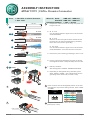
1. Prepare the cable as shown and strip the jacket at a
length of 35 mm.
2. A. S / FTP
Cut off braided shield to approx 20 mm and fold the
shield backwards.
B. U / FTP
Remove the foil of the paired wires and bend back
the drain wire for easier handling during assembly.
Drain wire to be used for grounding.
C. SF / UTP
Cut off braided shield to approx 20 mm and fold the
shield backwards. Cut and remove the foil screen.
3. Remove the pair screening (if existing) to max. 6 mm.
4. Presort, untwist and straighten the wires as shown.
Unstraightened wires could potentially harm the IDC.
A
B
Insert the wires into the designated position of the wire
management as per below wiring scheme, either T568A
or T568B.
Color code RJ 45
PIN No.
Connection
W - G
G
W - O
BL
W - BL
O
W - BR
BR
DD
W - O
O
W - G
BL
W - BL
G
W - BR
BR
T568A T568B
Component
side!
1
2
3
4
5
6
7
8
CC
Wrap the braided shield or drain wire around the cable
jacket (max. 8 mm).
1. Delivery condition:
Wire management T568A & T568B disassembled.
2. Depending on designated wiring standard, press
either T568A or T568B – wire management into the
grounding sheet metal until you hear a snap.
7821
5463
A
T568A
B
7821
5463
5 4 6 3
7 8 2 1
1. 2.
SNAP
B
7821
5463
T568B
35 mm
6 mm
S / FTP
U / FTP
SF / UTP
20 mm
20 mm
Tools: HX-CAT6A or Parallel Presstooll
Side cutterl
Wire size: Solid: AWG 26/1 - AWG 22/1
Stranded: AWG 26/7 - AWG 22/7
Insulation Diameter: > 0.85 - 1.60 mm

etherCON CAT6A Chassis - ASSEMBLY INSTRUCTION
E
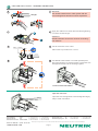
Apply the cable tie for strain relief and after tightening
cut off the excess length.
Attention:
Braided shield or drain wire must be covered by
the cable tie.
543
21
6
78
A
F
Cut all wires with a wire cutter.
Allow wires to protrude max. 0.5 mm.
Use Neutrik's HX-CAT6A or a similar parallel press
plier with smooth (non-serrated) jaws to press the wire
management block and the housing together.
Open the connector:
Open the wire management via the designated lug by
help of a flat screwdriver.
Finished etherCON CAT6A:
E
F
G
max. 0.5 mm
1.
2.
Straight
45° 90°
Attention:
The distance between the cable jacket and the
wire management shall be as short aspossible.
G
HH
43
6
5
543
21
6
78
A
Page 2
Draft. Nr.: BDA 430 Update: 2021-07-06
I I
www.neutrik.com
Neutrik AG LI T: +423 / 237 24 24 F: +423 / 232 53 93
Neutrik USA Inc. USA T: +1 704 / 972 3050 F: +1 704 / 438 9202
( )
Neutrik UK Ltd. UK T: +44 1983 / 811 441 F: +44 1983 / 811 439
Neutrik Vertriebs GmbH DE / NL / AT/DK T: +49 8131 / 280 890 F: +49 8131 / 280 830
Neutrik France FR T: +33 1 / 4131 6750 F: +33 1 / 4131 0511
Neutrik Tokyo Ltd. JP T: +81 3 / 3663 4733 F: +81 3 / 3663 4796
Neutrik Hong Kong Ltd. HK T: +852 / 2687 6055 F: +852 / 2687 6052
R
Data subject to change without prior notice. 2021 NEUTRIK . NEUTRIK are registered trademark of Neutrik AG. ALL RIGHTS RESERVED.
® ®
©
-
 1
1
-
 2
2


Neutrik etherCON CAT6A Chassis Connector Assembly Instruction
- Type
- Assembly Instruction
- This manual is also suitable for
Ask a question and I''ll find the answer in the document
Finding information in a document is now easier with AI
Related papers
-
Neutrik CONN273 User guide
-
-
-
-
-
-
Neutrik BDA 648 V1 etherCON Magnetics User manual
-
-
-
Other documents
-
 Rean RT4MC-B Operating instructions
-
Martin MAC Aura XB User manual
-
Martin Atomic Colors User manual
-
Renkforce 24 ports Network patch panel CAT 6A 1 U Owner's manual
-
-
-
PRESONUS Worx Control User manual
-
Electro-Voice RCM-26 Owner's manual
-
Crestron DM-CONN-ULTRA-PLUG-20 Quick Start
-
PROEL PC260 User manual
