ESCALADE Mizerak P0900 Assembly Instruction Manual
- Type
- Assembly Instruction Manual

1
U N I V E R S A L B I L L I A R D
A C C E S S O R Y D R A W E R
P0900-00
2014 Escalade Sports
MODEL NO.
P0900
A S S E M B L Y I N S T R U C T I O N S
Escalade® Sports products may be manufactured and/or licensed under the following patents.
6120397, 5816957, 5769744, 5119741, 4911085, 4717157, D460140, D420563, 8414431
Additional patents may be pending. One or more of the listed patents and/or pending patents may cover specific product.

2
Contact Escalade® Sports customer service department at:
Phone: 1-800-467-1245 Toll – Free !
Fax: 1-866-873-3533 Toll – Free !
E-mail: Pooltables@escaladesports.com
Mailing Address (correspondence only):
Escalade Sports
PO Box 889
Evansville, IN 47706
1. Read this manual carefully before starting assembly. Read each step completely before beginning each step.
2. Some smaller parts may be shipped inside larger parts. Check inside all parts and cartons before assembling or ordering
parts.
3. To make assembly easier, use the Hardware Identifier on page 3 to identify and sort all fasteners. Check all cartons for kits. All
hardware may not be located in one kit.
4. Do not tighten hardware until instructed to do so. If hardware is tightened too soon, mounting holes may not align and parts
may not easily fit together. Leave locknuts slightly loose until you are instructed to tighten them.
5. Tools required for assembly: Tape Measure, Carpenter’s Square, Sharpie Marker, one 5/16” Wrench or 8 mm Wrench, 7/64” Drill Bit and
Cordless Drill. Note: Ratchet and Socket can be substituted for open end wrenches. A portable light or lamp is also helpful to see under table.
6. Save these instructions and your proof of purchase (receipt) in the event that the manufacturer has to be contacted for
replacement parts.
Please Do Not Return This Product To The Store!
Please visit our Website at:
www.escaladesports.com
ON-LINE TROUBLE SHOOTING TECHNICAL ASSISTANCE
ON-LINE PARTS REQUESTS FREQUENTLY ASKED QUESTIONS
ADDITIONAL ESCALADE®
SPORTS PRODUCT INFORMATION
P R E - A S S E M B L Y T I P S
2014 Escalade Sports
A S S E M B L Y T I P S

3
Drawer, Billiard Accessory
Hanger
Connector
Mounting Rail
Mounting Frame
Drawer Decal Sheet
#10 X 1" Long, Hex Washer Head Sheet Metal Screw
#8-32 Serrated Flange Hex Nut
Instruction Manual
P0900-P1
P0900-P2
P0900-P3
P0900-P4
P0900-P5
P0900-P6
P0900-H1
P0900-H2
P0900-M1
P1
P2
P3
P4
P5
P6
H1
H2
M1
Key# Description
Replacement Parts List for Model Number P0900
Part # Qty.
1
4
4
2
1
1
4
20
1
Part H2
Qty. 20
HARDWARE IDENTIFIER:
P5
P4
P6
H1
H2
P3
P2
P1
Part H1
Qty. 4

4
PLEASE LOOK AT YOUR TABLE AND DETERMINE THE POSITIONING OF YOUR BEAMS.
INSTALLATION WILL DEPEND ON THE TYPE OF BEAM SUPPORTS YOU HAVE ON YOUR
POOL TABLE. IF THE BEAMS RUN THE WIDTH OF THE TABLE SEE PICTURE A. IF THE
BEAMS RUN THE LENGTH OF YOUR TABLE SEE PICTURE B.
B
IF THE BEAMS RUN THE LENGTH OF
THE TABLE LIKE IN PICTURE B SKIP TO
PAGE 16 AND FOLLOW THOSE
DIRECTIONS TO INSTALL YOUR
ACCESSORY DRAWER.
A
IF BEAMS RUN THE WIDTH OF THE TABLE LIKE
IN PICTURE A GO TO THE NEXT PAGE AND
FOLLOW THOSE DIRECTIONS.

5
OVERVIEW OF INSTALLATION PROCEDURE:
BOTTOM EDGE
FRONT OF
DRAWER
4”
20”
location of the first
row of mounting holes
location of the Second
row of mounting holes
BEAM
SUPPORT
DETERMINE IF YOU WANT YOUR
DRAWER TO BE FLUSH TO
THE SIDE APRON OR
RECESSED.
SIDE VIEW
OF TABLE
BOTTOM VIEW
OF TABLE
Beam Support
on your table
Beam Support
on your table
THE FRONT OF DRAWER
WILL GO ON THIS SIDE
OF THE TABLE
Please look at the pictures below and familiarize yourself with your pool table
and which side of the table you want to attach your accessory drawer to. When
fully assembled the Drawer should be flush to the bottom edge of the Side
Apron of your table (unless you want the Drawer recessed), this is why its
important to measure accurately before pre-drilling your holes. Continue to the
next page to start assembly, you will need a cordless drill, a 7/64” drill bit a
tape measure and a fine tip marker such as a Sharpie.
NOTE:
OF SIDE APRON

6
BOTTOM VIEW
OF TABLE
OF SIDE APRON
BEAM
SUPPORTS
16”
1. Determine which side of your pool table you want to attach your Accessory Drawer
and how far in (recessed) from the bottom edge of Side Apron.
1
Figure
2. Measure 4” from the outside of the front face of the Drawer to the center of the
Beams on your table. Mark the location of where you will drill the pilot holes,
making sure hole marks are parallel to each other. See Figure 1.
3. Measure 20” from the outside of the Front of the Drawer (or 16” from the first set
of holes) to the center of the Beams. Mark the location of where you will drill the
pilot holes, making sure hole marks are parallel to each other. See Figure 1.
4. Double check the makings for the pilot holes before drilling. Hole markings must
be centered and square to other hole markings for proper drawer alignment.
Using a 7/64” bit, drill pilot holes about 1” deep into the Beam supports, keep
Drill straight when drilling so pilot hole is as straight as possible.
BOTTOM EDGE
FRONT OF
DRAWER
4”
20”
location of the first
row of mounting holes
location of the Second
row of mounting holes
BEAM
SUPPORT
SIDE VIEW
OF TABLE
OF SIDE APRON
FRONT OF
DRAWER
DETERMINE IF YOU WANT YOUR
DRAWER TO BE FLUSH TO
THE SIDE APRON OR
RECESSED.
NOTE:
4”
20”
BOTTOM EDGE

7
(MOUNTING RAIL)
P4
2
Figure
THREADED
STUDS
THREADED
STUDS
(MOUNTING SLOTS)
5. Become familiar with Mounting Rail P4. Different mounting
slots will be used depending on the distance between your
Beam supports. You will attach screws H1 through the
mounting slots and into the pre-drilled holes you made in the
previous step. The threaded studs will be facing toward the
back when attached to the pool table Beams in the next step.
See Figure 2.
(MOUNTING SLOTS)
Note: H1 Screws will attach
from the bottom in the
next step.
6. You will need two P4 Rails and four H1 Screws for the next
step.

8
Threaded studs on P4 Rail
must be facing toward the
back as shown.
SIDE VIEW
OF TABLE
3
Figure
BEAM
SUPPORTS
THE FRONT OF
DRAWER WILL
GO ON THIS SIDE
BOTTOM VIEW
OF TABLE
THE FRONT OF
DRAWER WILL
GO ON THIS SIDE
DETAIL A
Threaded studs on P4 Rail must
be facing toward the back.
Threaded studs on P4 Rail
must be facing toward the
back as shown.
Threaded studs on P4 Rail must
be facing toward the back.
P4
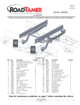
7. Attach Mounting Rails P4, to the support Beams with four H1 screws. Attach
screws H1 through the mounting slots and into the pre-drilled holes you made,
check to make sure Mounting Rails square, straight and centered on beams
before tightening, DO NOT over-tighten screws. The threaded studs should
be facing toward the back. See Figure 3, Detail A & Side View.
BEAM
SUPPORTS
CAUTION:
DO NOT OVER TIGHTEN SCREWS! BECAUSE YOU COULD STRIP SCREWS
IN THE WOOD BEAMS DOING IRREPARABLE DAMAGE TO THE TABLE.
H1
H1

9
TOP VIEW
NOTE: MAKE SURE
THIS EDGE IS
FACING UP
4
Figure
PARTS NEEDED:
1 - (P5) Mounting Frame
8. Fold Mounting Frame P5 so that the noted threaded studs face out as
shown in Figure 4 & the Top View.
P5
Threaded
studs
Threaded
studs
Threaded
studs
Threaded
studs
Threaded
studs
Threaded
studs
Threaded
studs
Threaded
studs
P5

10
NOTE: P3 Connector
can extend on slider
along the slot on P2.
5
Figure
P2
P3
H2
DETAIL B
P3
P2
P3
P2
9. Attach P2 hanger to P3 Connector with H2 Hex nut as shown in Figure 5. Leave nut
H2 loose enough for P3 to slide freely on P2. See Detail B. Repeat step for the
remaining P2 & P3 parts.
PARTS NEEDED:
4 - (P2) Hanger
4 - (P3) Connector
4 - (H2) Hex Nut
Stud
Threaded

11
6
Figure
Threaded Studs on P4 Rail that
you assembled in Step 7 will go
in these holes in the next step.
10. Attach Hanger assemblies to the threaded studs on Mounting Frame P5 with
Hex Nuts H2 as shown in Figure 6.
PARTS NEEDED:
1 - (P5) Mounting Frame
4 - Hanger assemblies
8 - (H2) Hex Nuts
Hanger
Assembly
H2
H2
Hanger
Assembly
H2
Hanger
Assembly
Hanger
Assembly
H2
P5

12
7
Figure
Mounting Frame Assembly
from previous page.
11. Attach Mounting Frame Assembly from Step 10 to the threaded studs on P4
Rails that were installed in Step 7. Use Hex Nuts H2 to secure assembly as
shown in Figure 7 and Detail C.
PARTS NEEDED:
1 - Mounting Frame Assembly
4 - (H2) Hex Nuts
DETAIL C
P4 Rails
P4 Rails
H2
H2
THE FRONT OF DRAWER
WILL GO ON THIS SIDE
OF THE TABLE
THE FRONT OF DRAWER
WILL GO ON THIS SIDE
OF THE TABLE

13
8
Figure
PARTS NEEDED:
1 - (P1) Drawer Assembly
2 - (H2) Hex Nuts
11. Attach Drawer Assembly by the threaded studs to the side hanger
assemblies with two H2 Hex Nuts. See Figure 8 & Detail D.
H2
Hanger
Assembly
P1
H2
Hanger
Assembly
P1
DETAIL D
THE FRONT OF DRAWER
WILL GO ON THIS SIDE
OF THE TABLE

14
9
Figure
PARTS NEEDED:
1 - (P1) Drawer Assembly
2 - (H2) Hex Nuts
12. Attach Drawer Assembly by the threaded studs to both end hanger
assemblies with two H2 Hex Nuts. See Figure 9.
THE FRONT OF DRAWER
WILL GO ON THIS SIDE
OF THE TABLE
Hanger
Assembly
H2
NOTE: Hanger Assembly
can extend
DETAIL E
Congratulations your assembly is complete!
13. Adjust height of your drawer to the desired height with the four Hanger
assemblies, making sure that drawer is level and that there is enough clearance
to open and close drawer. Once drawer is at the desired height tighten the
height adjustment nuts on the Slider Assemblies to hold drawer at that height.
Do a final check of all fasteners to ensure all are tight. See Detail E.
Height
Adjustment
nut

15
PLEASE LOOK AT YOUR TABLE AND DETERMINE THE POSITIONING OF YOUR BEAMS.
INSTALLATION WILL DEPEND ON THE TYPE OF BEAM SUPPORTS YOU HAVE ON YOUR
POOL TABLE. IF THE BEAMS RUN THE WIDTH OF THE TABLE SEE PICTURE A. IF THE
BEAMS RUN THE LENGTH OF YOUR TABLE SEE PICTURE B.
B
IF THE BEAMS RUN THE LENGTH OF THE TABLE
LIKE IN PICTURE B CONTINUE TO THE NEXT
PAGE AND FOLLOW THOSE DIRECTIONS TO
INSTALL YOUR ACCESSORY DRAWER.
A
IF BEAMS RUN THE WIDTH OF THE TABLE LIKE
IN PICTURE A GO BACK TO PAGE 5 AND
FOLLOW THOSE DIRECTIONS.

16
TOP VIEW
NOTE: MAKE SURE
THIS EDGE IS
FACING UP
1
Figure
PARTS NEEDED:
1 - (P5) Mounting Frame
1. Fold Mounting Frame P5 with the noted threaded studs facing out as
shown in Figure 1 & the Top View.
P5
Threaded
studs
Threaded
studs
Threaded
studs
Threaded
studs
Threaded
studs
Threaded
studs
Threaded
studs
Threaded
studs

17
NOTE: P3 Connector
can extend on slider
along the slot on P2.
2
Figure
P2
P3
H2
DETAIL A
P3
P2
P3
P2
2. Attach P2 hanger to P3 Connector with H2 Hex nut as shown in Figure 2. Leave nut
H2 loose enough for P3 to slide freely on P2. See Detail A. Repeat step for the
remaining P2 & P3 parts.
PARTS NEEDED:
4 - (P2) Hanger
4 - (P3) Connector
4 - (H2) Hex Nut
Stud
Threaded

18
3
Figure
3. Attach Hanger assemblies from Step 2 to the threaded studs on Mounting
Frame P5 with Hex Nuts H2 as shown in Figure 3.
PARTS NEEDED:
1 - (P5) Mounting Frame
4 - Hanger assemblies
8 - (H2) Hex Nuts
Hanger
Assembly
H2
H2
H2
Hanger
Assembly
Hanger
Assembly
H2
P5
NOTE: MAKE SURE
THIS EDGE IS
FACING UP
Hanger
Assembly

19
Mounting Screws will go in these
holes when mounting the frame
to the Beams on the table.
NOTE: SIDE WITH
SLOTTED HOLES
FACES UP
Threaded
studs.
Threaded
studs.
H2
P4
P4
NOTE: SIDE WITH
SLOTTED HOLES
FACES UP
4
Figure
H2
PARTS NEEDED:
1 - Mounting Frame Assembly
2 - (P4) Mounting Rail
4 - (H2) Hex Nuts
4. Attach P4 Mounting Rails to Mounting Frame assembly from Step 3. Insert
Threaded Studs in the P4 Rails through the Mounting assembly and secure
with Hex Nuts H2 as shown in Figure 4.

20
BOTTOM VIEW
OF TABLE
SIDE APRON
BEAM
SUPPORTS
5. Determine which side of your pool table you want to attach your
Accessory Drawer.
5
Figure
6. Determine where the middle of the table is and mark a centerline on the
inside of the first Beam Support. Measure 17.5” to either side from
the centerline and 3/8” in from inner face of Support Beam and mark
first hole location. Measure 35” from the first hole location and mark
the second hole location as shown in Figure 5.
7. Mark the third hole location to the center of the Second Support Beam
exactly straight across from the first hole Mark. Repeat for fourth hole
location but with Second hole mark. See Figure 5.
8. Using your Mounting Frame double check that the makings for the pilot
holes line up before drilling. Hole markings must be centered and
square to other hole markings for proper drawer alignment. Using a
7/64” bit, drill pilot holes about 1” deep into the Beam supports, keep
Drill straight when drilling so pilot hole is as straight as possible.
Mounting
frame
assembly
Match these holes up with the
hole mark on the Support Beams
before drilling any holes.
This face should be flush
against the inner part of
the first Support Beam.
35” Center line
Mark the Center
line on the inside
of the first Beam
Mark second
hole location
Mark first
hole location
3/8”
first hole location
mark should line
up with this hole
Second hole
location mark should
line up with this hole
Mark third
hole location
Mark fourth
hole location
Third hole location
should line up with any
of these slots
Fourth hole location
should line up with any
of these slots
Second Beam
Center line
Page is loading ...
Page is loading ...
Page is loading ...
Page is loading ...
-
 1
1
-
 2
2
-
 3
3
-
 4
4
-
 5
5
-
 6
6
-
 7
7
-
 8
8
-
 9
9
-
 10
10
-
 11
11
-
 12
12
-
 13
13
-
 14
14
-
 15
15
-
 16
16
-
 17
17
-
 18
18
-
 19
19
-
 20
20
-
 21
21
-
 22
22
-
 23
23
-
 24
24


ESCALADE Mizerak P0900 Assembly Instruction Manual
- Type
- Assembly Instruction Manual
Ask a question and I''ll find the answer in the document
Finding information in a document is now easier with AI
Related papers
Other documents
-
 Global Contract Bridges II Installation guide
-
Stiga ST3100 Assembly Instructions
-
Panduit Net-Contain Installation guide
-
-
 Air Lift Performance 39020 ECR 6107 User manual
-
Air Lift Performance 39010 User manual
-
 Friant & Associates Interra Installation guide
-
 NewAge Products Inc. 40406 User guide
-
 Air Lift Performance MN-643 User manual
-
 NewAge Products Inc. 40400 User guide


