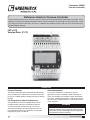
Greenheck 483843 Furnace Controller v1.03 March 2019 Operating instructions
- Type
- Operating instructions
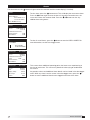
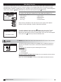
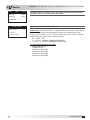
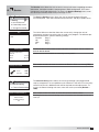
Greenheck 483843 Furnace Controller v1.03 March 2019 offers advanced control through easy monitoring and adjustment of furnace parameters via a lighted graphical display and push-button keypad. It monitors furnace operations for alarm conditions and records alarm description, time, date, available temperatures, and furnace status. The controller is pre-programmed with multiple control sequences to provide tempered air, with factory default settings allowing for easy setup and commissioning.
Greenheck 483843 Furnace Controller v1.03 March 2019 offers advanced control through easy monitoring and adjustment of furnace parameters via a lighted graphical display and push-button keypad. It monitors furnace operations for alarm conditions and records alarm description, time, date, available temperatures, and furnace status. The controller is pre-programmed with multiple control sequences to provide tempered air, with factory default settings allowing for easy setup and commissioning.


-
 1
1
-
 2
2
-
 3
3
-
 4
4
-
 5
5
-
 6
6
-
 7
7
-
 8
8
-
 9
9
-
 10
10
-
 11
11
-
 12
12
-
 13
13
-
 14
14
-
 15
15
-
 16
16
-
 17
17
-
 18
18
-
 19
19
-
 20
20


Greenheck 483843 Furnace Controller v1.03 March 2019 Operating instructions
- Type
- Operating instructions
Greenheck 483843 Furnace Controller v1.03 March 2019 offers advanced control through easy monitoring and adjustment of furnace parameters via a lighted graphical display and push-button keypad. It monitors furnace operations for alarm conditions and records alarm description, time, date, available temperatures, and furnace status. The controller is pre-programmed with multiple control sequences to provide tempered air, with factory default settings allowing for easy setup and commissioning.
Ask a question and I''ll find the answer in the document
Finding information in a document is now easier with AI
Related papers
-
Greenheck 481155 Furnace Controller IGF v1.00 Operating instructions
-
-
-
-
-
-
-
-
-
Greenheck 485931 User guide
Other documents
-
Bard Thermostat User manual
-
 ThermoMart DWH7016V Owner's manual
-
Bard 8403-060 User manual
-
Johnson Controls 100 Series Installation Operation & Maintenance
-
 MRC E5CC User manual
-
Bryant EVOLUTION Zone Control SYSTXBBUIZ01-B Installation Instructions Manual
-
Johnson Controls GVC Series Start-Up & Operation
-
Lennox International Inc. icomfort Wi-Fi User manual
-
SSI America Washer/Dryer 9210 User manual
-

