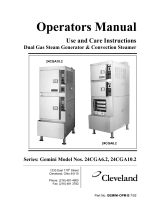
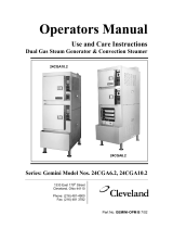
Cleveland 24-CEA-10 User manual

Type
User manual

This manual is also suitable for

Cleveland Range
SteamCraft 10®
Convection Steamer
MODELS: 24-CEA-10, & 24-CGA-10
Cleveland Range, Inc.
SERVICE
MANUAL
Printed 3/93
UNITED STATES
1333 East 179th St.. Cleveland, Ohio 44110 Phone: (216) 451-4900 •
Telex: 98-0546 • FAX: (216) 481-3782
CANADA
Garland Commercial Ranges
1177 Kamato Road
Mississaugha, Ontario. Canada L4W1X4
Phone: (416) 624-0260 - FAX: (416) 624-0623
FOR YOUR SAFETY
Do not store or use gasoline or other flam-
mable vapors or liquids in the vicinity of this
or any other appliance.
GAS LEAK INSTRUCTIONS
Post in a prominent location, instructions
to be followed in the event the user smells
gas. This information shall be obtained by
consulting the local gas supplier.
For safe and efficient operation of this equipment, this manual must be retained by the owner/user
for future reference.
PROTECTING WARRANTY COVERAGE
The warranty printed to the left specifies the owner/user's responsibility for proper installation, operation,
and maintenance of the SteamCraft 10. If these responsibilities are not met, toe Limited Warranty and/or
Extended Limited Warranty coverage may be adversely affected. The following table is provided to assist
the owner/user in meeting these responsibilities. In addition, the warranty advantages of installing a
SteamerGard water treatment system are explained after the table.
The Warranty Protection Table lists installation, operation, and maintenance factors that have in the past
adversely affected warranty coverage. The owner/user of a SteamCraft 10 should pay particular attention
to these factors to protect his warranty coverage. This table is not a comprehensive list of the owner/user's
responsibilities. Cleveland Range steam products are intended for use only by professionally trained
personnel To meet his responsibilities, the owner/user must supplement this guide with any additional
actions consistent with the operation of steam generating food preparation equipment by a trained
professional.
Warranty Protection Table
SUBJECT PAGE
REFERENCE
Electrical Power Requirements & Line Voltage 10
Water Quality Requirements & Analysis 11
Water Pressure 16
Vented Drain 20
Level Operation 19
Blowdown Frequency 55 & 63
Steam Generator Maintenance & Maintenance Records 67
Descaling Frequency & Procedure 68
Approved Chemical Cleaners 68
Authorized Maintenance & Repair 74
SteamerGard Water Treatment System
A SteamerGard water treatment system protects the SteamCraft 10 from impurities contained in regular
lap water, especially Total Dissolved Solids (TDS) which cause lime and scale deposits in steamer
equipment. The protection is so effective that Cleveland Range increases toe warranty coverage on a
Steam Craft 10 installed in conjunction with a SteamerGard system to five years for parts and three years
for labor on water related components, elements, valves, generators, piping, etc. However, even with a
SteamerGard system installed, the owner/user should follow toe guidance of the Warranty Protection
Table.
Models 24-CGA-10 and 24-CEA-10 SteamCraft 10 Service Manual
Table of Contents
Chapter Page
CHAPTER 1. PRODUCT IDENTIFICATION 1
MODEL NUMBER 1
SERIAL NUMBER 1
PRODUCT INFORMATION PLATE 1
CHAPTER 2. INSTALLATION INSTRUCTIONS 7
INTRODUCTION 7
INSTALLATION POLICIES 7
INSTALLATION OVERVIEW 8
PREPARATION FOR INSTALLATION 10
Protecting The SteamCraft 10 10
Electric Power Requirements 10
Gas Supply Requirements 10
Exhaust Hood Requirements – All Models 10
Water Quality Requirements 11
Softened, Treated, or Filtered Water 16
Water Supply System 16
Selecting The Operating Location 17
INSTALLATION INSTRUCTIONS 18
Unpacking & Inspection 18
Shipping Damage Instructions 19
Position & Level The SteamCraft 10 19
Adjustable Leveling Legs 19
Positioning & Leveling 19
Install Slide Racks 20
Install & Connect The Free Air Vented Drain Lines 20
Exhaust Hood Ventilation – All Models 22
Install Electric Power Lines 22
Connect Electrical Line 23
Install Water Supply Lines 24
Connect Water Supply Lines 26
General Connection Requirements 26
Untreated Water Connection (Without SteamGard) 27
Treated Water Connection (With SteamGard) 27
Testing Water Supply Lines 27
Install & Connect Gas Supply Lines 27
Leak-Testing Gas Supply Lines 28
Pressure Testing The Gas Supply Lines 29
Bleed Air From The Gas Supply Lines 30
Burner Ignition Test (Gas-Fired Models Only) 31
Final Setup & Checkout 33
Cleveland Range, Inc. Printed 3/93
Page ii SteamCraft 10 Service Manual Models 24-CGA-10 0 and 24-CEA-10
Table of Contents (continued)
Chapter Page
Installation Checks 33
Operating Tests 34
Operating Test Preparation 34
Blowdown Inspection Procedure 35
Operating Test Procedures 35
Timer Test Procedures – Key Pad Control Panel 37
Timer Test Procedures – Dial Timer Control Panel 38
CHAPTER 3. OPERATION 41
INTRODUCTION 41
DIFFERENCES AMONG MODELS 41
Atmospheric Generator Models 41
Pressure Generator Models 41
OPERATIONAL SAFETY 41
BURNER LIGHTING 43
GAS LEAK INSTRUCTIONS 43
OPERATING MODES 43
Manual Operation 43
Timed Operation 43
Manual Timer 43
Steam Generator BlowDown 44
MAIN DISCONNECT SWITCH 44
CONTROL PANELS 44
COOKING OPERATIONS KEY PAD CONTROL PANEL 46
Summary Of Cooking Operations 46
Power ON (Automatic Fill) 47
Start Steam Supply 47
Inspect The Cooking Compartment 47
Preheat The Cooking Compartments 48
Place Food Into The Cooking Compartment(s) 49
Select The Operating Mode 49
Timed Cooking Procedure 50
Manual Cooking Procedure 51
Power OFF (Automatic Blowdown) 52
Blowdown Frequency 52
Blowdown Procedure 53
Shut Down And Cleaning (At End Of Day Or Shift) 53
DIAL TIMER CONTROL PANEL SUMMARY 55
COOKING OPERATIONS – DIAL TIMER CONTROL PANEL 56
Summary Of Cooking Operations 56
Power ON (Automatic Fill) 56
Printed 3/93 Cleveland Range, Inc.
Models 24-CGA-10 and 24-CEA-10 SteamCraft 10 Service Manual Page iii
Table of Contents (continued)
Chapter Page
Start the Steam Supply 57
Inspect the Cooking Compartment 57
Preheat the Cooking Compartment(s) 57
Place Food into The Cooking Compartment(s) 58
Select the Operating Mode 58
Timed Cooking Procedure 58
Manual Cooking Procedure 59
Remove Food from The Cooking Compartment(s) 59
Power OFF (Automatic Blowdown) 60
Blowdown Frequency 60
Blowdown Procedure 60
Shut Down And Cleaning (At End Of Day Or Shift) 61
CHAPTER 4. PREVENTATIVE MAINTENANCE AND TROUBLESHOOTING 63
INTRODUCTION 63
MAINTENANCE RECORDS 63
DAILY MAINTENANCE 63
Blowdown Steam Generator 63
Clean SteamCraft 10 63
WEEKLY MAINTENANCE 63
Clean Drain 63
MONTHLY MAINTENANCE 64
Descale Steam Generator 64
YEARLY MAINTENANCE 67
Clean Water Line Strainer 67
TROUBLESHOOTING NOTES 70
CHAPTER 5. COMPONENT AND CIRCUIT FUNCTIONS 71
INTRODUCTION 71
Models Covered In This Chapter 71
Figures and Illustrations 71
SteamCraft 10 Variations 71
Steam Generator Power Source 71
Control Panel Type 72
THEORY OF OPERATION 72
Steam Generator Water Filling Cycle 72
Steam Generator Preheating 74
Steaming Functions For Model 24-CEA-10 75
Steaming Functions For Model 24-CGA-10 76
Gas Burner Ignition and Combustion Functions – Model 24-CGA-10 79
Burner Ignition and Control System 79
Cleveland Range, Inc. Printed 3/93
Page iv SteamCraft 10 Service Manual Models 24-CGA-10 and 24-CEA-10
Table of Contents (continued)
Chapter Page
Condenser and Drain Functions 80
Condenser Operation 80
Drain Valve Functions 81
Shutdown, Steam Generator And Float Cylinder Rise Functions 82
STEAMCRAFT 10 ELECTRICAL CIRCUITS – Model 24-CEA-10 83
High Voltage Circuit 83
120 VAC Circuit 83
STEAMCRAFT 10 ELECTRICAL CIRCUITS – Model 24-CGA-10 83
STEAMCRAFT 10 TIMER CIRCUITS 84
ELECTRICAL CIRCUIT COMPONENTS 84
Terminal Block 84
ON/OFF Switch 85
TIMED/MANUAL Switch 85
3-Minute Timer 85
Float Assembly 86
Rinse Solenoid Valve 87
Drain Solenoid Valves 87
Water Fill Solenoid Valves 87
Condenser Solenoid Valves 87
Preheat Thermostat 88
Key Pad and Dial Timers 88
Electronic Key Pad Timer 88
Compartment Thermostat (Electronic Key Pad Units Only) 89
Mechanical Timer 89
3-Second Timer And Buzzer (Mechanical Timer Units Only) 89
Heater Element – Model 24-CEA-10 89
Dryer Element – Model 24-CEA-10 89
High Temperature Limit Switch 89
Combustion Control Module – Model 24-CGA-10 90
Combustion Air Blower 90
Air Prover Pressure Switch 90
Pilot Spark Igniter 90
Automatic Gas Valve 90
Steam Relief Solenoid Valve – Model 24-CGA-10 90
Compartment Steam Solenoid Valves – Model-CGA-10 90
CHAPTER 6. COMPONENT TESTING GUIDE 91
INTRODUCTION 91
Models Covered In This Chapter 91
Figures And Illustrations 91
Nominal Voltage Reference 91
Printed 3/93 Cleveland Range, Inc.
Models 24-CGA-10 and 24-CEA-10 SteamCraft 10 Service Manual Page v
Table of Contents (continued)
Chapter Page
COMPONENT TESTING FUNDAMENTALS 92
Visual Check 92
Connections and Wiring 92
Solenoid Valves 93
General Considerations 93
Normally Open And Normally Closed Valves And Contacts 93
Water Pressure and Control Valves 93
Measuring Resistance Through The Solenoid 93
Jammed or Blocked Valves 93
Thermostatic Snap Switches 95
Heater Element 95
Resistance Measurements 95
Insulation Resistance Measurements 96
Voltage Measurements 96
INITIAL TEST PROCEDURE – INTRODUCTION 96
Test Procedures Layout and Conventions 96
INITIAL TEST PROCEDURE – GENERAL PREPARATIONS 97
Model Numbers and Test Procedure Variations 97
INITIAL TEST PROCEDURE – MODEL 24-CGA-10 98
Set Up the Initial Test Conditions 98
COMPONENT TEST PROCEDURES 123
Initial Conditions for All Testing 123
CT:1 Drain (3-Way) Solenoid Valves 123
CT:2 3-Minute Timer 124
CT:3 Rinse Solenoid Valves 125
CT:4 Water Fill Solenoid Valves 126
CT:5 ON/OFF Switch 127
CT:6 Float Assembly 128
CT:7 Gas Control Transformer – 24 Volt Model 24-CGA-10 131
CT:8 Preheat Thermostat (Steam Generator) 131
CT:9 TIMED/MANUAL Switch 132
CT:10 Condenser Solenoid Valves 133
CT:11 Steam Relief Solenoid Valve – Model 24-CGA-10 135
CT:12 Compartment Steam Solenoid Valve – Model 24-CGA-10 136
CT:13 Mechanical Timer 137
CT:14 & CT:15 3-Second Timer And Buzzer (Mechanical Timer Units Only) 137
CT:16 Electronic Timer Transformer – 24 Volt 138
CT:17 Electronic Key Pad Timer 139
CT:18 Compartment Thermostat (Key Pad Timer Units Only) 141
CT:19 Transformer – Model 24-CEA-10 142
CT:20 & CT:21 Heater Contactor – Model 24-CEA-10 142
Cleveland Range, Inc. Printed 3/93
Table of Contents (continued)
Chapter Page
CT:22 High Temperature Limit Switch – Model 24-CEA-10 144
Terminal Block 145
CT:23 & CT:24 Heater & Dryer Elements – Model 24-CEA-10 145
CT:25 Relay R-1 – Model 24-CEA-10 147
Burner Ignition & Control System Components – Model 24-CGA-10 147
CHAPTER 7. ILLUSTRATED PARTS LISTS 149
INTRODUCTION 149
Parts Differences Among SteamCraft 10 Steamers 149
Electrical Schematics And Wiring Diagrams 149
Ordering Parts 149
CHAPTER 8. IGNITION MODULE 199
INTRODUCTION 199
HONEYWELL & WHITE-RODGERS MANUALS 199
Printed 3/93 Cleveland Range, Inc.
Models 24
-
CGA
-
1
0
24
-
CEA
-
10
Steam Craft 10 Service Manual
Models 24-CGA-10, 24-CGP-10, 24-CEA -10, 24-CEP-10 SteamCraft 10 Service Manual, Chapter 1 Page 1
CHAPTER 1. PRODUCT IDENTIFICATION
Cleveland Range, Inc. assigns two product identification numbers to each
SteamCraft 10: a model number and a serial number. The model number
identifies the product characteristics. The serial number identifies the indi-
vidual unit.
MODEL NUMBER
The operating section of this manual (Chapters 1 through 4) covers four
models of the Steam Craft 10 steamers:
• Gas fired atmospheric generator 24-CGA-10
• Gas fired pressure generator. 24-CGP-10
• Electric atmospheric generator. 24-CEA-10
• Electric pressure generator 24-CEP-10
The service section of this manual (Chapters 5 through 8) covers only the
atmospheric models:
• Gas fired atmospheric generator 24-CGA-10
• Electric atmospheric generator. 24-CEA-10
Each character of the model number identifies a characteristic of the
steamer. The Steam Craft 10 is 24 inches wide; a Convection steamer,
Electric or Gas powered, Atmospheric or Pressurized steam generator, and
has the capacity for 10 cooking pans.
This manual covers all standard features and options available on
SteamCraft 10 steamers. Other than selection of options, there are
presently no significant design, parts, or operating differences among
steamers with the same model number. Figure 1-2, Sheets 1 through 4
illustrate the four SteamCraft 10 models and identify the major components.
SERIAL NUMBER
During manufacture, SteamCraft 10's are assigned individual serial num-
bers. A typical SteamCraft 10 serial number is: WC-7350-90G-02. The left
half of the number carries design information. The right half of the number
contains the manufacturing date and the unit of the manufacturing lot The
date of our sample number is 90G-02:90=1990, G=July. 02=the second unit
of the manufacturing lot Serial numbers arc used when explaining differ-
ences in design, parts, or operation among units with the same model
number. For example: a particular part may be used on SteamCraft 10's
with serial numbers before WC-7350-90G-02, and a different part used on
steamer WC-7350-90G-02 and those manufactured after it.
PRODUCT INFORMATION PLATE
The Product Information Plates list the unit's model and serial numbers, and
power and wiring requirements. These plates are located on the left side
panel, in the lower right corner. Figure 1-1 illustrates typical SteamCraft 10
Product Information Plates. Refer to me Figure 1-2 for the location of the
plates.
Page 2 Chapter 1, SteamCraft 10 Service Manual Models 24-CGA-10, 24-CGP-10, 24-CEA-10, 24-CEP-10
Figure 1-1. SteamCraft 10 Product information Plates
Printed 3/93 Cleveland Range, Inc.
Models 24-CGA-10, 24-CGP-10, 24-CEA-10, 24-CEP-10 SteamCraft 10 Service Manual, Chapter 1 Page 3
Figure 1-2. SteamCraft 10, Models 24-CGA -10 and 24-CEA-10
with Key Pad Control Panel (Sheet 1 of 4)
Cleveland Range, Inc. Printed 3/93
Figure 1-2. SteamCraft 10, Models 24-CGP-10 and 24-CEP-10
with Key Pad Control Panel (Sheet 2 of 4)
Printed 3/93 Cleveland Range, Inc.
Chapter
1, SteamCraft 10 Service Manual Models 24-CGA -10, 24-CGP-10, 24-CEA-10, 24-CEP-10 Page 4
Models 24-CGA -10, 24-CGP-10, 24-CEA-10, 24-CEP-10 SteamCraft 10 Service Manual, Chapter 1 Page 5
Figure 1-2- SteamCraft 10, Models 24-CGA -10 and 24-CEA-10
with Dial Timer Control Panel (Sheet 3 of 4)
Page 6 Chapter 1, SteamCraft 10 Service Manual Models 24-CGA-10, 24-CGP-10, 24-CEA-10, 24-CEP-10
Figure 1-2. SteamCraft 10, Models 24-CGP-10 and 24-CEP-10
with Dial Timer Control Panel (Sheet 4 of 4)
Models 24-CGA-10, 24-CGP-10, 24-CEA-10, 24-CEP-10 SteamCraft 10 Service Manual, Chapter 2 Page 7
CHAPTER 2. INSTALLATION INSTRUCTIONS
This manual and several components are packaged inside the Steam Craft 10
shipping carton. Only enough of the carton should be opened to remove this
manual. Do not remove the Steam Craft 10 from the carton until just before
installation. If the shipping carton has already been removed and discarded, protect
the Steam Craft 10 from dirt and damage during storage, site preparation, and
installation as described in Protecting The Steam Craft 10, page 10.
WARNING
DEATH, INJURY, AND EQUIPMENT DAMAGE
could result from improper installation of the
SteamCraft 10, or from installation of a unit dam-
aged during shipment or storage. Either of these
conditions could also void the equipment warranty.
DO NOT INSTALL a SteamCraft 10 suspected of
damage.
Install the SteamCraft 10 according to the policies
and procedures outlined in this manual.
INTRODUCTION
This chapter is a guide for installation of the SteamCraft 10, model numbers 24-
CGA -10,24-CGP-10,24-CEA-10 and 24-CEP-10. This guide is for use by qualified
professionals, and does not include all procedures and precautions in the common
domain of licensed plumbers, pipe fitters, and electricians, or experienced food
service equipment installers. This guide must be used in conjunction with
professional experience and a thorough understanding of the local, state, and
national utility, construction and sanitation codes; the most prominent of which are
listed in the Installation Policies section below.
Before starting installation, the owner and the installer should read through this
chapter and thoroughly understand and agree upon:
• The installation policies of Cleveland Range, Inc. as stated in Installation
Policies.
• An installation plan based on the Installation Overview and Installation Check
List
• Responsibility for feed water quality and its testing as described in Preparation
For Installation, Water Quality Requirements.
INSTALLATION POLICIES
The SteamCraft 10 must be installed by qualified plumbing and electrical
personnel, working to all applicable national and local codes.
• In the U.S.A., equipment installation must comply with the Basic Plumbing
Code of the Building Officials and Code Administrators International, Inc.
(BOCA), the National Fuel Gas Code, ANSI Z223.1-(latest edition), the
National Electric Code, ANSI/NFPA No. 70-(latest edition), and the Food
Service Sanitation Manual of the Food and Drug Administration (FDA).
• In Canada, equipment installation must comply with the CAN/CGA-B 149
Installation Code, the Canadian Electrical Code CSA C221and any other
applicable national and local codes.
Cleveland Range, Inc. Printed 3/93
Previous Page
Page 8 Chapter 2, SteamCraft 10 Service Manual Models 24-CGA -10, 24-CGP-10, 24-CEA-10, 24-CEP-10
• Cleveland Range designs and manufactures equipment ID comply with
applicable standards for manufacturers. Included among these certification
agencies are: UL, A.G.A., ASME/N.Bd., NSF, CSA, CGA, ETL, and
others.
• This equipment is designed and certified for safe operation only when
permanently installed in accordance with local and/or national codes. Many
local codes exist, and it is the responsibility of the owner and installer to
comply with these codes.
• In no event shall the manufacturer assume any liability for damage or injury
resulting from installations which are not in strict compliance with the
Installation Instructions and the codes cited above. Specifically, the
manufacturer will not assume any liability for damage or injury resulting
from improper installation of equipment, including, but not limited to,
temporary or mobile installations.
INSTALLATION OVERVIEW
SteamCraft 10 installation is presented in two parts: preparation and instal-
lation. Table 2-1 and Figure 2-1 provide an overview of installation process.
Figure 2-1, Schematic Installation Diagram, illustrates the utility lines and
connections required to install the SteamCraft 10. The Dimension Drawings,
Figure 2-2, show the required utility connection points, dimensions, and
clearances for each of the SteamCraft 10 models.
Table 2-1, Installation Check: List, outlines the overall installation process by
listing, in recommended sequence, the major tasks to be performed. For each
task the table references applicable notes from Figure 2-1 and the manual
pages on which the task instructions begin. Complete the preparation tasks in
sequence, and then the installation tasks. Installation requirements may vary
from site to site; adapt the check list accordingly.
Table 2-1. Installation Check List
(Refer to Figure 2-1)
TASK FIGURE 2-1
NOTES
PAGE REFERENCE COMPLETED
Preparation
Chec
k electric power requirements.
1
,2
10
Check gas supply requirements (gas models only).
2,3,4
10
Check exhaust hood requirements. 12 10
Test supply water quality.
5,6
11
Select water treatment system.
6
16
Select operating location
-
17
Unpack, inspect, and protect me unit.
18
Installation
Position and level steamer.
11
19
Install and connect drain line. 9,10 20
Install exhaust hood.
12
22
Install and connect electrical line. 1,2 22
Install and connect water supply lines.
5,6,7,8
24
Install water treatment system.
6
26
Test water supply lines.
27
Install and connect gas supply lines (gas models only).
2,3,4
27
Test gas supply lines (gas models only).
28
Bleed gas line at union upstream of gas valve (gas models only) 3 30
Test burner igniter control module (gas models only).
31
Perform final setup and checkout
33
Models 24-CGA-10, 24-CGP-10. 24-CEA -10, 24-CEP-10 SteamCraft 10 Service Manual Chapter 2 Page 9
INSTALLATION DIAGRAM NOTES
1 . For each unit, the installer must provide a ground con-
nection and a separate fused disconnect switch.
2. The Product Identification Plate, located in the lower right
corner of the left side panel, specifies the electric power
and gas utility requirements.
3. A manual shut off valve and a drip leg must be installed
between the main gas supply and the steamer supply
lines- Bleed air from the gas line at the fitting closest to
the internal automatic gas valve. Refer to Figure 2-14 for
the recommended component arrangements.
4. Never exceed 14" water column (1/2 psi) gas pressure. If
the gas supply pressure exceeds 14" water column, a
pressure regulating valve must be installed in the gas
supply plumbing to reduce the gas pressure to less than
14" water column.
5. The unit must have a cold water supply, NOT HOT. The
water supply must meet the quality requirements of
Table 2-2, and the pressure requirements on page 16.
6. A SteamerGard filtering system is recommended when
water quality does not meet the Table 2-2 requirements,
7. Run a single water line between the main cold water supply
and the tee. The two separate steam generator and
condenser/blowdown supply lines are relatively short.
8. A manual shut off valve must be installed between the main
water supply and the steamer supply lines- Refer to Figure
2-10 or 2-11 for recommended component arrangements.
9. The drain line must have a gravity flow away from the
steamer, and must not be connected to the drain lines of any
other equipment.
10. The drain line must be free air vented. If the line empties
into a floor drain, there must be a one inch minimum
clearance between me drain line and the floor drain
openings- The floor drain must not be located under the
body of the unit.
11. To maintain proper operation and full warranty coverage,
the unit must be level from to back and side 10 side.
12. The flue at the back of the gas-fired units must be ventilated
as specified by local and national codes
Figure 2-1. Schematic Installation Diagram
Page 10 Charter 2, SteamCraft 10 Service Manual Models 24-CGA-10, 24-CGP-10, 24-CEA-10, 24-CEP-10
PREPARATION FOR INSTALLATION
Select and prepare the SteamCraft 10 operating location before permanently
positioning the unit. Protect the unit and packaged components during site
preparation. Do not select the operating location or start installation before
checking the electric power, gas, and water quality requirements to assure
proper drainage, ventilation, and safety.
Protecting The SteamCraft 10
Do not remove the SteamCraft 10 from its shipping canon until just before
installation. If me shipping canon has already been removed and discarded,
refer to Unpacking and Inspection on page 18, and inspect me shipment.
Remove the SteamCraft 10 and components from the immediate work area
during storage, site preparation, and while running the utility supply lines to
the operating location. To protect the SteamCraft 10 from dirt, and prevent
loss or damage, take the following precautions as a minimum.
1. Leave packaged components inside the shipping canon or cooking com -
partment.
2. Keep the SteamCraft 10 dean by covering it with a plastic tarp or drop
cloth.
3. Do not store other items on top of the SteamCraft 10.
Electric Power Requirements
The characteristics of me electric power supply must match the power
requirements specified on the SteamCraft 10 product identification plate. The
plate is located on the left side panel, in the lower right comer, as detailed in
Figure 2-2.
Gas Supply Requirements
NEVER EXCEED 14" WATER COLUMN (1/2 psi) GAS PRESSURE. If the
gas supply pressure exceeds 14" water column, a pressure-regulating valve
must be installed in the gas supply plumbing to reduce the gas pressure to
less than 14" water column.
• Natural gas pressure must be between 4" -14" water column.
• L.P. gas supply pressure must be between 12" -14" water column.
Exhaust Hood Requirements
All Models
In addition to the required venting of gas-fired equipment, some state and
local codes require me venting of steam generating equipment. It is the
responsibility of me owner and/or installer to learn and comply with these
codes.
• Models 24-CGA-10 and 24-CGP-10 have gas-fired steam generators with
an exhaust vent on top of the unit These units MUST be installed under an
exhaust hood suitable for ventilation and operation of gas-fired appliances,
as specified by local and national codes.
• Models 24-CEA-10 and 24-CEP-10 have electric steam generators and do
not have an exhaust vent. In some areas, local codes require installation of
these units under an exhaust hood suitable for ventilation and operation of
steam generating appliances.
Models 24-CGA-10, 24-CGP-10, 24-CEA-10, 24-CEP-10 SteamCraft 10 Service Manual, Chapter 2 Page 11
Water Quality Requirements
CAUTION
Using water not within the limits specified in this
manual could void or adversely affect Cleveland
Range's warranty coverage of the SteamCraft 10.
As with any steam generating equipment, poor water quality degrades
SteamCraft 10 performance. If feed water is low in Total Dissolved Solids
(TDS) and free of particulate matter, the steam generator, heating element,
and valves of me Steam Craft 10 will give years of trouble-free service
with a minimum of maintenance.
In some areas, even potable tap water contains a variety of impurities that
can cause costly problems in steam generating equipment. Of primary
concern are mineral salts and other impurities, which remain behind as
lime or scale deposits during the steam generating process. These deposits
have caused components to fail, including nearing elements, probes, and
solenoid valves. Of equal importance is me decrease in heat transfer
efficiency caused by lime and scale deposits. Decreased heat transfer
increases water and power consumption. Use of the SteamCraft 10 in areas
with poor water quality requires installation of a SteamerGard water
treatment system or increased frequency of maintenance, cleaning, and
descaling.
Check the quality of supply water as described below before starting con-
struction of the water supply lines. If a SteamerGard water treatment
system must be installed to achieve acceptable water quality, install it
before connecting the water supply lines to the SteamCraft 10. For more
information on water treatments, refer to Softened, Treated, or Filtered
Water on page 16.
Contact a local water treatment specialist for an on-the-premises water
analysis. The recommended minimum feed water quality requirements for
the SteamCraft 10 are listed in Table 2-2.
Total Dissolved Solids less than 60 parts per million
Silica
less tha
n
13
parts per million
Alkalinity
less than
20
parts per million
ph factor greater than 7.5
Table
2
-
2.
Minimum Water Quality Requirements
Page 12 Chapter 2, SteamCraft 10 Service Manual Models 24-CGA -10, 24-CGP-10, 24-CEA-10, 24-CEP-10
Figure 2-2- SteamCraft 10 Dimensions and Clearances
Model 24-CGA -10 (Sheet 1 of 4)
Printed 3/93 Cleveland Range, Inc.
  • Page 1 1
  • Page 2 2
  • Page 3 3
  • Page 4 4
  • Page 5 5
  • Page 6 6
  • Page 7 7
  • Page 8 8
  • Page 9 9
  • Page 10 10
  • Page 11 11
  • Page 12 12
  • Page 13 13
  • Page 14 14
  • Page 15 15
  • Page 16 16
  • Page 17 17
  • Page 18 18
  • Page 19 19
  • Page 20 20
  • Page 21 21
  • Page 22 22
  • Page 23 23
  • Page 24 24
  • Page 25 25
  • Page 26 26
  • Page 27 27
  • Page 28 28
  • Page 29 29
  • Page 30 30
  • Page 31 31
  • Page 32 32
  • Page 33 33
  • Page 34 34
  • Page 35 35
  • Page 36 36
  • Page 37 37
  • Page 38 38
  • Page 39 39
  • Page 40 40
  • Page 41 41
  • Page 42 42
  • Page 43 43
  • Page 44 44
  • Page 45 45
  • Page 46 46
  • Page 47 47
  • Page 48 48
  • Page 49 49
  • Page 50 50
  • Page 51 51
  • Page 52 52
  • Page 53 53
  • Page 54 54
  • Page 55 55
  • Page 56 56
  • Page 57 57
  • Page 58 58
  • Page 59 59
  • Page 60 60
  • Page 61 61
  • Page 62 62
  • Page 63 63
  • Page 64 64
  • Page 65 65
  • Page 66 66
  • Page 67 67
  • Page 68 68
  • Page 69 69
  • Page 70 70
  • Page 71 71
  • Page 72 72
  • Page 73 73
  • Page 74 74
  • Page 75 75
  • Page 76 76
  • Page 77 77
  • Page 78 78
  • Page 79 79
  • Page 80 80
  • Page 81 81
  • Page 82 82
  • Page 83 83
  • Page 84 84
  • Page 85 85
  • Page 86 86
  • Page 87 87
  • Page 88 88
  • Page 89 89
  • Page 90 90
  • Page 91 91
  • Page 92 92
  • Page 93 93
  • Page 94 94
  • Page 95 95
  • Page 96 96
  • Page 97 97
  • Page 98 98
  • Page 99 99
  • Page 100 100
  • Page 101 101
  • Page 102 102
  • Page 103 103
  • Page 104 104
  • Page 105 105
  • Page 106 106
  • Page 107 107
  • Page 108 108
  • Page 109 109
  • Page 110 110
  • Page 111 111
  • Page 112 112
  • Page 113 113
  • Page 114 114
  • Page 115 115
  • Page 116 116
  • Page 117 117
  • Page 118 118
  • Page 119 119
  • Page 120 120
  • Page 121 121
  • Page 122 122
  • Page 123 123
  • Page 124 124
  • Page 125 125
  • Page 126 126
  • Page 127 127
  • Page 128 128
  • Page 129 129
  • Page 130 130
  • Page 131 131
  • Page 132 132
  • Page 133 133
  • Page 134 134
  • Page 135 135
  • Page 136 136
  • Page 137 137
  • Page 138 138
  • Page 139 139
  • Page 140 140
  • Page 141 141
  • Page 142 142
  • Page 143 143
  • Page 144 144
  • Page 145 145
  • Page 146 146
  • Page 147 147
  • Page 148 148
  • Page 149 149
  • Page 150 150
  • Page 151 151
  • Page 152 152
  • Page 153 153
  • Page 154 154
  • Page 155 155
  • Page 156 156
  • Page 157 157
  • Page 158 158
  • Page 159 159
  • Page 160 160
  • Page 161 161
  • Page 162 162
  • Page 163 163
  • Page 164 164
  • Page 165 165
  • Page 166 166
  • Page 167 167
  • Page 168 168
  • Page 169 169
  • Page 170 170
  • Page 171 171
  • Page 172 172
  • Page 173 173
  • Page 174 174
  • Page 175 175
  • Page 176 176
  • Page 177 177
  • Page 178 178
  • Page 179 179
  • Page 180 180
  • Page 181 181
  • Page 182 182
  • Page 183 183
  • Page 184 184
  • Page 185 185
  • Page 186 186
  • Page 187 187
  • Page 188 188
  • Page 189 189
  • Page 190 190
  • Page 191 191
  • Page 192 192
  • Page 193 193
  • Page 194 194
  • Page 195 195
  • Page 196 196
  • Page 197 197
  • Page 198 198
  • Page 199 199
  • Page 200 200
  • Page 201 201
  • Page 202 202
  • Page 203 203
  • Page 204 204
  • Page 205 205
  • Page 206 206
  • Page 207 207
  • Page 208 208
  • Page 209 209
  • Page 210 210
  • Page 211 211
  • Page 212 212
  • Page 213 213
  • Page 214 214
  • Page 215 215
  • Page 216 216

Cleveland 24-CEA-10 User manual

Type
User manual
This manual is also suitable for

Ask a question and I''ll find the answer in the document

Finding information in a document is now easier with AI