Page is loading ...

iNSTALLATiON AND SERVICE MUST BE PERFORMED BY A QUALiFiED iNSTALLER.
iMPORTANT: SAVE FOR LOCAL ELECTRICAL iNSPECTOR S USE.
READ AND SAVE THESE iNSTRUCTiONS FOR FUTURE REFERENCE.
If the information in this manual is not followed exactly, a fire
or explosion may result causing property damage, personal injury or death. "--_s __-LU-->_ _
FOR YOUR SAFETY:
-- Do not store or use gasoline or other flammable vapors and liquids in
the vicinity of this or any other appliance.
-- WHAT TO DO IFYOU SMELL GAS:
* Do not try to light any appliance.
Do not touch any electrical switch; do not use any phone in your
building.
* Immediately call your gas supplier from a neighbor's phone. Follow the
gas supplier's instructions.
If you cannot reach your gas supplier, call the fire department.
-- Installation and service must be performed by a qualified installer,
service agency or the gas supplier.
Appliances Installed in the
state of Massachusetts:
This Appliance can only be installed
in the state of Massachusetts by a
Massachusetts licensed plumber or
gasfitter.
This appliance must be installed
with a three (3) foot / 36 in. long
flexible gas connector.
A"T" handle type manual gas valve
must be installed in the gas supply
line to this appliance.
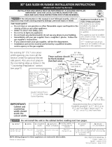
1 1/2" Max.
Shave Raised (3.8 cm Max.)
Edge to Clear
Space for a
311/2"min
(80 cm)
Wide
Cooktop.
See Dimension
C in table.
These surfaces should
be fiat & leveled
(hatched area)."-_
5" Min.
(12.7 em Min.)
From Wall Both Sides
30" Min.
(76.2 cm Min.)
13 vw
(see Note 3) 18" Min. (33 cm)
(45.7 cm) Min.
Locate Cabinet Doors
1" (2.5 cm) Min. from
Cutout Opening.
IMPORTANT: Cabinet and countertop
width should match the cutout width.
E
I
Do nat install the unit in the cabinet before reading next 2 pages.
35 7/8" (9].]cm) - 30" 31 1/2" 28 5/16" 30_+1/16"
36 5/8" (93cm) (76.2cm) (80cm) (71.9cm) (76.2-I-0.15cm)
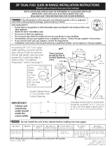
NOTE: Wiring diagram for these appliances are enclosed in this booklet.
Min.
(61 cm Min.)
Printed in Canada
21 3/4" (55.2cm) Min.
i 22 1/8" (56.2cm) Max 36 5/8" (93cm) Max.
24" (61cm) Min. with 35 7/8" (91.1cm)
backguard
P/N 318201693 (1010) Rev. A
English - pages 1-14
Espa_el - paginas 15-27
Wiring Diagrams - page 28

NOTES:
0
Do not pinch the power supply cord between the range and the wall.
Do not seal the range to the side cabinets.
24" (61 cm) minimum clearance between the cooktop and the bottom of the cabinet when the
bottom of wood or metal cabinet is protected by not less than 1/4" (0.64 cm) flame retardant
millboard covered with not less than No. 28 MSG sheet metal, 0.015" (0.4 mm) stainless steel,
0.024" (0.6 mm) aluminum, or 0.020" (0.5 mm) copper.
30" (76.2 cm) minimum clearance when the cabinet is unprotected.
For cutouts below 22 7/8"(58.1 cm), appliance will slightly show out of the cabinet.
Allow at least 20" (50.8 cm) clearance for door depth when it is open.
22 7/8" (58.1 cm) min.
23 1/4" (59.05 cm) max.
.__ 11/8"
(2.86 cm)
FRONT /
OF _ }::Ref. 1
CABINET
35 7/8" (91.1cm)
A
Side Panel
36 5/8" (93cm)
m
30"
(76.2cm)
31 I/2"
(80cm)
28 5/16" (71.9cm) 30___I/16"
(76,2+0,15crn)
21 3/4" (55.2cm) Min.
22 1/8" (56.2cm) Max
24" (61cm) Min. with
backguard
36 5/8" (93cm)
Max.
35 7/8" (91.1cm)

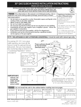
To avoid breakage: Do NOT handle or manipulate
the unit by the cooktop.
The counter-top around the cut-out should be fiat and leveled
(see hatched area on illustration 1).
Before installing the unit, measure the heights of the two (2)
cabinet sides (H1-4), front and back (see illustration 1) from
the floor to the top of the counter.
Level the range using
the leveling legs or
leveling device so that
the height from the floor
to the underside of the
cooktop frame is greater
than the tallest cabinet
measurement by at least
1/16" (see illustration 2).
Shave _
Raised
Edge
to Clear
Space for a
31 s/1J' (79.5 cm) I__
Wide Cooktop.
H1
Slide the unit into the cabinet. Make sure the center of
the unit is aligned with the center of the cabinet cut-out.
/
Illustration 1
The metal flange under each side of the cooktop MUST
be placed over the cabinet countertop for proper unit
support. The cooktop should NOT directly touch the
countertop (see illustration 2). Level the unit if needed.
After the installation, MAKE SURE that the
unit is supported by the leveling legs NOT
by the cooktop.
Illustration 2
j..."
To successfully
install the range,
the initial level
height from floor
to underside
of cooktop
frame should
be at least
1/16" taller than
cabinet sides
as measured in
step 1.
3

important Notes to the installer
1. Read all instructions contained in these
installation instructions before installing range.
2. Remove all packing material from the oven
compartments before connecting the gas and
electrical supply to the range.
3. Observe all governing codes and ordinances.
4. Be sure to leave these instructions with the
.
consumer.
Note: For operation at 2000 ft. elevations
above see level, appliance rating shall be
reduced by 4 percent for each additional
1000 ft.
important Nofe fo fhe Consumer
Keep these instructions with your Use & Care
Guide for future reference.
iMPORTANT SAFETY
iNSTRUCTiONS
Installation of this range must conform with
local codes or, in the absence of local codes,
with the National Fuel Gas Code ANSi Z223.1/
NFPA .54-latest edition.
This range has been design certified by CSA
International. As with any appliance using
gas and generating heat, there are certain
safety precautions you should follow. You will
find them in the Use and Care Guide, read it
carefully.
* Be sure your range is installed and grounded
properly by a qualified installer or service
technician.
* This range must be electrically grounded
in accordance with local codes or, in their
absence, with the National Electrical Code
ANSI/NEPA No. 70--latest edition. See
Grounding Instructions.
* Before installing the range in an area
covered with linoleum or any other synthetic
floor covering, make sure the floor covering
can withstand heat at least 90°F above
room temperature without shrinking,
warping or discoloring. Do not install the
range over carpeting unless you place an
insulating pad or sheet of 1/_" (10,16 cm) thick
plywood between the range and carpeting.
* Make sure the wall coverings around the
range can withstand the heat generated by
the range.
* Do not obstruct the flow of combustion air
at the oven vent nor around the base or
beneath the lower front panel of the range.
Avoid touching the vent openings or nearby
surfaces as they may become hot while the
oven is in operation. This range requires fresh
air for proper burner combustion.
Never leave children alone or
unattended in the area where an appliance
is in use. As children grow, teach them the
proper, safe use of all appliances. Never
leave the oven door open when the range is
unattended.
Stepping, leaning or sitting on the
doors or drawers of this range can result in
serious injuries and can also cause damage to
the range.
* Do not store items of interest to children in
the cabinets above the range. Children could
be seriously burned climbing on the range to
reach items.
* To eliminate the need to reach over the
surface burners, cabinet storage space
above the burners should be avoided.
* Adjust surface burner flame size so it does
not extend beyond the edge of the cooking
utensil. Excessive flame is hazardous.
* Do not use the oven as a storage space. This
creates a potentially hazardous situation.
* Never use your range for warming or
heating the room. Prolonged use of the
range without adequate ventilation can be
dangerous.
* Do not store or use gasoline or other
flammable vapors and liquids near this or
any other appliance. Explosions or fires could
result.
* In the event of an electrical power outage,
the surface burners can be lit manually. To
light a surface burner, hold a lit match to
the burner head and slowly turn the Surface
Control knob to LITE. Use caution when
lighting surface burners manually.
" Reset all controls to the "off" position after
using a programmable timing operation.
FOR MODELS WITH SELF-CLEAN FEATURE:
* Remove broiler pan, food and other utensils
before self-cleaning the oven. Wipe up
excess spillage. Follow the precleaning
instructions in the Use and Care Guide.
* Unlike the standard gas range, THIS
COOKTOP IS NOT REMOVABLE. Do not
attempt to remove the cooktop.

Before Starting
Tools you will need
For leveling legs and antl-tip brackets: _-._ _"_,_i-\,
• Adjustable wrench or channel lock pliers ......._s_ ....
• 5/16" Nutdriver or Flat Head Screw Driver
• Electric Drill & 1/8 Diameter _
Drill Bit (5/32" Masonry Drill
Bit if installing in concrete)
• Level & Measuring Tape
For gas supply connection:
• Pipe Wrench i_
• Brush
For burner flame adjustment:
• Phillips head _ and blade-type _o
screwdrivers
For gas conversion (LP/Propane or Natural):
• Open end wrench - 1/2" _
Additional materials you will need: _
• Gas line shut-off valve
• Pipe joint sealant that resists action of LP/_'---PfM_
Propane gas .............
• A new flexible metal appliance conduit
(_,,_"NPT x 3/4" or _,,_" I.D.) must be design
certified by CSA International. Because
solid pipe restricts moving the range we
recommend using a new flexible conduit
(4 feet length) for each new installation
and additional reinstallations.
• Always use the (2) new flare union
adapters _,'_" NPT x 3/4" or _,_" I.D.) supplied with the
new flexible appliance conduit for connection of the
range.
Cabinet Construction
_ To eliminate the risk of cabinet burns
and fire, do not have cabinet storage space above the
range. If there is cabinet storage space above range,
reduce risk by installing a range hood that projects
horizontally a minimum of 5" (12.7cm) beyond the
bottom of the cabinet.
| Cauntertop Preparation (figure 1)
° The cooktop sides of the range fit over the cutout
edge of your countertop.
° If you have a square finish [fiat) countertop, no
countertop preparation is required. Cooktop sides lay
directly on edge of countertop.
° Formed front-edged countertops must have molded
edge shaved fiat 3/4" (1.9 cm) from each front corner
of opening (Figure I).
° Tile countertops may need trim cut back 3/4"(1.9
cm) from each front corner and/or rounded edge
flattened [Figure 1).
3I_/2".._
(81 cm)
Formed or tile countertop trimmed
¾" (1.9 cm) back at front corners
of countertop opening.
Figure 1
If the existing cutout width is greater than
30-1/16" (76,4 cm), reduce the 3¼" (1.9 cm) dimension.
Countertop must be level. Place a level on the
countertop, first side to side, then front to back. If the
countertop is not level, the range wiii not be level.
The oven must be level for satisfactory baking results.
Cooktop sides of range fit over edges of countertop
opening.
Gas Entry Preparation
° The hatched areas are the locations where the gas
line can enter the cabinet [figure 2).
° The recommended position for the gas entry line is
located at 7" from the left cabinet wall and 2" from
the floor [figure 2).
° The shaded area is the location where the electric
outlet can be located [figure 2).
/
/
/
Recommended
position
\
Note: All dimensions are in inches (centimeter).
Figure 2
\ i
\
\
\
\
\
\
\\
\
',\
\
\
\
\
\
\

* If you are using a through the floor gas entry, remove
the line protector shield from the bottom of the unit to
allow access for the pipe line (figure 3).
e We recommend to install a pipe elbow right out of
the floor or wall towards the center of the unit to ease
the installation.
To remove the line protector, remove the 3 screws.
Figure 3
E! Provide an adequate Gas Supply
When shipped from the factory, this unit is designed
to operate on 4"(10,16 cm) water column (1.0 kPa)
Natural gas manifold pressure. A convertible pressure
regulator is connected to the range manifold and
MUST be connected in series with the gas supply line.
If LP/Propane conversion kit has been used, follow
instructions provided with the kit for converting the
pressure regulator to LP/Propane use.
Care must be taken during installation of range not to
obstruct the flow of combustion and ventilation ain
For proper operation, the maximum inlet pressure to
the regulator should be no more than 14"(35,56 cm) of
water column pressure (3.5 kPa). The inlet pressure to
the regulator must be at least 1" (.25 kPa) greater than
the regulator manifold pressure setting. Examples: If
regulator is set for natural gas 4"(10,16 cm) manifold
pressure, inlet pressure must be at least 5"(12.60 cm);
if regulator has been converted for LP/Propane gas
10"(25,4 cm) manifold pressure, inlet pressure must be
at least 11"(27_9 cm).
Leak testing of the appliance shall be conducted
according to the instructions in step 4.
The gas supply line should be 1/2" or 3¼" I.D. (Interior
Diameter)
| Connect the range to the gas supply
Important: Remove all packing material and literature
from range before connecting gas and electrical supply.
To prevent leaks, put pipe joint sealant on all external
pipe threads.
Your regulator is in location as shown in figure 2.
Do not allow regulator to rotate on
pipe when tightening fittings.
Connection to Pressure Regulator
The regulator is already installed on the appliance.
Do not make the connection too tight.
The regulator is die cast. Overtightening may crack the
regulator resulting in a gas leak and possible fire or
explosion.
Manual GAS FLOW Pressure
Shutoff Flare _'_ Flare Regulator
Valve Union Union ,_
on, '!i t t t
\_,. Nipple Flexible Nipple
Access
Off Connector
Cap
All connections must be wrench-tightened
Figure 4
Assemble the flexible connector from the gas supply
pipe to the pressure regulator in the following order:
1. manual shutoff valve (not included)
2. 1/2" nipple (not included)
3. 1/2" flare union adapter (not included)
4. flexible connector (not included)
5. 1/2" flare union adapter (not included)
6. 1/2" nipple (not included)
Z pressure regulator (included)
Use pipe-joint compound made for use with Natural
and LP/Propane gas to seal all gas connections. If
flexible connectors are used, be certain connectors are
not kinked.
The supply line must be equipped with an approved
manual shutoff: valve. This valve should be located in
the same room as the range and should be in a location
that allows ease of opening and closing. Do not block
access to the shutoff valve. The valve is for turning on or
shutting off gas to the appliance.
| Seal the openings
Seal any openings in the wall behind the range and
in the floor under the range after gas supply line is
installed.
Shutoff Valve =
Open position

Once regulator is in place, open the shutoff valve in the
gas supply line. Wait a few minutes for gas to move
through the gas line.
Check for leaks. After connecting the range to the gas
supply, check the system for leaks with a manometer.
If a manometer is not available, turn on the gas supply
and use a liquid leak detector (or soap and water) at
all joints and connections to check for leaks.
Do not use a flame to check for leaks
from gas connections. Checking for leaks with a flame
may result in a fire or explosion.
Tighten all connections as necessary to prevent gas
leakage in the range or supply line.
Disconnect this range and its individual manual
shutoff valve from the gas supply piping system during
any pressure testing of that system at test pressures
greater than 1/2 psig (3.5 kPa or 14" water column).
Isolate the range from the gas supply piping
system by dosing its individual manual shutoff valve
during any pressure testing of the gas supply piping
system at test pressures equal to or less than 1/2 psig
(3.5 kPa or 14" water column).
| LP/Propane Gas Conversion
This appliance can be used with Natural gas or LP/
Propane gas. It is shipped from the factory for use with
natural gas.
If you wish to convert your range for use with LP/
Propane gas, use the supplied fixed orifices located
in a bag containing the literature marked "FOR LP/
PROPANE GAS CONVERSION." Follow the instructions
packaged with the orifices for surface, oven and broil
burners conversion.
The conversion must be performed by a qualified
service technician in accordance with the
manufacturer's instructions and aii local codes and
requirements. Failure to follow these instructions
could result in serious injury or property damage.
The qualified agency performing this work assumes
responsibility for the conversion.
Failure to maize the appropriate
conversion can result in serious personal injury and
property damage.
| Electrical Requirements
120 volt, 60 Hertz, properly grounded dedicated circuit
protected by a 15 amp circuit breaker or time delay
fuse.
Note: Not recommended to be installed with a Ground
Fault Interrupt (GEl).
Do not use an extension cord with this range.
Grounding Instructions
IMPORTANT Please read carefully.
For personal safety, this appliance must be
properly grounded.
The power cord of this appliance is equipped with a
3-prong (grounding) plug which mates with a standard
3-prong grounding wall receptacle (see Figure 5) to
minimize the possibility of electric shock hazard from
the appliance.
The wall receptacle and circuit should be checked by
a qualified electrician to maize sure the receptacle is
properly grounded.
Where a standard 2-prong wail receptacle is installed,
it is the personal responsibility and obligation of the
consumer to have it replaced by a properly grounded
3-prong wail receptacle.
Do not, under any circumstances, cut or remove
the third (ground) prong from the power cord.
Disconnect electrical supply cord from
wail receptacle before servicing cooktop.
Preferred Method
Grounding type
wail receptacle
Do not, under any
circumstances, cut,
remove, or bypass
the grounding
prong.
Power supply cord with
3-prong grounding plug.
Figure 5
Moving the Appliance for
Servicing and Cleaning
Turn off the range line fuse or circuit breakers at the
main power source, and turn off the manual gas shut-off
valve. Maize sure the range is cold. Remove the service
drawer (warmer drawer on some models) and open the
oven door. Lift the range at the front and slide it out of
the cut-out opening without creating undue strain on the
flexible gas conduit. Maize sure not to pinch the flexible
gas conduit at the back of the range when replacing
the unit into the cut-out opening. Replace the drawer,
close the door and switch on the electrical power and
gas to the range.
7

Range installation
Important Note: Door removal is not a requirement for
installation of the range, but is an added convenience.
Refer to the Use
and Core Guide for
oven door removal
instructions.
Standard Installation
Figure 6
_]_The range cooktop overlaps the countertop at the
sides and the range rests on the floor. The cooktop
is 31 1/2" (81 cm) wide.
_lnstall base cabinets 30" (76.2 cm) apart. Make
sure they are plumb and level before attaching
cooktop. Shave raised countertop edge to clear 31
1/2" (81 cm) wide range top rim.
_lnstall cabinet doors 31" (78.7 cm) rain. apart so it
will not interfere with range door opening.
_]Cutout countertop exactly as shown on page 1.
For models equipped with Leveling Device:
|Make sure the front leveling legs and the rear
leveling device are setup higher than the height of
the cabinet.
__ Install the anfi-tlp bracket at this
point before placing the range at its final
position. Follow the installation instructions on
page 12 or 13 or on the anti-tip bracket template
supplied with the range.
_To provide an optimum installation, the top surface
of the countertop must be level and flat (lie on the
same plane) around the 3 sides that are adjacent
to range cooktop. Proper adjustments to make
the top flat should be made or gaps between the
countertop and the range cooktop may occur.
| [__1 To reduce the risk of damaging your
appliance, do not handle or manipulate it by the
cooktop or control console. Manipulate with care.
_Position range in front of the cabinet opening.
_Make sure that the cooktop which overhangs the
countertop dears the countertop. If necessary, raise
the unit by lowering the leveling legs.
_Slide the range into the cutout opening and center
it before leveling it.
|Level the range (see section 9). The floor where
the range is to be installed must be level. Follow
the instructions under "Leveling the Range- Models
Equipped with Leveling Device".
Adjust leveling legs so that the underside of the
cooktop is sitting on the countertop. Carefully
screw in (refer to Leveling the range: Models
equipped with Leveling Device") the back leveling
leg until the cool<top overhang touches slightly the
countertop. Then carefully screw in the front two
leveling legs until the cool<top overhang touches
slightly the countertop.
For models equipped with LevellncLLeLeg only (no
leveling device):
|Make sure the four leveling legs (front and rear) are
setup higher than the height of the cabinet (shown
on page 3).
| r_][__ Install the anti-tlp bracket at
this point before placing the range at its final
position. Follow the installation instructions on
page 12 or 13 or on the anti-tip bracket template
supplied with the range.
_To provide an optimum installation, the top surface
of the countertop must be level and flat (lie on the
same plane) around the 3 sides that are adjacent
to range cooktop. Proper adjustments to make
the top flat should be made or gaps between the
countertop and the range cooktop may occur.
| _][_!_i_e"_! To reduce the risk of damaging your
appliance, do not handle or manipulate it by the
cooktop. Manipulate with care.
_Position range in front of the cabinet opening.
_Make sure that the cooktop which overhangs the
countertop clears the countertop. If necessary, raise
the unit by lowering the leveling legs.
_Level the range (see section 9). The floor where
the range is to be installed must be level. Follow
the instructions under "Leveling the Range-Models
Equipped with Leveling Legs".
_Slide the range into the cutout opening.
lf Accessories Needed
Installatlon With Backguard
A backguard kit can be ordered through a Sears
Service Center. The cutout depth (213¼" (55,2cm) Min.,
221/8 '' (56,2cm) Max.) needs to be increased to 24"
(61cm) when installing a bad<guard
Installation With End Panel
An end panel kit can be ordered through a Sears
Service Center.
Installation With Side Panel
A side panels kit can be ordered through a Sears
Service Center. Install cabinet doors 31" (78,7cm) rain.
apart so as not to interfere with range door opening.

Leveling the Range
Models Equipped with Leveling Device
Level the range after installation in the cutout
opening.
1. Open the range drawer. The leveling screws control
the height of the rear leg.
2. Adjust the appliance legs as follows until the
underside of the cooktop (or cooktop glass) surface
is sitting level on the countertop (Figure 7).
a.To adjust the front legs_ use a wrench on the
leg base and turn counterclockwise to lower or
clockwise to raise the range.
b.To adjust the rear legs_ use a ratchet or
a nutdriver and turn the leveling screws
counterclockwise to lower or clockwise to raise
the range.
3. Check if the range is level by installing an oven rack
in the center of the oven and placing a level on the
rack (Figure 8).
4. Take 2 readings with the level placed diagonally in
one direction and then the other. Level the range° if
necessary_ by adjusting the leveling legs.
5. If the range cannot be level I contact a carpenter to
correct sagging or sloping floor.
Levellnl
Front
Leveffng
Leg
LOWER
RAISE
Figure 7
Models Equipped with Levelin_
Level the range and set cooktop height before
installation in the cut-out opening.
1. Install an oven rack in the center of the oven.
2. Place a level on the rack (see Figure 8). Take 2
readings with the level placed diagonally in one
direction and then the other. Level the range_ if
necessary_ by adjusting the 4 leg levelers with a
wrench (see Figure 18).
3. Taking care to not damage the countertop, slide
range into cutout opening and double check for
levelness. ........ ....
............. F*
@
i
J
i
1. Disconnect the power from the range.
2. Make sure the range is leveled.
3. Pull range toward you.
4. Measure the distance between the floor and the
surface underneath the cooktop frame.
5. Marl< that distance on the wall where the decorative
trim will be installed.
6. Draw a line.
Z Place the top of the decorative trim under that line.
8. Using the screws provided fix the decorative trim
into the wail.
9. Slide the range back into position as far as it will
go and reconnect the power source.
Trim
Figure 9
9

Check Operation
Refer to the Use and Care Guide packaged with the
range for operating instructions and for care and
cleaning of your range.
Remove all packaging from the oven before testing.
Install Burner Bases and Burner Caps
This range is equipped with sealed burners as
shown (see Figure 10).
a. Unpack burner bases and
burner caps.
b. Place burner bases over
each gas opening.
c. Make sure the burner
is properly aligned and
leveled. Place burner caps
over appropriate burner
bases.
NOTE: There are no burner
adjustments necessary on this
range.
Electrode
Figure 10
Turn on Electrical Power and Open Main
Shutoff Gas Valve
Check the igniters
Operation of electric igniters should be checked after
range and supply line connectors have been carefully
checked for leaks, and range has been connected to
electric power. To check for proper lighting:
a.Push in and turn a surface burner knob to the LITE
position. You will hear the igniter sparking.
b. The surface burner should light when gas is available
to the top burner. Each burner should light within four
(4) seconds after air has been purged from supply
lines. Visually check that burner has lit.
c. Once the burner lights, the control knob should be
rotated out of the LITE position.
There are separate ignition devices for each burner. Try
each knob separately until all burner valves have been
checked.
.
the slotted screw inside. Flame size can be increased
or decreased with the turn of the screw. Adjust
flame until you can quickly turn knob from HI to
LOWEST POSITION without extinguishing the flame.
Flame should be as small as possible and stable
without going out.
Repeat the steps from I to 4 until aii the burners
operate properi .
Hollow Valve
Stem
Figure 11
Adjust the "LOW" Setting of the Dual Valve
(Fig.12)
Note: On the dual valve the low setting of each portion
should be adjusted individually.
a. Push in and turn control to LITE until the rear portion
of the bridge burner ignites only.
b. Qulckly turn knob to LOWEST POSITION.
c. If burner goes out, reset control to OFF.
d. Remove the surface burner control knob.
e. The rear portion of the bridge burner flame size can
be increased or decreased with the turn of the screw
A. Use screw B to adjust the flame size of the center
portion of the bridge burner. Turn counterclockwise
the screw to increase flame size. Turn clockwise the
screw to decrease flame size. Adjust flame until
you can quickly turn knob from LITE to LOWEST
POSITION without extinguishing the flame. Flame
should be as small as possible without going out.
Note: Air mixture adjustment is not required on surface
burners.
Adjust the "LOW" Setting of Surface Burner
Valves (linear flaw and three position valves) (Fig 11)
Adjust "LO" setting as follows:
1. Let appliance cool down to room temperature.
2. Light up all burners by turning each control knob to
LITE until all burners ignite and set them at HI.
3. Quickly turn down the burner involved from HI to
LOWEST SETTING.
4. If burner goes out, readjust valve as follows:
Remove the burner control knob, insert a thin-blade
screwdriver into the hollow valve stem and engage
: \}
Figure 12
lo

Operation of Oven Burners and Oven
Adjustments
11.6.1 Electrlc ignition Burners
Operation of electric igniters should be checked after
range and supply line connectors have been carefully
checked for leaks, and range has been connected to
electric powen
The oven burner is equipped with an electric control system
as well as an electric oven burner ignJten If your model is
equipped with a waist-high broil burner igniter, it will also
have an electric burner igniter. These control systems require
no adjustment. When the oven is set to operate, current
will flow to the igniter. It will "glow" similar to a light bulb.
When the igniter has reached a temperature sumcient to
ignite gas, the electrically controlled oven valve will open
and flame will appear at the oven burner. There is a time
lapse from 30 to 60 seconds after thermostat is turned ON
before the flame appears at the oven burner. When the
oven reaches the display setting, the glowing igniter will go
off. The burner flame will go "out" in 20 to 30 seconds after
igniter goes "OFF". To maintain any given oven temperature,
this cycle will continue as long as the display is set to
operate.
After removing all packing materials and literature from
the oven:
a) Set the oven to BAKE at 300°F. See Use & Care Guide
for operating instructions.
b) Within 60 seconds the oven burner should ignite.
Check for proper flame, and allow the burner to cycle
once. Reset controls to off.
c) If your model is equipped with a high-waist broiler,
set oven to broil. See Use & Care Guide for operating
instructions.
d) Within 60 seconds the broil burner should ignite. Check
for proper flame. Reset controls to off.
k!wer _
Oven Baffle
(remivable
Figure 13
//
Waist-High Burner
_.5._._Ai r Shutter
Lower Oven Bottom
_;_-"Ai r Shutter (removable)
screws at rear of oven bottom. Pull up at rear, disengage
front of oven bottom from oven front frame, and pull the
oven bottom out of the oven. Remove burner baffle so that
burner flame can be observed.
If the flame is yellow, increase air shutter opening size (see
"2" in Figure 14). If the entire flame is blue, reduce the air
shutter opening size.
To adjust frame loosen loci< screw (see "3" in Figure 14),
reposition air shutter, anc_fi ._nloci< screw. Replace
oven bottom. Burner Tube
Lock Screw
Air Shutter
tOrifice Hood
Figure 14
11.6.3 Air Shutter=Broil Burner
The approximate flame length of the burner is 1 inch
(distinct inner cone of blue flame). To determine if the
broil burner flame is proper, set the oven to broil. If
flame is yellow, increase air shutter opening size (see "2"
in Figure 14 ). If the entire flame is blue, reduce the air
shutter opening size. To adjush loosen lock screw (see "3"
in Figure 14), reposition air shutter, and tighten lock screw.
When All Hookups are Complete
Make sure all controls are left in the OFF position.
Make sure the flow of combustion and ventilation air to
the range is unobstructed.
Model and Serlal Number Location
The serial plate is located on the oven front frame
behind the oven door (some models) or on the drawer
side frame (some models).
When ordering parts for or making inquiries about your
range, always be sure to include the model and serial
numbers and a lot number or letter from the serial plate
on your range.
Your serial plate also tells you the rating of the burners,
the type of fuel and the pressure the range was
adjusted for when it left the factory.
11.6.2 Air Shutter=Oven Burner
The approximate oven burner flame length is 1 inch
(distinct inner cone of blue flame).
To determine if the oven burner flame is proper, remove
the oven bottom and burner baffle and set the oven to
bake at 300°1:.
To remove the oven bottom, remove oven hold down
Before You Call for Service
Read the Before You Call Checklist and operating
instructions in your Use and Care Guide. It may save
you time and expense. The list includes common
occurrences that are not the result of defective
workmanship or materials in this appliance.
Refer to your Use & Care Guide for Sears service phone
numbers or call 1-800-4-MY-HOME®.
11

Anti-Tip Brackets Installation
Instructions
| Models Equipped with Leveling Device
To reduce the risk of tipping of the range,
the range must be secured to the floor by properly
installed anti-tip bracket and screws packed with the
range. These parts are located in the oven. Failure to
install the anti-tip bracket will allow the range to tip over
if excessive weight is placed on an open door or if a child
climbs upon it. Serious injury might result from spilled hot
liquids or from the range itself.
Follow the instructions below to install the anti-tip
brackets.
If range is ever moved to a different location, the anti-
tip brackets must also be moved and installed with the
range.
Tools Required:
Adjustable Wrench
Ratchet
Drill & 1/8"(0,32 cm) bit
5/16" (0,8 cm) Nutdriver
Level
The anti-tip bracket attaches to the floor at the back of
the range to prevent range from tipping. When fastening
bracket to the floor, be sure that screws do not penetrate
electrical wiring or plumbing. The screws provided will
work in either wood or concrete.
1. Draw a center line (CL) on the floor where the range
should be installed. Also draw a line on the floor at
the range back position if there is no wall.
(CL : Center line)
Door
Cabinet
2. Unfold paper template and place it fiat on the floor
with the right rear corner positioned exactly on the
intersection of the center and back lines you just drew
before. (Use the diagram below to locate brackets if
template is not available (Figure 15)).
3. Mark on the floor the location of the 4 mounting
holes shown on the template. For easier installation,
3/16"(0,48 cm) diameter pilot holes 1/2"(1,27 cm)
deep can be drilled into the floor.
4. Remove template and place bracket on floor. Line up
holes in bracket with marks on floor and attach with
4 screws provided. Bracket must be secured to solid
floor (Figure 15). If attaching to concrete floor, first
drill 3/16"(0,48 cm) dia. pilot holes using masonry drill
bit.
5. Be sure the 4 leveling legs are at the highest position
they can be.
6. Slide range into place making sure structure of the
range is trapped by the anti-tip bracket (Figure 15).
Lower the range by adjusting the 4 leveling legs until
the underside of the cooktop is sitting level on the
countertop. Refer to "Leveling the Range" section.
7. After installation, verify that the anti-tip bracket is
engaged by grasping the top rear edge of the range
and carefully attempt to tilt it forward to make sure
range is properly anchored.
H
Floor Me
Screws
Figure 16
_LIDE
BACK
Figure 15
12

| Models Equipped with Leveling iec_
To reduce the risk of tipping of the range,
the range must be secured to the floor by properly
installed anti-tip brackets and screws packed with the
range. These parts are located in a plastic bag in the
oven. Failure to install the anti-tip brackets wiii allow
the range to tip over if excessive weight is placed on
an open door or if a child climbs upon it. Serious injury
might result from spilled hot liquids or from the range
itself.
Follow the instructions below to install the anti-tip
brackets.
If range is ever moved to a different location, the anti-
tip brackets must also be moved and installed with the
range. To check for proper installation, see step 5.
Tools Required:
5/16" (0,79 cm) Nutdriver or Flat Head Screwdriver
Adjustable Wrench
Electric Drill
3/16"(0,5 cm) Diameter Drill Bit
3/16"(0,5 cm) Diameter Masonry Drill Bit (if installing in
concrete)
Brackets attach to the floor at the back of the range to
hold both rear leg levelers. When fastening to the floor,
be sure that screws do not penetrate electrical wiring or
plumbing. The screws provided will work in either wood
or concrete.
ij Anti-Tip Bracket
Back Edge of
Range or Rear Wall _ .
i _-_,(23.2 _1 • (46.4_m)
Anti-Tip _ _ '_ 28 1/8"
_--. _..(71.4 cm)
Bracket "'. (Rear width of range
with body sides)
(CL = Cen|er llne)
i
Figure 17
Slide Back
1. Unfold paper template and place it flat on the floor
with the back and side edges positioned exactly
where the back and sides of range will be located
when installed. (Use the diagram below to locate
brackets if template is not available. (Figure 17))
2. Mark on the floor the location of the 4 mounting
holes shown on the template. For easier installation,
3/16" (0.5 cm) diameter pilot holes 1/2" (1.3 cm)
deep can be drilled into the floor.
3. Remove template and place brackets on floor
with turned up flange to the front. Line up holes
in brackets with marks on floor and attach with 4
screws provided. Brackets must be secured to solid
floor. If attaching to concrete floor, first drill 3/16"
(0.5 cm) dia. pilot holes using a masonry drill bit.
4. Level range if necessary, by adjusting 4 leg levelers
with wrench (Figure 18). A minimum clearance of
1/8" (0.8 cm) is required between the bottom of the
range and the rear leg levelers to allow room for
the anti-tip brackets.
5. Slide range into place making sure rear legs are
trapped by ends of brackets. Range may need to
be shifted slightly to one side as it is being pushed
back to allow rear legs to slide under brackets. You
may also grasp the top rear edge of the range and
carefully attempt to flit it forward to make sure
range is properly anchored.
/
/
/
/
/
<
Leveling Leg
Raise "-.
Lower
Figure 18
13

[]
W-6
• W-14
C2
OVEN CIRCUIT//CIRCUITO DE HORNO//CIRCUIT FOUR
OONVRCI]ON MOTOR FAN/
VENTILADOR DEL ,VOTORCONVECCION/
_OTEUR VENTILATEUR CONVECTION
oR,w.s <¢_ BR_!__ 0,0..... , i
W- 19 LATCH \MOTOR/NOTOBxf_i_ _,CERROUO/MOTEUR VEBROU il
LAMP HALOGEN,LANPARA HALOGENE/LUMIERE HALOGENE OR/O/OU
OVEN LAMP/LANPARA GEL HORNO/LANPE DE FOUR 1
.... I BR/W-1 :
LAMP HALOGEN/LAMPARA BALOGENE/LUMIERE RALOGENE OR/GiGS I
OVEN LAMP/LAMPARA DEL BORNOJLAMPE DE FOUR GY 19 1
BK19
FAN MOTOR/_OTOS DE VENTELADOR/MOTEUR VENTILATEUP /
W - 1 4 S_ i _'
.............. d_' _ BK-14 013 BK-19 BK-19
\/
CONVECTION ELENENT/ELEMENTO DE CONVECCIOR/ELEMENT CONVECTION
0-5 C_ C 0-5 07 0-1 I
BAKE IGNITER/
i
IELECTRONZC OVEN CONTROL/
I,CONTROL DE HORNO ELECTRONZCO/
ICONTROLE ELECTRONIQUE FOUR
IES 5XX
THERMOSTAT/
TERMOSTATO/
THERMOSTAT
8
7
6
5
4
3
2
1
J3
BANE VALVE/
VALVULA DE HORNEAR/
OPTIONAL BROIL VALVE/ BROIL tGNITER/
OPCIONAL VALVULA DE ASAR/ ENCENBIDO DE ASAR/
WARNER El EMRNT [
ELENENTO DE CALENTADOR
R/W-t9 C1 R/W-14
R-2 R-6
C16 .......
C12 R-6
R-6
L J ,
Pll
V-19 V-14
] ............. C3
TEMPERATURE PROBE/
SORDA DE TENPERATURA/
SONDE THERMIGUE
V-19
] BL/W-19 BL/W-14
09
O00B SWlrOBI 1
TNTERRUPTOR DE PUERTA/
ZNTERPUPTEUR PORTE
BK/W-19
[] : cs _" oK/w-_4
_] i /OH,, /iOPBIONAL,..... i
FACULTATIF
[ LO LENIT THER}_OSTAT/
TERMOGTATO DE LIMITO LO/
THERMOSTAT BARGE []BITE
A1 A3 '
[ MOTOR SWITCH lATCH/ [ ,
I INIBRRUPIOR ROTOR DE LOQUE_A lie PUERTA/ [
', INTERRUPTEUR NOTEUR VERROU I
[] ! 0/W-19 CI1 £[_{:!4 c_""I> 0/W-14 I
NO C
CONNECTOR/ CONNECTOR/
CONECTOR/ CONEGTOR/
GOHNEGTEUR CONNECTEUR
O C
COOKTOP CIRCUIT// CIRCUITO DE PLANCHA DE COCINAR // CIRCUIT TABLE CUISSON CONNECTOR/ CONNECTOR/
CONECTOR/ CONECTOR/
OONNEC1EUR CONNECTEUR
RIGHT REAR IGNITER SWITCH/ W_23 _'__ B i A
. INTERRUPTOR ENCENDIDO ................. ..............................................' r.............. i
"_ _ 'RAS_R_ DE_ AHO[ , 1 23 1 2 3 4if, .G ,, ,-_ _.) ,. ©, _.,\>
P UBUR TOP BUPNE '.2 _.}
ARRIERE BROIT QUEMADOR DE ENCENBIDO SUPERIOR/ , I
4 BOOGIE D'ALLUMAGE BRULEUR
N R 14 R 1
RIGHT FRONT IGNITER SWITCH/ IGNITER MODULE BOARD/ CO[ORS/CODIGOG DE CO[ORES/CODE DOU[EUR
W÷5 , [NTERRUPTOR ENCBNDIDO CUARDO DE MODULO DE cNCENDIDO/ -.
IL2 D_N_OLMEUR _oEEOHNEOTIONA,,U_UR............................_.GLAO*/NEGRG/NO_R
LU G. -GREEN/VERDE/VERT
........./RLANRG,O,A°O
R-14 R-14 / OPCiONAI _"" GUEMADOP DE PNOENOEO0 SUPPRIOR/ R,-RED/ROJO/ROUGE
FACUL1A IF BOUGIE D'ALLUMAGE BRULEUR O. ORANGE/NARANUA/ORANGB
J • Y. -YELLOWIAMARZLLO/JAUNE
C_I\_ R JGN£_ R SW IOH ;: ::::::::::::::::::: BR _BROWN/CAF[ /BNUR
' , INTeR[UP OR NCEN/]II]O [ ; W23 ¢.... B[. -B[ UB/AZUI /B EU
POWER CORD/ [ BE CE TPB_ ' } [ 4 }
PARA TRANSPORTE I V _ _ INrEPRUPrEUR ALLU_.EUR _ _ _ _ / ..... _ t ; ' CODE GAUGE TEBP.'C CSA UL
....' > :(i<11:o.,,..., o°.o.......
CABLE R ]_zl R_14 e_ " G)_&_ADO_ }E ENCENDIDO GUP_"R OR/ [ CODE SAI IBRE
D ALIN_ERTATIOB
LEFT FRONT IGNITER SWITC_ / BOJRIE D'ALLHBAGE BRULEUR j I 18 t2B CL12BI 3t13
/ i] NTERRUPTOR ENCENDIBO
<_-,-_-z_E.......... 0 <',J"-" /......... , 2 ...............
(_-- , RENIE £ZQDlcRG / OPDJONA [ 3 14 t25 CL1251 3173
_ _ 'INTEGRUPTPUR A _UMRUR _ ,/_.AGu............_ W 2- [_-1 4 12 12S O_ 12Sl 3173
........... ,_ ._ _ s ,s 1Bo .....s03_21
_ r,, .... so E×_lSO3G21
LEFT REAR IGNITER Sf_IITCH/ TOP BURNER/_ [
TRANSFORMER/ I -" ZRTERRUPTOR ENCENDIDO [ QUEGADOP DE ENCENDEO0 SUPERIOR/ i G 12 150 EXL-150 3321
TRANSPORMADOR/ TRASERO [ZQUIERDO/ BOUGZE D'ALLUMAGE BRULEUR 9 10 150 EXL-I50 3321
O1 O3 TRANSPOR#ATEUR _/ ZNTEPPUPTPUR AL_U_EUR 10 18 200 SEW1 3t22
R 14 ARPIEPE GAUCHE 11 16 200 SEW 1 3122
120VAC 120VAC - R-14 W-23 12 12 250 3252
...... T_ _ 3 _\ [ TOP BURNEP/_ _ ,.', 14 20 150 EXL*150 3321
2_ _5 W-14 QUEMADOP DE ENCENDIBO SUPERIOR 1S 8 i50 EXL 150 3321
D2_ ................................................................ BOUGZE D'ALLUMAGE BRULEUR 16 8 60
17 10 60
CAUTIONIDZSCONNECT POWER BEFORE SERVICING UNIT. 18 10 200 SEW*I 3t22
LABEL ALL WIRES PRIOR TO DISCONNECTION WHEN SERVICING CONTROLS. 19 20 t25 CL1251 3t73
WIRINGS ERRORS CAN CAUSE _MPROPER AND DANGEROUS OPERATION, 20 20 200 SEW 1 3t22
VERIFY PROPER ORERATEON AFTER SERVICING. 21 22 t25 3266
ATENCION:CORTAR LA CORRIENTE ANTES DE REALIZAR EL I,?ANTENIMIENTO #EL ELECTRODOMESTICO. 22 22 t50 10109
RT_QUETE TODOS OS CABLES ANTES DE DESCORECTAR CUANDO NASA EL SERVIC[O A LOS CORTROLES. 23 18 200 3573
EPPORES AL VOLVER A ENSAMBLAR LOS CABLES PUEOE CAUSAR PALLAS U OPERACIONES PELZGROSAS,
VERIFIQUG LA CORRECTA OPERASION DESPUES DEL SERV;[CIO.
ATTENTIONtOOUPEZ L'AL]MENTATZON AVANT D'EFFECTUER LA REPARATION.
IDENTIPIEZ TOUR LEG PILS AVANT DE LES DEBRANCHER QUANB L'APPAREIL EST HOBS SERVICE.
LEG ERREURS DE CONNECTION DE FILG PEUVENT CAUSER UN MAL FONETIONNE_ENT ETUN DANGER D USAGE DE L'APPAREIL,
VERfFIEZ [E BON FONGI[ONNENENT RE L'APPAREII APRES LE SERVICE.
28
/