Page is loading ...

U
ltra Elite®
XT Communications
System
Voice Amplifier/Radio Interface
CLEANING AND MAINTENANCE
The Ultra Elite XT Communications System should be cleaned and disinfected
after each use. Follow an established cleaning and disinfecting program. Failure
to follow this procedure can damage the Ultra Elite XT Communications System.
Remove the Amplifier from the Apparatus
1. Unscrew the thumbscrew and disconnect the amplifier.
2. Close the dust cover on the (two pin) connector.
Cleaning and Disinfecting
1. Prepare a cleaning solution by adding Confidence Plus® Cleaning Solution
(P/N 10009971) to water, following the instructions on the Confidence Plus
container.
NOTE: Prior to cleaning the unit, verify that the battery door on the amplifier is
fully closed and secure with the thumb screw.
Although the system is water resistant, never submerge the Ultra Elite XT
Communications System modules in water or any other liquid.
2
. Clean by wiping with a damp sponge or cloth containing Confidence Plus
from MSA. Follow the directions on the Confidence Plus container for
mixing directions and recommended times.
Communications System Inspection
1. Inspect the Ultra Elite XT Communications System modules. Look for
cracks or other signs of damage which could allow contaminants to enter
the module housings.
2. Reassemble the amplifier module on the Ultra Elite Facepiece.
3. Check out the system functions.
a. Momentarily depress the on/off button on the Ultra Elite XT
Communications System unit and then release it.
b. The red LED should be illuminated at the top of the amplifier unit.
c. Scrape your fingernail lightly across the voicemitter microphone grille
of the voicemitter microphone assembly. You should hear this sound
reproduced in the amplifier speaker.
d. Depress, hold for 3 seconds, then release the on/off button again to turn
the unit OFF. The LED indicator on the amplifier unit will also turn OFF.
Facepiece Inspection (perform monthly)
1. Inspect the facepiece rubber behind the bracket for holes or tears.
NOTE: The mounting bracket must be removed from the facepiece. Refer to P/N
10022713 for installation information.
Storage
To store the Ultra Elite XT Communications System components, be sure that
unit is OFF (red LED is not illuminated). For prolonged storage, remove the
batteries to prevent battery corrosion. Store the units in a cool, dry place.
Installing the Batteries
In continuous service, battery life will vary depending on user conditions. The
battery is not rechargeable.
Use only 1.5 Volt Duracell MN2400 or Rayovac AAA alkaline batteries. Use
of other batteries, or a combination of batteries from different
manufacturers, will affect performance of the unit and will void the
intrinsic safety approval. Misuse can result in serious personal injury or
death.
1. Loosen the thumbscrew to open battery door.
2. Ensure that the battery compartment is free of moisture or debris.
3. Insert three (3) AAA batteries according to the battery orientation noted
next to the compartment door.
4. Close the battery door and tighten the thumbscrew.
Battery Disposal/Recycling
Dispose of or recycle batteries in accordance with all applicable federal, state,
and local regulations.
DO NOT dispose of the battery in fire. It may explode. Failure to follow this
warning can result in serious personal injury or death.
To reduce the risk of explosion do not mix old batteries with used
batteries or mix batteries from different manufacturers.
W
ARNING To reduce the risk of ignition of a flammable or explosive
atmosphere, batteries must be changed only in a location known to be
non-hazardous.
TROUBLESHOOTING
Ear Speaker Not Receiving
• Verify that radios communicate with each other with no accessories
attached.
• Verify that all connectors are fully engaged.
• Adjust receiving radio volume.
• Position ear speaker near ear by bending flexible boom.
Radio Not Transmitting
• Verify that radios communicate with each other with no accessories
attached.
• Verify that all connectors are fully engaged.
• Adjust receiving radio volume.
Garbled or Unclear Communications
• Verify that radios communicate with each other when no accessories
attached.
• Verify that all connectors are fully engaged.
• Adjust receiving radio volume. Some radios will produce distorted sound at
full volume.
• Adjust position of ear speaker by bending flexible boom.
DO NOT attempt any repairs beyond those specified in the Troubleshooting
Table; otherwise, serious injury or death could result. Only trained
personnel, authorized by MSA, are permitted to maintain this
Communications System.
Replacement Parts and User’s Instructions
Item Part Number
1. Amplifier Kit . . . . . . . . . . . . . . . . . . . . . . . . . . . . . . . . . . .10144672
2. Amplifier RI Kit . . . . . . . . . . . . . . . . . . . . . . . . . . . . . . . . .10144675
3. Bracket and Voicemitter Kit . . . . . . . . . . . . . . . . . . . . . . . .10023055
4. Bracket and Voicemitter Installation Instructions . . . . . . . .10022713
5. Two Screws to Connect Microphone Wire
to the Mounting Bracket . . . . . . . . . . . . . . . . . . . . . .10034748-SP2
6. Dust Cover, Screw, & Washer for
Microphone Wire Connection . . . . . . . . . . . . . . . . . . . . . .10025123
7. Mounting Bracket Sub-assembly with
Dust Dust Cover Attached . . . . . . . . . . . . . . . . . . . . . . . . .10024077
8. Voicemitter with Gasket Attached Wire & Connection . . . .10024076
9. Retaining Ring for Voicemitter . . . . . . . . . . . . . . . . . . . . . .10023505
10. Cable Clip (with Longer Screw) for RI Pigtail . . . . . . . . . . .10024075
11. Amplifier Kit (#1) with Bracket and Voicemitter Kit (#3) . . .10144673
12. Amplifier RI Kit (#2) with Bracket and Voicemitter Kit (#3) .10144676
13. O-ring for Mic. Connector . . . . . . . . . . . . . . . . . . . . . . . . .10025124
14. Lapel Microphone Installation and Operation Instructions .10055138
15. Basic PTT Install and Operation Instructions . . . . . . . . . . .10056230
Lapel Microphone and Basic PTT Microphone Kits for Radio Interface.
(Contact MSA Customer Service if specific radio is not listed below)
Operating and Maintenance Instructions
TAL 149 (L) Rev. 3 © 2014 Prnt. Spec. 10000005196(W) Mat. 10128860
D
oc. 10128860
Read this manual carefully if you have, or will have, the responsibility for using or
servicing the product. The Ultra Elite XT Communication System from MSA will
perform as designed only if used and serviced according to the instructions.
Otherwise, the product could fail to perform as designed and persons who rely on
this product could sustain serious personal injury or death.
CAUTION
A
mplifier Kit P/N 10144672
Amplifier and Bracket Kits P/N 10144673
Amplifier RI Kit P/N 10144675
A
mplifier RI and Bracket Kits P/N 10144676
The warranties made by MSA with respect to the product are voided if the
product is not installed, used, and serviced in accordance with the instructions
in this manual. Please protect yourself and your employees by following the
instructions. Please read and observe the WARNINGS and CAUTIONS inside. For
any additional information relative to use or repair, write or call 1-877-MSAFIRE
during regular working hours.
This product is NIOSH certified as an accessory for the Ultra Elite XT Facepiece
for use with FireHawk M7XT and FireHawk M7 Air Masks. The Ultra Elite XT
Communications System is NOT approved for use with other MSA MMR
breathing apparatus using previous Ultra Elite Facepiece versions. Only the
Amplifier and Amplifier Radio Interface are approved by NIOSH for use in a
CBRN application when used in an approved configuration. This product is
certified compliant to the NFPA 1981-2007 and 2013 editions.
SPECIAL OR CRITICAL USER’S INSTRUCTIONS
1. Do not alter this unit. You will void the intrinsic-safety rating, and may
affect the intrinsic-safety of the device.
2. Evaluate this unit, and any radio transceiver with which it may be used,
before entering a hazardous atmosphere. Be certain that this unit is not
affected adversely by radio frequency energy.
3. Evaluate this unit, and any radio transceiver with which it may be used, as
a source of radio frequency interference to other apparatus before entering
a hazardous atmosphere.
4. Misuse or abuse of the Ultra Elite XT Communications System, or the
equipment to which it is attached, or using this equipment in a manner or
situation not intended by the manufacturers, may result in damage to the
Ultra Elite XT Amplifier / Radio Interface, or equipment connected to the
Ultra Elite XT Communications System, or may result in personal injury or
death to the user or persons dependent on the user.
WARNING
WARNING
WARNING
WARNING
W
ARNING
P/N 10144672
P/N 10144675
1
678
For More Information, call 1-800-MSA-2222 or Visit Our Website at www.MSAsafety.com
CAUTION
Lapel Mic and PTT Part Numbers
B
rand
R
adio Model
L
M
P
TT
G
E Ericsson
Jaguar 700P / 700PI, P700IP / 7150 /
7170, HT-7150S / 7170T, HA8VSX
1
0068237
1
0070362
K
enwood
TK-190 / 280 / 290 / 290K / 380 /
390 / 480 / 481 / 2140 / 2180 / 3140 /
3
180 / 5210 / 5220, NX200 / 300 /
3
00K
10042941 10045710
T
K-208 / 220 / 240 / 248 / 250 / 260 /
2
70 / 270G / 272 / 308 / 320 / 340 /
350 / 353 / 360 / 370 / 372 / 373G /
430 / 2100-K2 / 2160 / 2170 / 2200 /
2
202 / 2302 / 2312 / 3101K / 3160 /
3
170 / 3173 / 3200 / 3202 / 3212 /
3360, TH-21 / 25A / 41 / 45 / 75 /
91A / 2102 / 3102
1
0042939
1
0045708
M
otorola
GP-900, HT-1000, JEDI, JT-1000,
MT-1500 / 2000, MTS-2000, MTX,
M
TX-838 / 839 / 2000 / 8000 / 9000
T
ranscrypt Stealth, PR1500,
P
TX-1200 / 3600, XTS-1500 / 2500 /
3000 / 3500 / 5000 / 5000R
10042903 10045662
A
PX-6000 / 7000, DGP-6150+,
XPR-6500 / 6550 / 6580
1
0092733
1
0108643
G
P-328 / 329 / 338 / 339 / 340 /
360 / 680, HT-750 / 1250 / 1550 /
1
550-XLS, MTX-850 / 850-LS / 950 /
8
250 / 8250-LS / 9250, PR-860,
P
RO 5150 / 7150 / 7350 / 7550 /
9150, PTX-700 / 760 / 780
10042922 10045691

5. Always inspect the Ultra Elite XT Communications System for damage
before use. If damage is found, tag the unit and immediately remove the
device from service. NEVER USE A DAMAGED OR NON-FUNCTIONAL
COMMUNICATION SYSTEM!
STANDARD USE OF PRODUCT
1. Clean / disinfect, if needed and Inspect (See CLEANING AND
M
AINTENANCE)
2. Don facepiece with installed amplifier
3. Turn on amplifier when communications are required.
4. Turn off amplifier when operations are completed
5. Doff facepiece
Helpful Hint to Avoid Feedback:
Amplifier feedback occurs when the facepiece diaphragm microphone picks up
its own sound projected from the speaker and loops that sound back into the
system, causing a loud screech. To prevent feedback, avoid leaving the
amplifier in the "on" mode when the facepiece is not donned to the face, and
avoid placing any surface (including one's hand) directly over the speaker. If
feedback occurs:
* turn the amplifier off if the facepiece is not donned to the face
* remove the obstruction from the speaker (feedback should immediately cut
out)
DESCRIPTION
The Ultra Elite XT Communications System Amplifier Radio Interface (RI) Version
allows a user to communicate clearly and easily, both face-to-face and over a
hand-held radio, while wearing an SCBA equipped with an Ultra Elite Facepiece.
The system consists of three main components that attach to the user’s radio:
• An internal microphone assembly
• An Amplifier or Amplifier RI hooked to the facepiece with a mounting
bracket. The Amplifier RI (Radio Interface) includes an ear speaker and a
cable to connect to a Lapel Microphone or Push-To-Talk.
• A Lapel Microphone or optional Basic PTT with specific radio interface
connection.
NOTE: To complete the system, the user must select and purchase the proper
Lapel Microphone or Basic PTT that fits his/her specific radio. (see Table in Parts
List)
When the Amplifier RI Assembly is connected to the Lapel Microphone,
communication is the same as with the Basic PTT.
The Lapel Microphone can be used without the Amplifier RI. The Lapel
Microphone interface contains a remote speaker and microphone with a Push-
To-Talk Button. This unit allows remote, shoulder mounted, radio transmission
and reception.
When the Amplifier RI is connected to the Basic PTT, the user presses the button
to transmit. Incoming radio messages are heard at the Amplifier RI ear speaker.
The Lapel Microphone is equipped with the following:
• Female connection for the male connector of the Amplifier Radio Interface
cable.
• Belt clip on the back of the Lapel Microphoe for attaching the Lapel
Microphone to the user’s clothing.
• Microphone, speaker, and a Push-To-Talk Button.
• The Push-To-Talk Button is protected against inadvertent operation by a
guard. The unit is shipped with the taller guard installed. When the taller
guard is removed, the Push-To-Talk Button becomes fully exposed and
easier to access. The shorter guard is included and available for
replacement.
• Cable and radio-specific connector.
The amplifier operates from three standard AAA alkaline batteries and notifies
the user when the batteries need to be replaced. Each Amplifier and Amplifier RI
has a visual LED low battery indicator.
Intrinsically-Safe Rating
The Ultra Elite XT Communications System is certified Intrinsically-Safe in the
United States for use in Class 1, Division 1, Groups C, D, E, F, and G hazardous
locations (UL 913 6th Edition and ANSI/UL 913-2011 7th Edition).
The Ultra Elite XT Communications System is certified intrinsicallysafe in
Canada CAN CSA-C22-2-No.25, 157.
NOTE: The intrinsically-safe level of any system which uses the Ultra Elite XT
Communications System is that of the lowest intrinsically-safe rating of any
single component in the system.
A copy of the Control Drawing may be obtained by contacting MSA’s Customer
Service Department directly:
Phone: 1-877-MSA-FIRE
Fax: 1-877-672-3930
Email: info@msasafety.com
Mail: Attn: Customer Service
Mine Safety Appliances Company
1000 Cranberry Woods Drive
Cranberry Township, PA 16066 USA
Ensure each component of the intrinsically safe system is suitable for the
H
azardous (Classified) Location prior to entering.
SUBSTITUTION OF COMPONENTS MAY IMPAIR INTRINSIC SAFETY.
Ensure the radio used is intrinsically safe before entering a hazardous
atmosphere. Misuse can result in serious personal injury or death.
The Ultra Elite XT Communications System must be tested before entering
a hazardous atmosphere. If the Ultra Elite XT Communications System
fails to operate as designed, disconnect at the radio and use the radio
independently from the communication system.
PREPARING FOR USE
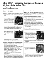
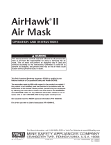
Attachment of Amplifier or Amplifier RI to Bracket
1. Ensure dust cover is open on mounting bracket (two pin) connector.
2. To attach the amplifier onto the bracket with the hook at the front of the
amplifier. The amplifier can be attached or removed from the facepiece in
seconds without tools.
a. Align the amplifier so the connector
is correctly in position.
b. Press the amplifier into place on the
bracket and tighten thumbscrew on
back side of mounting bracket.
3. If not using radio, wrap the cable around the lens ring and connect the
cable to the clip on the right side.
DONNING THE UNIT
Always test the Ultra Elite XT Communications System for damage and be
sure it operates properly before entering any hazardous atmosphere. Do
not use this device unless it passes all inspection and operational tests.
Failure to follow this warning can result in serious personal injury or
death.
Ensure the radio is at the lowest volume setting. Control the volume for
the Microphone and Ear Speaker Assembly or Lapel Microphone with the
volume control on the radio.
Amplifier
1. Don the SCBA Ultra Elite Facepiece following the instructions supplied with
the SCBA.
2. Turn the Voice Amplifier ON:
a. Momentarily depress the on/off button on the amplifier and then release
it.
b. A small, red LED should be illuminated at the top of the amplifier
housing. If the LED is flashing, the battery is low and must be replaced
before you use the amplifier. If the light does not illuminate, verify that
the unit contains fully-charged batteries. If it does and the light
continues to remain off, label the unit as nonfunctioning and take the
unit out of service until it can be repaired.
c. For amplifier operation the unit must be ON. All facepiece audio is
reproduced at the amplifier.
NOTE: The amplifier remains ON until you press and release the button, or until
approximately 60 minutes have passed since last use. Always be sure to turn
the unit OFF (red LED should not be illuminated) before storing the facepiece.
3. Speak into the facepiece in a normal voice. Your voice is projected from the
amplifier speaker.
NOTE: The amplifier is equipped with an 'auto-off' feature which will
automatically shut down the unit after approximately 60 minutes since last use
to avoid premature battery depletion. However, if the unit is in a noisy
environment, it may continue detect sound as though it is in use. In this case,
the unit will continue to operate until it is either shut off, the batteries deplete,
or the it remains in a quiet environment long enough for the auto-off feature to
engage. Always be sure to shut the unit OFF when not in use.
Amplifier RI
Read the Amplifier Procedure in the Donning the Unit section.
Be sure to observe all CAUTIONS, WARNINGS, and NOTES. Before donning the
facepiece, check that the radio interface connector is attached to your radio
before use.
NOTE: The radio interface must be used with the Voice Amplifier RI on/off button
turned ON.
Amplifier RI System Operations
1. Don the Ultra Elite Facepiece by following the instructions supplied with the
air mask.
2. Open the dust cover on the top of the Lapel Microphone or Basic PTT.
3. Attach the Voice Amplifier RI cable to the Lapel Microphone or Basic PTT.
Ensure the connector is fully inserted.
a. With the radio off, connect the Lapel Microphone or Basic PTT to the
radio with the cable located at the bottom of the unit. Then, turn the
radio ON.
NOTE: There are various types of radio cable connectors. Ensure that the radio
cable connector is for the radio model being used. Also be sure the connector is
attached securely using the attachment method incorporated in the connector.
b. Depress the tab on the belt clip to open the clip. The belt clip can rotate
to conveniently position the unit.
c. Attach the belt clip in a convenient location that will make it easy to
connect the Amplifier RI Cable.
4. Adjust the radio volume control to an acceptable audio level.
5. All received audio will be heard on the earspeaker of the Voice Amplifier RI.
T
he radio’s internal speaker is disabled in this configuration.
6. The Voice Amplifier can be enabled for use by depressing the amplifier’s
on/off button to ON.
a. If the amplifier is ON, the red LED should be illuminated at the top of the
amplifier housing.
b. All facepiece audio is reproduced in the amplifier’s speaker.
c. All incoming radio transmissions are received in the Voice Amplifier RI’s
earspeaker.
NOTE: If the Lapel Microphone or the Basic PTT requires a two-pin connector,
the wrong Lapel Microphone or Basic PTT is being used.
Evaluate this unit and any radio transceiver with which it may be used. Be
certain the unit is not affected adversely by radio frequency energy.
Evaluate this unit and any radio transceiver with which it may be used as
a source of radio interference to other apparatus before entering a
hazardous atmosphere.
The Lapel Microphone and PTT have a cable supplied by the radio
manufacturer that may or may not be chemical and flame resistant. The
PTT, Lapel Microphone, cable, and radio must be protected from flame,
chemicals, and CBRN agents.
Using the Radio Without the Amplifier RI
1. To use the radio independent of the Amplifier RI, detach the radio
connector from the radio according to the radio manufacturer’s
procedures.
Should any component of the system fail, the user must disconnect the
Lapel Microphone Cable from the radio and then hold the radio to the
facepiece voicemitter for the stand-alone operations of the radio.
W
ARNING
WARNING
CAUTION
WARNING
CAUTION
CAUTION
CAUTION
Mounting
Bracket
Hook
Thumb
Screw
2345
CAUTION
CAUTION
/