Analog Devices UG-200 User manual
- Category
- Synthesizer
- Type
- User manual
Analog Devices UG-200 is an evaluation board for the AD9467, a 16-bit, 200 MSPS/250 MSPS analog-to-digital converter (ADC). The UG-200 provides all of the support circuitry required to operate the AD9467 in its various modes and configurations.
Features:
- Full featured evaluation board for the AD9467
- SPI and alternate clock options
- Internal and external reference options
- VisualAnalog and SPI Controller software interfaces
Use Cases:
The UG-200 is ideal for evaluating the performance of the AD9467 in a variety of applications, including:
- Communications
- Instrumentation


-
 1
1
-
 2
2
-
 3
3
-
 4
4
-
 5
5
-
 6
6
-
 7
7
-
 8
8
-
 9
9
-
 10
10
-
 11
11
-
 12
12
-
 13
13
-
 14
14
-
 15
15
-
 16
16
-
 17
17
-
 18
18
-
 19
19
-
 20
20
-
 21
21
-
 22
22
-
 23
23
-
 24
24
-
 25
25
-
 26
26
-
 27
27
-
 28
28


Analog Devices UG-200 User manual
- Category
- Synthesizer
- Type
- User manual
Analog Devices UG-200 is an evaluation board for the AD9467, a 16-bit, 200 MSPS/250 MSPS analog-to-digital converter (ADC). The UG-200 provides all of the support circuitry required to operate the AD9467 in its various modes and configurations.
Features:
- Full featured evaluation board for the AD9467
- SPI and alternate clock options
- Internal and external reference options
- VisualAnalog and SPI Controller software interfaces
Use Cases:
The UG-200 is ideal for evaluating the performance of the AD9467 in a variety of applications, including:
- Communications
- Instrumentation
Ask a question and I''ll find the answer in the document
Finding information in a document is now easier with AI
Related papers
-
Analog Devices UG-173 User manual
-
-
-
-
-
-
-
-
-
Other documents
-
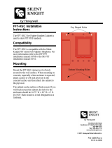 SILENT KNIGHT FFT-HSC Installation guide
-
Vectronics LP-2500 User manual
-
Air Hogs Vectron Wave User manual
-
Linear Technology 1762A-D Demo Manual
-
SpinMaster Vectron Wave Owner's manual
-
NEC E705-AVT Installation and Setup Guide
-
Vector POS TOUCH 12 WIDE Notes On Safety And Installation
-
Alesis DG8 User manual
-
Ctera C200 User guide
-
PEAK P702 L Installation And Operating
