Page is loading ...

Tiva™ TM4C123G Development Board
User's Guide
Literature Number: SPMU357B
August 2013–Revised March 2014

Contents
1 DK-TM4C123G Overview ...................................................................................................... 4
1.1 Kit Contents .................................................................................................................. 5
1.2 Using the DK-TM4C123G .................................................................................................. 5
1.3 Features ...................................................................................................................... 5
1.4 Specifications ................................................................................................................ 6
2 Hardware Description .......................................................................................................... 7
2.1 Microcontroller, USB OTG, User/Navigation Switches, User LED, and GPIO Headers (Schematic page
1) .............................................................................................................................. 8
2.1.1 Microcontroller ...................................................................................................... 8
2.1.2 USB Host/Device/OTG ............................................................................................ 8
2.1.3 User Switches and User LED .................................................................................... 9
2.1.4 GPIO Headers ...................................................................................................... 9
2.2 Data Logger, Motion Sensor, Temperature Sensors, CAN Transceiver, OLED, and SD Card
(Schematic page 2) ......................................................................................................... 9
2.2.1 Data Logger ......................................................................................................... 9
2.2.2 4-Channel Analog Measurement ................................................................................. 9
2.2.3 9-Axis Motion Sensor ............................................................................................ 10
2.2.4 Temperature Sensors ............................................................................................ 11
2.2.5 MCU Running Current ........................................................................................... 12
2.2.6 CAN Transciever ................................................................................................. 12
2.2.7 OLED Display ..................................................................................................... 13
2.2.8 SD Card ............................................................................................................ 13
2.3 Hibernate, Current Shunts, Power Supplies, Reset and Crystals (Schematic page 3) .......................... 13
2.3.1 Hibernate .......................................................................................................... 13
2.3.2 Current Shunt Resistors ......................................................................................... 14
2.3.3 Clocking ............................................................................................................ 15
2.3.4 Reset ............................................................................................................... 15
2.3.5 Power Supplies and Jumper .................................................................................... 15
2.4 Debug and Virtual COM Port (Schematic Page 4) .................................................................... 16
2.4.1 In-Circuit Debug Interface (ICDI) ............................................................................... 16
2.4.2 Virtual COM Port ................................................................................................. 17
2.5 Wireless Evaluation Module Connectors (Schematic Page 5) ...................................................... 17
3 Software Development ....................................................................................................... 18
3.1 Software Description ...................................................................................................... 18
3.2 Source Code ............................................................................................................... 18
3.3 Tool Options ................................................................................................................ 18
3.4 Programming the DK-TM4C123G Board ............................................................................... 19
A Component Locations ........................................................................................................ 20
B Bill of Materials (BOM) ....................................................................................................... 21
C References ....................................................................................................................... 24
D Schematics ....................................................................................................................... 25
E Revision History ................................................................................................................ 26
2
Contents SPMU357B–August 2013–Revised March 2014
Submit Documentation Feedback
Copyright © 2013–2014, Texas Instruments Incorporated

www.ti.com
List of Figures
1-1. Board Picture................................................................................................................ 4
2-1. DK-TM4C123G Development Board Block Diagram................................................................... 7
2-2. Can Diagram............................................................................................................... 12
2-3. Debug Out.................................................................................................................. 16
A-1. DK-TM4C123G Component Locations (Top View) ................................................................... 20
A-2. DK-TM4C123G Component Locations (Bottom View) ............................................................... 20
List of Tables
1-1. DK-TM4C123G Specifications ............................................................................................ 6
2-1. USB Host/Device/OTG Signals ........................................................................................... 8
2-2. User Switches and User LED Signals.................................................................................... 9
2-3. 4-Channel Analog Measurement Signals................................................................................ 9
2-4. 9-axis Motion Sensor Signals............................................................................................ 10
2-5. Temperature Sensor Signals............................................................................................. 11
2-6. Linear Transfer Functions for Common Temperature Ranges...................................................... 11
2-7. Microcontroller Running Current Signals............................................................................... 12
2-8. CAN Transceiver Signals................................................................................................. 12
2-9. OLED Display Signals .................................................................................................... 13
2-10. SD Card Signals........................................................................................................... 13
2-11. Power Requirements...................................................................................................... 15
2-12. Breakout Requirements................................................................................................... 15
2-13. In-Circuit Debug Interface (ICDI) Signals .............................................................................. 16
2-14. Virtual COM Port Signals................................................................................................. 17
2-15. Wireless Evaluation Module Signals.................................................................................... 17
E-1. Revision History ........................................................................................................... 26
3
SPMU357B–August 2013–Revised March 2014 List of Figures
Submit Documentation Feedback
Copyright © 2013–2014, Texas Instruments Incorporated

JTAG
Header
User/
Navigation
Switches
OLED
Graphics
Display
User
LED
Power Select
Jumper
USB Connector
(Power/ICDI)
USB Connector
(Host/Device/
OTG)
Reset
Switch
microSD
Card Slot
Power
LED
Tiva C Series
TM4C123GH6PGE
Microcontroller
9-axis
Digital Motion Sensor
SELECT/
WAKE
Button
8-Position Screw Terminal Block
for Analog Measurement and CAN
External
Temperature
Sensor
INA198
Current Shunt
Amplifier
and Current
Shunt
Resistors
CAN
Transceiver
Chapter 1
SPMU357B–August 2013–Revised March 2014
DK-TM4C123G Overview
The Tiva TM4C123G development kit is an evaluation platform for the Tiva TM4C123GH6PGE ARM®
Cortex™-M4-based series microcontrollers. The development board highlights the TM4C123GH6PGE
microcontroller's USB 2.0 On-The-Go/Host/Device (OTG/Host/Device) interface, 12-bit Analog-to-Digital
Converter (ADC), Real-Time Clock (RTC), and battery-backed Hibernation module. Figure 1-1 shows a
photo of the DK-TM4C123G.
Figure 1-1. Board Picture
All trademarks are the property of their respective owners.
4
DK-TM4C123G Overview SPMU357B–August 2013–Revised March 2014
Submit Documentation Feedback
Copyright © 2013–2014, Texas Instruments Incorporated

www.ti.com
Kit Contents
1.1 Kit Contents
The DK-TM4C123G Development Kit comes with the following:
• DK-TM4C123G development board
• On board In-Circuit Debug Interface (ICDI)
• Cables:
– Two USB Micro-B plug to USB-A plug cables (one for debug)
– USB Micro-A plug to USB-A receptacle cable
• 3-V CR2032 lithium coin-cell battery
• USB Flash drive containing:
– Complete documentation
– TivaWare™ for C Series Peripheral Driver Library and example source code
– A supported evaluation version of all of the following:
• Texas Instruments’ Code Composer Studio™ IDE
• Keil™ RealView® Microcontroller Development Kit (MDK-ARM)
• IAR Embedded Workbench® development tools
• Sourcery CodeBench™ development tools (time limited)
• GCC
1.2 Using the DK-TM4C123G
The recommended steps for using the DK-TM4C123G development kit are:
1. Follow the README First document included in the kit. The README First document will help get
the DK-TM4C123G development board up and running in minutes.
2. Use your preferred ARM tool-chain and the Tiva Peripheral Driver Library to develop an
application. Software applications are loaded using the on-board In-Circuit Debug Interface (ICDI).
See Chapter 3, Software Development, for the programming procedure. The TivaWare Peripheral
Driver Library User's Guide contains specific information on software structure and function.
3. Customize and integrate the hardware to suit an end application. This user's manual is an
important reference for understanding circuit operation and completing hardware modification.
1.3 Features
The DK-TM4C123G development kit includes the following features:
• Tiva TM4C123GH6PGE Microcontroller
• Data logger demo application
• 9-axis (accelerometer + gyro + compass) motion sensor
• 2 Analog temperature sensors
– External TMP20 temperature sensor
– Internal microcontroller temperature sensor
• Controller Area Network (CAN) transceiver
• 8 screw terminals
– 4 analog inputs (0-20 V)
– Power
– Ground
– CAN-High
– CAN-Low
5
SPMU357B–August 2013–Revised March 2014 DK-TM4C123G Overview
Submit Documentation Feedback
Copyright © 2013–2014, Texas Instruments Incorporated

Specifications
www.ti.com
• Microcontroller current shunt amplifier
• 96 x 64 color OLED display
• USB Micro-AB connector for Host/Device/OTG
• microSD card slot
• 5 navigation switches
• User LED
• Precision 3.0V reference
• Connectors for Wireless Evaluation Modules
• Available I/O brought out to headers on 0.1" grid
• Debug
– In-Circuit Debug Interface (ICDI)
– Standard 10-pin JTAG header (debug-out capable)
• Shunt resistors to measure current on V
BAT
and V
DD
• Coin cell backup battery for Hibernate mode
• Reset button
1.4 Specifications
Table 1-1 shows the specifications for the DK-TM4C123G development board.
Table 1-1. DK-TM4C123G Specifications
Parameter Value
Board supply voltage 4.75-5.25V
Dimensions 6.0" x 2.25" x 0.65" (LxWxH)
RoHS status Compliant
6
DK-TM4C123G Overview SPMU357B–August 2013–Revised March 2014
Submit Documentation Feedback
Copyright © 2013–2014, Texas Instruments Incorporated

TM4C123GH6PGE
96 x 64
Color OLED Display
MicroSD
Card Slot
User LED
Nav/User
Switches
I/O
3.3V
LDO
13V
Boost
+3.3V
+13V
Power
Select
Jumper
USB
GPIO
JTAG
GPIO
GPIO
SSI0
UART0
ICDI
Stellaris
ICDI
Debug Header
Device
USB OTG
Connector
Host
Dual
Power
Switch
Battery
VBAT
Shunts
VDD
3.0V
Ref.
VREFA+
Screw
Terminals
Temp.
Sensor
AIN20
Wireless Evaluation
Module Connector
SSI
UART
GPIO
Analog
CANTX
CANRX
AIN3
AIN2
AIN1
AIN0
AIN23
9-Axis
Motion Sensor
I2C3SCL
I2C3SDA
USB0EPEN
HIB
SSI2
+13V
XCVR
CANL
CANH
Jumper
Chapter 2
SPMU357B–August 2013–Revised March 2014
Hardware Description
The DK-TM4C123G development board includes a Tiva TM4C123GH6PGE microcontroller and an
integrated In-Circuit Debug Interface (ICDI) as well as a range of useful peripheral features (see the block
diagram in Figure 2-1). This chapter describes how these peripherals operate and interface to the
microcontroller.
Figure 2-1. DK-TM4C123G Development Board Block Diagram
7
SPMU357B–August 2013–Revised March 2014 Hardware Description
Submit Documentation Feedback
Copyright © 2013–2014, Texas Instruments Incorporated

Microcontroller, USB OTG, User/Navigation Switches, User LED, and GPIO Headers (Schematic page 1)
www.ti.com
2.1 Microcontroller, USB OTG, User/Navigation Switches, User LED, and GPIO Headers
(Schematic page 1)
2.1.1 Microcontroller
The Tiva TM4C123GH6PGE is an ARM® Cortex™-M4-based microcontroller with 256-KB flash memory,
32-KB SRAM, 80-MHz operation, USB Host/Device/OTG, Hibernation module, and a wide range of other
peripherals. See the DS-TM4C123GH6PGE microcontroller data sheet for complete device details.
Most of the microcontroller signals are routed to 0.1" pitch break-out pads and labeled with their GPIO
reference. An internal multiplexer allows different peripheral functions to be assigned to each of these
GPIO pads. When adding external circuitry, consideration should be given to the additional load on the
development board’s power rails. The Tiva PinMux Utility can be used to quickly develop pin assignments
and the code required to configure them.
The TM4C123GH6PGE microcontroller is factory-programmed with a quickstart data logger demo
program. The quickstart program resides in on-chip flash memory and runs each time power is applied,
unless the application has been replaced with a user program.
2.1.2 USB Host/Device/OTG
The DK-TM4C123G includes a USB Micro-AB (OTG) connector to allow for USB Host, Device, and OTG
operation. The following signals are used for USB OTG.:
Table 2-1. USB Host/Device/OTG Signals
GPIO Pin Pin Function USB OTG
PL6 USB0DP D+
PL7 USB0DM D-
PB0 USB0ID ID
PB1 USB0VBUS USB VBUS
Load Switch
PG4 USB0EPEN USB VBUS Power Enable (EN2)
PG5 USB0PFLT Power Fault ( OC2 )
In USB Host mode, the development board can provide power to the OTG connector. The USB0EPEN
signal controls the Channel 2 Enable (EN2) of a Texas Instruments’ TPS2052B Load Switch (U7), which
enables power to the connector's VBUS pin. The POWER SELECT jumper must be in the “ICDI” position.
In Device mode, the development board can be powered from either the ICDI or the OTG connectors. The
user can select the power source by moving the POWER SELECT jumper to the appropriate position.
In OTG mode, the POWER SELECT jumper's position requires special consideration depending on the
system and code configuration.
8
Hardware Description SPMU357B–August 2013–Revised March 2014
Submit Documentation Feedback
Copyright © 2013–2014, Texas Instruments Incorporated

www.ti.com
Data Logger, Motion Sensor, Temperature Sensors, CAN Transceiver, OLED, and SD Card (Schematic page 2)
2.1.3 User Switches and User LED
Five switches on the board provide navigation and selection for the preloaded quickstart application.
These switches can be used for other purposes in the user’s custom applications.
The development board also has a green user LED.
Table 2-2 shows how these features are connected to the pins on the microcontroller.
Table 2-2. User Switches and User LED Signals
GPIO Pin Pin Function Feature
PM0 GPIO SW1 (Up)
PM1 GPIO SW2 (Down)
PM2 GPIO SW3 (Left)
PM3 GPIO SW4 (Right)
PM4 GPIO SW5 (Select/Wake)
PG2 GPIO User LED
2.1.4 GPIO Headers
All unused pins on the microcontroller as routed out to 0.1" headers along the edges of the board and are
conveniently labeled with their port and pin names.
The remaining pins are broken out to headers located near the hardware feature that uses them. These
are also on a 0.1" grid. All of these headers are labeled with the port and pin name, and, where possible,
labeled with their function. See Schematics for detailed information on these signals.
2.2 Data Logger, Motion Sensor, Temperature Sensors, CAN Transceiver, OLED, and SD
Card (Schematic page 2)
2.2.1 Data Logger
The DK-TM4C123G comes with a quickstart application loaded into the Flash memory. This application
implements a multi-channel data logger that can measure up to four analog channels (0-20 V), nine axes
from the motion sensor, two analog temperature sensors, and the microcontroller running current.
A Windows quickstart companion application is also provided on the development kit USB flash drive and
serves as a secondary display for the Data Logger application. See Software Description for more
information.
2.2.2 4-Channel Analog Measurement
An 8-position screw terminal block is included on the development board to make easy connections to
external signals.Table 2-3 shows how the screw terminals and channels are arranged.
Table 2-3. 4-Channel Analog Measurement Signals
GPIO Pin Pin Function Terminal
- - +VBUS
PE0 AIN3 CH3
PE1 AIN2 CH2
PE2 AIN1 CH1
PE3 AIN0 CH0
- - GND
- - CANH
- - CANL
9
SPMU357B–August 2013–Revised March 2014 Hardware Description
Submit Documentation Feedback
Copyright © 2013–2014, Texas Instruments Incorporated

ADC
TERMINAL
V
1.5V
V 10.27V
0.146 0.146
u
ADC
V 0.7326mV 2048 1.5V
u u | u
REFA
ADC
12
V
3.0V
V ADCCODE ADCCODE 0.7326mV ADCCODE
4095
2 1
|
§ · § ·
¨ ¸
¨ ¸
© ¹
© ¹
ADC ADC ADC
TERMINAL
2
1 2
V V V
V
18000
0.146
R
105000 18000
R R
Data Logger, Motion Sensor, Temperature Sensors, CAN Transceiver, OLED, and SD Card (Schematic page 2)
www.ti.com
Each of the 4 channels can measure 0-20 V with an approximate 0.01 V resolution. A voltage divider on
each channel scales the 0-20 V range on the terminal to the 0-3 V range of the 12-bit Analog-to-Digital
Converter (ADC) of the TM4C123GH6PGE microcontroller. Each scaled-down signal passes through a
unity-gain amplifier to provide a low-impedance source for the microcontroller’s ADC. Below are some
useful equations to keep on hand when using the four data logger channels.
(1)
(2)
For example, if the code read from the ADC is 2048, the voltage measured by the ADC is:
(3)
Therefore the voltage being measured at the screw terminal is:
(4)
CAUTION
Exceeding the input range on either the screw terminal or the ADC pins directly
can damage the analog circuitry.
2.2.3 9-Axis Motion Sensor
Included on the development board is an InvenSense MPU-9150 digital 9-axis (accelerometer +
gyroscope + compass) motion sensor.
Sensor Features
• Accelerometer
– User-programmable full-scale ranges of ±2g, ±4g, ±8g, and ±16g
– 16-bit resolution
• Gyroscope
– User-programmable full-scale ranges of ±250 °/s, ±500 °/s, ±1000 °/s, and ±2000 °/s
– 16-bit resolution
• Magnetometer
– Full-scale range ±1200 µT
– 13-bit resolution
The sensor communicates with the TM4C123GH6PGE through an I
2
C interface. The following signals are
used:
Table 2-4. 9-axis Motion Sensor Signals
GPIO Pin Pin Function Sensor
PD0 I2C3SCL SCL
PD1 I2C3SDA SDA
PB2 GPIO INT
Please refer to the MPU-9150 data sheet for more information about the sensor.
10
Hardware Description SPMU357B–August 2013–Revised March 2014
Submit Documentation Feedback
Copyright © 2013–2014, Texas Instruments Incorporated

u
225 ADCCODE
T 147.5
4095
u
u
5
OUT
5
2.19262 10 1.8639 V
T 1481.96
3.88 10
u u u u
5 2 2
OUT
V 3.88 10 T 1.15 10 T 1.8639V
www.ti.com
Data Logger, Motion Sensor, Temperature Sensors, CAN Transceiver, OLED, and SD Card (Schematic page 2)
2.2.4 Temperature Sensors
Temperature can be measured by the Texas Instruments TMP20 Analog Temperature Sensor (U3) and/or
the internal microcontroller temperature sensor.
2.2.4.1 External TMP20 Temperature Sensor
The output of the sensor is connected directly to the microcontroller’s ADC. Table 2-5 shows the signal
used by the temperature sensor.
Table 2-5. Temperature Sensor Signals
GPIO Pin Pin Function Temp. Sensor
PE7 AIN20 V
OUT
The sensor's analog output over the -55°C to +130°C temperature range corresponds to the parabolic
transfer function (taken from the TMP20 data sheet):
where
• the temperature T is in °C (5)
Solving for temperature results in the following equation:
(6)
When only concerned with a narrow temperature range, a linear transfer function can be calculated. See
the ±2.5°C Low-Power, Analog Out Temperature Sensor Data Sheet (TMP20) for these calculations.
Table 2-6 shows the linear transfer functions for a common selection of temperature ranges.
Table 2-6. Linear Transfer Functions for Common Temperature Ranges
Temperature Range
Maximum Deviation from
Linear Equation (V)
Parabolic Equation (°C)
T
MIN
(°C) T
MAX
(°C)
-55 130 V
OUT
= –11.79mV/°C x T + 1.8528 ±1.41
-40 110 V
OUT
= –11.77mV/°C x T + 1.8577 ±0.93
-30 100 V
OUT
= –11.77mV/°C x T + 1.8605 ±0.70
-40 85 V
OUT
= –11.67mV/°C x T + 1.8583 ±0.65
-10 65 V
OUT
= –11.71mV/°C x T + 1.8641 ±0.23
35 45 V
OUT
= –11.81mV/°C x T + 1.8701 ±0.004
20 30 V
OUT
= –11.69mV/°C x T + 1.8663 ±0.004
2.2.4.2 Internal Microcontroller Temperature Sensor
The TM4C123GH6PGE microcontroller has an internal temperature sensor that can be used to notify the
system that the internal temperature is too high or low for reliable operation. The temperature sensor can
be sampled internally by the ADC. Given the ADC reading, the internal temperature, T in °C, can be
calculated as follows (taken from the TM4C123GH6PGE data sheet):
(7)
See the TM4C123GH6PGE data sheet for more information on the internal microcontroller temperature
sensor.
11
SPMU357B–August 2013–Revised March 2014 Hardware Description
Submit Documentation Feedback
Copyright © 2013–2014, Texas Instruments Incorporated

+VBUS
CH3
CH2
CH1
CH0
GND
CANH
CANL
120
Data Logger, Motion Sensor, Temperature Sensors, CAN Transceiver, OLED, and SD Card (Schematic page 2)
www.ti.com
2.2.5 MCU Running Current
The microcontroller running current I
DD
can be measured by the microcontroller itself. The output of a
Texas Instruments INA198 Current Shunt Amplifier (U15) is connected to the ADC on the microcontroller.
This amplifier increases the voltage drop on a 0.1-Ohm current shunt resistor in line with the V
DD
source
for the microcontroller. Table 2-7 shows the signal used to measure the amplifier output.
Table 2-7. Microcontroller Running Current Signals
GPIO Pin Pin Function Amplifier
PP0 AIN23 OUT
See Current Shunt Resistors for more details on calculating the running current from the ADC readings.
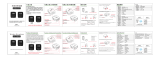
2.2.6 CAN Transciever
A Texas Instruments SN65HVD1050D High-Speed CAN Transceiver is included on the development kit.
The DK-TM4C123G can easily be connected to other CAN enabled devices via the screw terminals on the
board, see Figure 2-2.
The following signals are used for CAN:
Table 2-8. CAN Transceiver Signals
GPIO Pin Pin Function CAN Transciever
PE4 CAN0RX RXD
PE5 CAN0TX TXD
The CAN bus signals from the transceiver are brought out on the screw terminals alongside the analog
channels. Depending on the position of the development kit in the network, a termination resistor may be
required. A standard 0.125 W through-hole resistor can easily be screwed into the terminals in addition to
the bus wires. For example:
Figure 2-2. Can Diagram
12
Hardware Description SPMU357B–August 2013–Revised March 2014
Submit Documentation Feedback
Copyright © 2013–2014, Texas Instruments Incorporated

www.ti.com
Hibernate, Current Shunts, Power Supplies, Reset and Crystals (Schematic page 3)
2.2.7 OLED Display
The development board includes a 96 x 64 color Organic LED (OLED) display. The OLED display is
powered from the on-board 13 V regulator, which must be enabled before using the display.
Data is written to the display using the SSI2 peripheral. Table 2-9 shows the signals used by the display.
Table 2-9. OLED Display Signals
GPIO Pin Pin Function OLED Function
PH7 SSI2TX SDIN
PH5 SSI2FSS CS
PH4 SSI2CLK SCLK
PH6 GPIO D/C
PG1 GPIO RST
PG0 GPIO +13VEN
2.2.8 SD Card
The DK-TM4C123G features a microSD card slot. Table 2-10 shows the signals used with the SD card.
Table 2-10. SD Card Signals
GPIO Pin Pin Function SD Card Function
PA5 SSI0TX DI
PA4 SSI0RX DO
PA3 SSI0FSS CS
PA2 SSI0CLK CLK
2.3 Hibernate, Current Shunts, Power Supplies, Reset and Crystals (Schematic page 3)
2.3.1 Hibernate
The DK-TM4C123G provides a 32.768 kHz crystal (Y1) as the clock source for the TM4C123GH6PGE’s
Hibernation module. Along with a 3.0-V CR2032 lithium coin-cell backup battery that is connected to the
VBAT pin and provides power to the Hibernation module when the microcontroller is in Hibernate mode.
The current draw while in Hibernate mode can be measured indirectly by measuring the voltage across
the 1-kΩ current shunt resistor. See Current Shunt Resistors for more details.
Several conditions can generate a wake signal to the Hibernate module; waking on a Real-time Clock
(RTC) match, waking on low battery, and/or waking on assertion of the WAKE pin.
(1)
The SELECT/WAKE
switch is connected to the WAKE pin on the microcontroller. When the microcontroller is configured to
wake on WAKE assertion, the switch can be used to wake the part from Hibernate mode. The
SELECT/WAKE switch is also connected to PM4 by way of a diode to prevent PM4 from asserting WAKE
when the part enters Hibernate mode. See Appendix A: Schematics for details.
To achieve the lowest power consumption while in Hibernate mode, the HIB signal is connected to the
Channel 1 Enable (EN1) signal of the Texas Instruments TPS2052B load switch (U7). In Hibernate mode,
the HIB signal is asserted and the load switch cuts main power to the entire board, excluding the on-board
ICDI. The Hibernation module is powered solely by the back-up battery.
(1)
If the board does not turn on when you connect it to a power source, the microcontroller might be in Hibernate mode (depending on the
programmed applications). You must satisfy one of the programmed wake conditions and connect the power to bring the microcontroller
out of Hibernate mode and turn on the board.
13
SPMU357B–August 2013–Revised March 2014 Hardware Description
Submit Documentation Feedback
Copyright © 2013–2014, Texas Instruments Incorporated

SHUNT SHUNT
DD
SHUNT
V V
I
R 1000
§ ·
¨ ¸
© ¹
ADC
VDDSHUNT ADC
DD
VDDSHUNT
V
V V
100
I
R 0.1 10
u u
ADC VDDSHUNT VDDSHUNT
V V Gain V 100
VDDSHUNT VDDSHUNT
DD
VDDSHUNT
V V
I
R 0.1
Hibernate, Current Shunts, Power Supplies, Reset and Crystals (Schematic page 3)
www.ti.com
The DK-TM4C123G has additional circuitry that allows the development board to be turned on when a
battery is not present or when the battery voltage is too low. A Texas Instruments TPS3803-01 Voltage
Detector (U12) monitors V
BAT
and produces a VBAT_GOOD signal when the battery voltage is above 2.1
V. Using standard logic gates and the state of V
BAT
and V
DD
, the HIB signal can be forced high when V
BAT
is not valid and the microcontroller is not already powered. With this circuit, a USB-powered board can
turn itself on when the back-up battery is either missing or fully discharged. See Appendix A: Schematics
for more details.
This additional circuitry may not be needed in all applications. For example, when using the Hibernate
module in VDD3ON mode, power is cut to the microcontroller internally which eliminates the need to turn
off an external supply using HIB. By default the DK-TM4C123G is not configured to use VDD3ON mode;
HIB is connected to the load switch, WAKE is pulled up to V
BAT
, and V
BAT
is connected to the battery.
VDD3ON mode can be used if the board is reconfigured as follows
(2)
: Disconnect HIB from the load swich
by removing the HIB DISC jumper (JP3). Next, ensure that WAKE is pulled HIGH either by leaving the
battery connected or by removing the battery and connecting V
BAT
to V
DD
.
CAUTION
Failure to remove the battery when connecting V
BAT
to V
DD
will damage the
battery and can cause a fire.
There are many different ways that Hibernate mode can be implemented in an embedded system. Each
implementation requires its own special design considerations.
2.3.2 Current Shunt Resistors
The development board provides two current shunt resistors to measure the MCU running current, I
DD
, and
the hibernation battery current, I
VBAT
. I
DD
can be measured by the MCU through a TI INA198 Current Shunt
Amplifier (U15). See MCU Running Current section. I
BAT
must be measured externally.
2.3.2.1 Microcontroller Running Current I
VDD
The shunt resistor for I
DD
, R
VDDSHUNT
, is 0.1Ω and the INA198 amplifier gain is 100 V/V. Therefore:
(8)
(9)
Given the ADC measurement, you can calculate I
VDD
:
(10)
Or simply, 10mV per mA.
2.3.2.2 Hibernation Battery Current I
BAT
The shunt resistor for I
VBAT
, R
VBATSHUNT
, is 1kΩ.
(11)
Or simply 1 mV per µA.
(2)
In addition to reconfiguring the hardware, the software must also be reconfigured to use VDD3ON mode.
14
Hardware Description SPMU357B–August 2013–Revised March 2014
Submit Documentation Feedback
Copyright © 2013–2014, Texas Instruments Incorporated

www.ti.com
Hibernate, Current Shunts, Power Supplies, Reset and Crystals (Schematic page 3)
2.3.3 Clocking
The DK-TM4C123G uses a 16.0-MHz crystal (Y2) to complete the TM4C123GH6PGE microcontroller's
main internal clock circuit. An internal PLL, configured in software, multiplies this clock to higher
frequencies for core and peripheral timing.
The Hibernation module is clocked off of an external 32.768 kHz crystal (Y1).
2.3.4 Reset
The RESET signal into the TM4C123GH6PGE microcontroller connects to the RESET switch and to the
ICDI circuit for a debugger-controlled reset.
External reset is asserted (active low) under any one of these conditions:
• Power-on reset
• RESET switch held down
• By the ICDI circuit when instructed by the debugger (this capability is optional, and may not be
supported by all debuggers).
The OLED display has special reset timing requirements requiring a dedicated control line from the
microcontroller.
2.3.5 Power Supplies and Jumper
The DK-TM4C123G can be powered from one of two power sources:
• ICDI USB cable (default)
• USB OTG cable
A moveable jumper shunt on the POWER SELECT headers is used to select one of the two power
sources. Only one source should be selected at a time.
See USB Host/Device/OTG for the recommended jumper positions for the specific USB modes.
The development board is designed to provide power to a limited amount of external circuitry. Table 2-11
shows the board’s power requirements and Table 2-12 shows the board’s breakout limitations.
Table 2-11. Power Requirements
Board Supply Min Typical Max Unit
ICDI USB Cable
4.75 5 5.25 V
USB OTG Cable
Table 2-12. Breakout Requirements
Breakout Condition Max Unit
+3.3V 260 mA
+3.3V at 260mA, OLED on 350 mA
+5.0V
(1) (2)
+3.3V at 260mA, OLED off 380 mA
(1)
This represents the +5.0V breakout and the +V
BUS
breakout. Total current = I
5V
+ I
VBUS
(2)
+5.0V is switched by the load switch (U7); however +V
BUS
is always connected.
15
SPMU357B–August 2013–Revised March 2014 Hardware Description
Submit Documentation Feedback
Copyright © 2013–2014, Texas Instruments Incorporated

GND
TDI
TDO
TCK
TMS
Install Jumper
Debug and Virtual COM Port (Schematic Page 4)
www.ti.com
2.4 Debug and Virtual COM Port (Schematic Page 4)
2.4.1 In-Circuit Debug Interface (ICDI)
The DK-TM4C123G development board comes with an on-board In-Circuit Debug Interface (ICDI). The
ICDI allows for programming and debugging of the TM4C123GH6PGE using LM Flash Programmer
and/or any of the supported tool chains. Both JTAG and Serial Wire Debug (SWD) are supported.
An external debugger can be connected to the development board through the 2 x 5 fine pitch (0.05”)
ARM JTAG header (J1). When connecting an external debugger, pin 3 of the JTAG header must be tied
to ground in order for the ICDI to release control of the JTAG signals. The ARM standard pinout specifies
pin 3 as ground, therefore, any standard third-party debugger should work.
Table 2-13 shows the pins used for JTAG and SWD.
Table 2-13. In-Circuit Debug Interface (ICDI) Signals
GPIO Pin Pin Function JTAG Header Pin
PC0 TCK/SWCLK 4
PC1 TMS/SWDIO 2
PC2 TDI 8
PC3 TDO/SWO 6
RST RST 10
ICDI Function
- EXTDBG 3
See Appendix A: Schematics for the full header pinout.
In addition, the ICDI can debug an external target using the header locations near the JTAG connector.
The on-board TM4C123GH6PGE must be held in reset by installing a 2-pin jumper in the DEBUG OUT
EN jumper position (JP1). The HIB DISC (located near the SELECT/WAKE button) is a conveniently
available jumper to repurpose. The following diagram illustrates how an external target can be connected.
In this configuration, the debugger will not have control of the hardware reset line RST.
Figure 2-3. Debug Out
16
Hardware Description SPMU357B–August 2013–Revised March 2014
Submit Documentation Feedback
Copyright © 2013–2014, Texas Instruments Incorporated

www.ti.com
Wireless Evaluation Module Connectors (Schematic Page 5)
2.4.2 Virtual COM Port
When plugged into a PC, the device enumerates as a debugger and a virtual COM port. The COM port is
connected to the following pins on the MCU.
Table 2-14. Virtual COM Port Signals
GPIO Pin Pin Function Virtual COM Port
PA0 U0RX TXD
PA1 U0TX RXD
2.5 Wireless Evaluation Module Connectors (Schematic Page 5)
The DK-TM4C123G features a set of Wireless Evaluation Module connectors. Table 2-15 lists the features
that are brought out on the connectors.
Table 2-15. Wireless Evaluation Module Signals
GPIO Pin Pin Function EM Function EM 1 (J9) Pin
PF0 U1RTS CTS 3
PC5 U1TX RX 7
PC4 U1RX TX 9
PF7 I2C2SDA SDA 11
PF6 I2C2SCL SCL 13
PC6 GPIO GPIO0 10
PC7 GPIO GPIO1 12
PH1 SSI3FSS CS 14
PH0 SSI3CLK SCLK 16
PH3 SSI3TX MOSI 18
PH2 SSI3RX MISO 20
GPIO Pin Pin Function EM Function EM 2 (J10) Pin
PF5 GPIO GPIO2 13
PF3 GPIO RST 15
PF2 GPIO SHUTD 19
PF1 U1CTS RTS 18
PF4 GPIO GPIO3 20
Refer to the specific wireless evaluation module user’s guide to determine compatibility.
A list of Wireless Evaluation Modules available for sale can be found on the TI eStore. Search for
"CC*EM*" as a Part Number on the Advanced Search page.
17
SPMU357B–August 2013–Revised March 2014 Hardware Description
Submit Documentation Feedback
Copyright © 2013–2014, Texas Instruments Incorporated

Chapter 3
SPMU357B–August 2013–Revised March 2014
Software Development
This chapter provides general information on software development as well as instructions for flash
memory programming.
3.1 Software Description
The software provided with the DK-TM4C123G provides access to all of the peripheral devices supplied in
the design. The TivaWare™ for C Series Peripheral Driver Library is used to operate the on-chip
peripherals.
The software includes a set of example applications that use the TivaWare™ Peripheral Driver Library.
These applications demonstrate the capabilities of the TM4C123GH6PGE microcontroller, as well as
provide a starting point for the development of the applications for use on the DK-TM4C123G
development board.
The DK-TM4C123G Development Kit USB flash drive also contains a Windows quickstart companion for
the Data Logger quickstart application. The companion application provides a strip-chart display for up to
16 channels of data from the DK-TM4C123G development board. The display for each channel can be
enabled or disabled and the data logged a comma-separated values (CSV) file.
3.2 Source Code
The complete source code is provided on the DK-TM4C123G USB flash drive including the source code
for the Windows quickstart companion application. See the README First document for a detailed
description of hardware setup and how to install the source code. The source code and binary files are
installed in the TivaWare™ software tree.
3.3 Tool Options
The source code installation includes directories containing projects and makefiles for the following tool-
chains:
• Keil ARM RealView® Microcontroller Development System
• IAR Embedded Workbench for ARM
• Sourcery Codebench
• Generic GNU C Compiler
• Texas Instruments' Code Composer Studio™ IDE
Download evaluation versions of these tools from the Tools & Software section of www.ti.com/tiva. Due to
code size restrictions, the evaluation tools may not build all example programs. A full license is necessary
to re-build or debug all examples.
Instructions on installing and using each of the evaluation tools can be found in the Quickstart guides (for
example, in the Keil Quickstart or IAR Quickstart) which are also available for download from the Tools &
Software section of www.ti.com/tiva.
For detailed information on using the tools, see the documentation included in the tool chain installation or
visit the website of the tools supplier.
18
Software Development SPMU357B–August 2013–Revised March 2014
Submit Documentation Feedback
Copyright © 2013–2014, Texas Instruments Incorporated

www.ti.com
Programming the DK-TM4C123G Board
3.4 Programming the DK-TM4C123G Board
The DK-TM4C123G software package includes pre-built binaries for each of the example applications. If
you installed the TivaWare™ software to the default installation path of C:\ti\TivaWare_C_Series-x.x, you
can find the example applications in C:\ti\TivaWare_C_Series-x.x\examples\boards\dk-tm4c123g. The on-
board ICDI is used with the LM Flash Programmer tool to program applications on the DK-TM4C123G
board.
Follow these steps to program example applications into the DK-TM4C123G development board using the
ICDI:
1. Install the Stellaris ICDI drivers on a Windows PC. Refer to the Stellaris Driver Installation Guide.
2. Install LM Flash Programmer on the PC.
3. Connect the USB-A cable plug to an available port on the PC and the Mini-B plug to the board.
4. Verify that the POWER LED D4 on the board is lit.
5. Run LM Flash Programmer.
6. In the Configuration tab, use the Quick Set control to select the DK-TM4C123G development board.
7. Move to the Program tab and click the Browse button. Navigate to the example applications directory
(the default location is C:\ti\TivaWare_C_Series-x.x\examples\boards\dk-tm4c123g\).
8. Each example application has its own directory. Navigate to the example directory that you want to
load and then into the directory that contains the binary (*.bin) files. Select the binary file and click
Open.
9. Set the “Erase Method ” to “Erase Necessary Pages,” check the “Verify After Program” box, and check
“Reset MCU After Program”.
10. Click the Program button to start the Erase, Download, and Verify process. The DEBUG ACTIVE LED
(D5) on the board turns on at this time.
Program execution starts once the Verify process is complete.
19
SPMU357B–August 2013–Revised March 2014 Software Development
Submit Documentation Feedback
Copyright © 2013–2014, Texas Instruments Incorporated

Appendix A
SPMU357B–August 2013–Revised March 2014
Component Locations
Figure A-1. DK-TM4C123G Component Locations (Top View)
Figure A-2. DK-TM4C123G Component Locations (Bottom View)
20
Component Locations SPMU357B–August 2013–Revised March 2014
Submit Documentation Feedback
Copyright © 2013–2014, Texas Instruments Incorporated
/