Page is loading ...

Application Report
SLAA593–September 2013
ADC Input Protection
Shridhar Atmaram More .................................................................................. Digital/Analog Converters
ABSTRACT
Analog-to-Digital Converters (ADC’s) are at the heart of any design which involves capturing the analog
signal. This is usually the most important and highest-cost component in the signal chain. Since the signal
chain is interfaced to the varying analog world signals, it is critical to protect the ADC inputs. This
application note lists different techniques to protect the ADC inputs from the signals which can be beyond
the ADC specifications.
Contents
1 Introduction .................................................................................................................. 1
2 Operational Amplifier Power Supply ...................................................................................... 2
3 Input Protection Using Clamps ............................................................................................ 2
4 Operational Amplifiers With Output Clamp .............................................................................. 3
5 Conclusion ................................................................................................................... 3
6 References ................................................................................................................... 3
1 Introduction
The ADC inputs can get damaged by signals exceeding the input range specified in the electrical
parameters. The inputs need to be protected all the time (during powered up as well as powered down
state) to avoid damaging the ADC. The damage due to overstress can be catastrophic, that is, the ADC
will not be functional, or there will be performance degradation to the extent that expected system
performance cannot be achieved.
The methods discussed below are applicable to ADCs which have the front end as the sample and hold
block or the max input range is limited by analog supply voltage. There are ADCs in the market which can
support higher input voltage than the analog supply voltage. These ADCs use resistive input combination
to level shift the actual ADC input. It is recommended to have a operational amplifier buffer drive these
inputs and the buffer power supply should fall within absolute max input ratings of the ADC.
1
SLAA593–September 2013 ADC Input Protection
Submit Documentation Feedback
Copyright © 2013, Texas Instruments Incorporated

Operational Amplifier Power Supply
www.ti.com
2 Operational Amplifier Power Supply
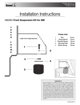
Most ADC inputs are preceded by an operational amplifier stage. Check if the operational amplifier can be
operated with same input supply as that of the ADC. This configuration ensures that the input to ADC will
never go beyond the ADC supply range since the operational amplifier will get saturated when the output
gets close to supply rails, thus protecting the ADC inputs. This is the simplest way of protecting the inputs.
Please refer the configuration shown in Figure 1.
Figure 1. Operational Amplifier Power Supply
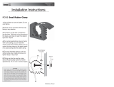
3 Input Protection Using Clamps
This protection method can be employed if the input is directly connected to the ADC input or the signal
conditioning amplifiers are operating at voltages greater than the ADC analog supply voltage. Most ADC
inputs have the internal diodes, which conduct when the input voltage goes beyond the supply voltage.
These diodes are not designed to carry large current for a longer amount of time. The clamp structure
emulates the ADC internal diode structure with external clamp diodes which are capable of higher
continuous current conduction. Placing these clamps after the input anti-aliasing RC filter provides an
additional advantage. The resistance acts as a current limiting device if the input voltage goes beyond
allowed input range. If the current is too high, this resistance will get damaged due to heat dissipation and
will protect the clamp diodes as well as ADC.
Figure 2. Input Protection Using Clamps
2
ADC Input Protection SLAA593–September 2013
Submit Documentation Feedback
Copyright © 2013, Texas Instruments Incorporated

www.ti.com
Operational Amplifiers With Output Clamp
4 Operational Amplifiers With Output Clamp
Clamp diodes have an important parameter to consider “reverse recovery time”. Once the ADC input gets
back in the normal range from overdrive condition, the diodes are expected to turn off immediately and
normal operation restored. During reverse recovery period the clamp diode will still conduct. If it is
important to have a short reverse recovery time, consider using operational amplifiers with programmable
output clamp levels. OPA698 is one such device with ultra-fast overdrive recovery (1 ns) and wide
operating bandwidth. The circuit configuration shown in Figure 3 illustrates the OPA698 interface with
ADS822 ADC.
Figure 3. Single-Supply Limiting ADC Input Driver
5 Conclusion
It is important to protect the ADC, an integral part of the data acquisition system, from all possible input
scenarios. The methods described in this application report help in designing a system which will be
protected from unwanted signal fluctuations. Before implementing any of these methods, it is important to
know ADC specifications as well as ADC input structure and signal path processing requirements.
6 References
1. OPA698 datasheet SBOS258
3
SLAA593–September 2013 ADC Input Protection
Submit Documentation Feedback
Copyright © 2013, Texas Instruments Incorporated

IMPORTANT NOTICE
Texas Instruments Incorporated and its subsidiaries (TI) reserve the right to make corrections, enhancements, improvements and other
changes to its semiconductor products and services per JESD46, latest issue, and to discontinue any product or service per JESD48, latest
issue. Buyers should obtain the latest relevant information before placing orders and should verify that such information is current and
complete. All semiconductor products (also referred to herein as “components”) are sold subject to TI’s terms and conditions of sale
supplied at the time of order acknowledgment.
TI warrants performance of its components to the specifications applicable at the time of sale, in accordance with the warranty in TI’s terms
and conditions of sale of semiconductor products. Testing and other quality control techniques are used to the extent TI deems necessary
to support this warranty. Except where mandated by applicable law, testing of all parameters of each component is not necessarily
performed.
TI assumes no liability for applications assistance or the design of Buyers’ products. Buyers are responsible for their products and
applications using TI components. To minimize the risks associated with Buyers’ products and applications, Buyers should provide
adequate design and operating safeguards.
TI does not warrant or represent that any license, either express or implied, is granted under any patent right, copyright, mask work right, or
other intellectual property right relating to any combination, machine, or process in which TI components or services are used. Information
published by TI regarding third-party products or services does not constitute a license to use such products or services or a warranty or
endorsement thereof. Use of such information may require a license from a third party under the patents or other intellectual property of the
third party, or a license from TI under the patents or other intellectual property of TI.
Reproduction of significant portions of TI information in TI data books or data sheets is permissible only if reproduction is without alteration
and is accompanied by all associated warranties, conditions, limitations, and notices. TI is not responsible or liable for such altered
documentation. Information of third parties may be subject to additional restrictions.
Resale of TI components or services with statements different from or beyond the parameters stated by TI for that component or service
voids all express and any implied warranties for the associated TI component or service and is an unfair and deceptive business practice.
TI is not responsible or liable for any such statements.
Buyer acknowledges and agrees that it is solely responsible for compliance with all legal, regulatory and safety-related requirements
concerning its products, and any use of TI components in its applications, notwithstanding any applications-related information or support
that may be provided by TI. Buyer represents and agrees that it has all the necessary expertise to create and implement safeguards which
anticipate dangerous consequences of failures, monitor failures and their consequences, lessen the likelihood of failures that might cause
harm and take appropriate remedial actions. Buyer will fully indemnify TI and its representatives against any damages arising out of the use
of any TI components in safety-critical applications.
In some cases, TI components may be promoted specifically to facilitate safety-related applications. With such components, TI’s goal is to
help enable customers to design and create their own end-product solutions that meet applicable functional safety standards and
requirements. Nonetheless, such components are subject to these terms.
No TI components are authorized for use in FDA Class III (or similar life-critical medical equipment) unless authorized officers of the parties
have executed a special agreement specifically governing such use.
Only those TI components which TI has specifically designated as military grade or “enhanced plastic” are designed and intended for use in
military/aerospace applications or environments. Buyer acknowledges and agrees that any military or aerospace use of TI components
which have not been so designated is solely at the Buyer's risk, and that Buyer is solely responsible for compliance with all legal and
regulatory requirements in connection with such use.
TI has specifically designated certain components as meeting ISO/TS16949 requirements, mainly for automotive use. In any case of use of
non-designated products, TI will not be responsible for any failure to meet ISO/TS16949.
Products Applications
Audio www.ti.com/audio Automotive and Transportation www.ti.com/automotive
Amplifiers amplifier.ti.com Communications and Telecom www.ti.com/communications
Data Converters dataconverter.ti.com Computers and Peripherals www.ti.com/computers
DLP® Products www.dlp.com Consumer Electronics www.ti.com/consumer-apps
DSP dsp.ti.com Energy and Lighting www.ti.com/energy
Clocks and Timers www.ti.com/clocks Industrial www.ti.com/industrial
Interface interface.ti.com Medical www.ti.com/medical
Logic logic.ti.com Security www.ti.com/security
Power Mgmt power.ti.com Space, Avionics and Defense www.ti.com/space-avionics-defense
Microcontrollers microcontroller.ti.com Video and Imaging www.ti.com/video
RFID www.ti-rfid.com
OMAP Applications Processors www.ti.com/omap TI E2E Community e2e.ti.com
Wireless Connectivity www.ti.com/wirelessconnectivity
Mailing Address: Texas Instruments, Post Office Box 655303, Dallas, Texas 75265
Copyright © 2013, Texas Instruments Incorporated
/