
1
The Motivation.
ELECTRONIC WHEELCHAIR
SERVICE MANUAL
GB
ELECTRONIC WHEELCHAIR
OPTIMUS

2
Table of contents
Foreword ................................................................................................................................4
Technical Specifications ................................................................................................................... 4
Drive unit................................................................................................................................ 5
Carbon brushes ................................................................................................................................ 5
Removal....................................................................................................................................... 5
Fitting.......................................................................................................................................... 6
Collector ...................................................................................................................................... 6
Replacing the drive unit .................................................................................................................. 7
Preparations................................................................................................................................ 7
Removal....................................................................................................................................... 8
Fitting........................................................................................................................................ 10
Functional checks ..................................................................................................................... 10
Brakes.................................................................................................................................... 11
Motor brake ................................................................................................................................... 11
Functionality ............................................................................................................................ 11
Drum Brakes ................................................................................................................................... 12
Adjusting................................................................................................................................... 12
Replacing the bowden cable ................................................................................................... 13
Magnetic brake .............................................................................................................................. 14
Functionality ............................................................................................................................ 14
Removal..................................................................................................................................... 15
Fitting........................................................................................................................................ 15
Adjusting................................................................................................................................... 16
Functional checks ..................................................................................................................... 16
Replacing the bowden cable ................................................................................................... 17
Steering ................................................................................................................................19
Replacement ................................................................................................................................... 19
Removal..................................................................................................................................... 19
Fitting........................................................................................................................................ 20
Alignment....................................................................................................................................... 21
Checking the alignment ..........................................................................................................21
Adjusting the alignment .........................................................................................................21
Setting the director ....................................................................................................................... 22
Tyres ...................................................................................................................................... 23
Changing the tyres ........................................................................................................................ 23
All wheels .................................................................................................................................. 23
Front wheels ............................................................................................................................. 24
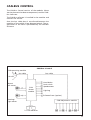
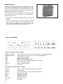
CAN-Bus Control .................................................................................................................. 25
CAN-Bus hardware......................................................................................................................... 26
Operating module.................................................................................................................... 26
Power module........................................................................................................................... 28
Plug assignment ....................................................................................................................... 28
Adjustment module ................................................................................................................. 29
Plug assignment ....................................................................................................................... 29
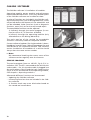
CAN-Bus software .......................................................................................................................... 30
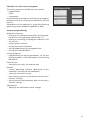
Service program ....................................................................................................................... 30
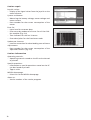
Driving programs ..................................................................................................................... 33
Programming with the operating module ................................................................................... 34
Adjustment modus................................................................................................................... 34
Programming foil ..................................................................................................................... 34
Switching to the adjustment modus ...................................................................................... 35
Functions................................................................................................................................... 35

3
Adjusting the joystick priority ................................................................................................ 35
Adjustment of the parameters ............................................................................................... 36
Concluding the adjustment modus ........................................................................................ 37
Quick reset to standard values ............................................................................................... 37
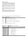
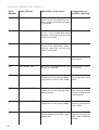
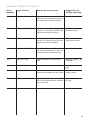
CAN-Bus error list .......................................................................................................................... 38
Replacing the CAN-Bus modules .................................................................................................. 44
Replacement (all modules) ...................................................................................................... 44
Checking the cable layout .......................................................................................................45
Lighting................................................................................................................................. 46
Replacing lightbulbs ...................................................................................................................... 46
Adjusting the headlights .............................................................................................................. 46
Batteries ............................................................................................................................... 47
Charge............................................................................................................................................. 47
Battery chargers............................................................................................................................. 47
Types of batteries........................................................................................................................... 48
Maintenance of liquid batteries ............................................................................................. 49
Replacement ................................................................................................................................... 49
Removal..................................................................................................................................... 49
Fitting........................................................................................................................................ 49
Fuses...................................................................................................................................... 50
Battery fuse .................................................................................................................................... 50
Electronic security.......................................................................................................................... 50
Maintenance......................................................................................................................... 51
Maintenance checklist ................................................................................................................... 52
Electrical system ....................................................................................................................... 52
Mechanic ................................................................................................................................... 53
DIN norms and guidelines ....................................................................................................... 54
Notes ..................................................................................................................................... 55

4
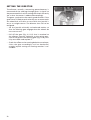
FOREWORD
This service manual is designated for the authorized
dealer.
It is complemented with the according users manual
and the spare parts list. – A users manual is supplied
with each vehicle. Spare parts lists and operating man-
uals can be ordered at the manufacturer.
The work may only be done by professionally educat-
ed personnel.
TECHNICAL SPECIFICATIONS
The indicated performance is only realistic under the
following circumstances:
– Surrounding temperature 27° C
– 100% nominal battery capacity in accordance with
DIN standard
– Mint condition batteries with more than 5 charging
cycles
– Nominal load of 75 kg
– Without repeated acceleration
– Level and firm surface
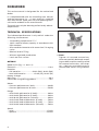
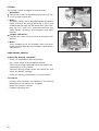
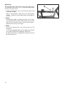
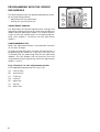
OPTIMUS
Model 3.622 (fig. 1–1 and 1–2)
Electronic ...............................................................110 A
Batteries:
– Gel batteries....................... 60 Ah (20h), 80 Ah (20h)
– Lead acid batteries ................ 60 Ah (5h), 90 Ah (5h)
Battery charger
Main fuse .................................................................80 A
Permissible rising/falling gradient: ........................18%
Motor:
– Constant performance 6 km/h .........................300 W
– Constant performance 10 km/h .......................500 W
Range:
– with 60-Ah-gel-batteries (6 km/h) ................... 40 km
– with 80-Ah-gel-batteries (6 km/h) ................... 60 km
– with 80-Ah-gel-batteries (10 km/h) ................. 40 km
– with 60-Ah-lead-acid-batteries (6 km/h) ......... 50 km
– with 90-Ah-lead-acid-batteries (6 km/h) ......... 70 km
– with 90-Ah-lead-acid-batteries (10 km/h) ....... 50 km
Speed:
– serial.................................................................. 6 km/h
– optional .......................................................... 10 km/h
1–1
1–2
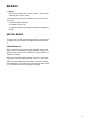
☞ Note:
Tighten all screwed connections,
when not specially declared, accord-
ing to table torque according to DIN
for screwed connections, view chap-
ter < Maintenance/Maintenance
checklist/DIN norms and guidelines
>.

5
b
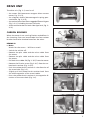
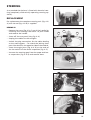
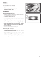
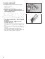
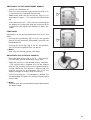
DRIVE UNIT
The drive unit (fig. 2–1) consists of
– the motor (24V-permanent magnet direct current
motor, fig. 2–2/ A),
– the magnetic brake (electromagnetic spring pres-
sure brake, fig. 2–2/ B),
– the maintenance free direct cogged differential gear
(fig. 2–2/ C) including the two half axles
– and the drum brakes on both sides (optional, fig. 2–
2/ D).
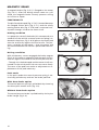
CARBON BRUSHES
When the motor is not running flawless and defects in
the incoming lines can be excluded the four carbon
brushes have to be checked one after the other.
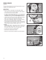
REMOVAL
☞ Note:
Watch for the screws. – Will be re-used!
– Switch the vehicle off.
– Remove the plus cable and the minus cable from
the motor.
– Remove the plus cable and the minus cable from
the motor.
– Pull back the rubber lid (fig. 2–3/ E) from the motor.
– Remove the fixation screw (fig. 2–4/ F) from the car-
bon brush retainer (fig. 2–4/ G).
– Push the carbon brush retainer in the direction of
the screw hole (fig. 2–5).
– Slightly pull the carbon brush retainer back form
the motor opposite of the screw holder.
– Press the carbon brush retainer in the opposite di-
rection of the screw hole (fig. 2–6).
2–1
2–2
2–3
2–4
2–5
A B
C
D
E
F
g
1
2

6
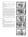
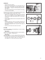
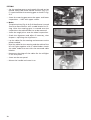
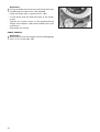
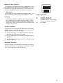
– Slightly pull out the carbon brush retainer (fig. 2–
7).
☞ Note:
Two opposite carbon brushes each are connected
to each other by a cable (fig. 2–8/ H) running inside
the motor.
– Remove the philister head screw (fig. 2–9/ I) of the
connecting cable.
– Completely remove the carbon brush retainer.
☞ Note:
1.) The carbon brush retainers cannot be pulled
straight out of the opening. – Slightly turn the car-
bon brush retainer sideways while pulling it out.
☞ The carbon brushes are worn when the pressure
springs come to rest on the retainer without the
carbon brushes reaching over their guide way. They
are also to be replaced when contacts (fig. 2–10/ K)
appear black and blunt. – On intact carbon brushes
the contacts are anthracite coloured and shining.
☞ When one or more carbon brushes are extremely or
totally worn, all carbon brushes are to be ex-
changed. – As a spare part the carbon brushes are
supplied in a set completely assembled in the retain-
er.
– If the carbon brush is completely intact reassemble
the carbon brush retainer and check the next one.
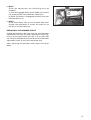
FITTING
The fitting is done analogue in reverse order.
COLLECTOR
The collector (fig. 2–10/ L) located between the carbon
brushes is also to be checked for damages. – To check
them remove a carbon brush retainer.
☞ Note:
The slight grinding marks caused by the carbon
brushes correspond to their normal wear and have
no influence on the performance of the motor. Ex-
treme recesses have to be smoothed out. If partial
segments have been broken out or are extremely
burnt the drive unit has to be replaced.
2–6
2–7
2–8
2–9
2–10
I
l
K
H

7
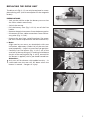
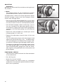
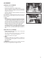
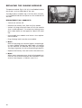
REPLACING THE DRIVE UNIT
The drive unit (fig. 2–11) can only be replaced as a com-
plete driving unit (with the exception of the magnetic
brakes).
PREPARATIONS
– Jack up the vehicle under the battery case so that
the front wheels move freely.
– Swivel the seat up.
– Pull the battery fuse (fig. 2–12/ A) out of the fuse
holder.
– Remove the pole shoe covers from the battery poles.
– Disconnect all four cable connections from the bat-
tery poles (fig. 2–13/ B).
– Prevent the seat from swivelling down (for exam-
ple with a wood strip between the seat and chassis).
☞ Note:
Slight tension can occur on wheelchairs with seat
inclination adjustment (Code 118) of the seat low-
ered completely. – Adjust to a tension free position.
– Carefully turn the button (fig. 2–14/ C) off of the
seat lock without pulling on it. In doing so hold onto
the pin of the seating lock (fig. 2–14/ D), onto which
the button is applied, with a pan head screwdriver.
!
Attention:
Only turn off the button with added security. – In
unsecured state the seat will fall down when the
button is moved. – Danger of injury!
2–11
2–12
2–14
2–13
A
B
D
C

8
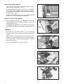
With drum brake option
– Screw off the ball button of the drive-/push- opera-
tion selection lever (fig. 2–15/ E).
– Pull the brake lever (fig. 2–16/ F) off. – To achieve
this remove the hexagon socket thread pin (fig. 2–
16/ G) from the bushing into which the eccentric
reaches (fig. 2–16/ H).
– Remove the bowden cables on both sides from the
brake arms, view chapter < drum brakes >.
Without drum brake option
– Pull the brake lever off. – To achieve this screw the
inner hexagon socket thread pin (fig. 2–17/ I) out of
the eccentric shaft.
– Disengage the bowden cable from the motor and
the magnetic brake, view chapter < magnetic brake
>.
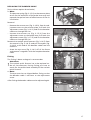
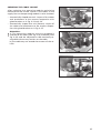
REMOVAL
– Demount the two front wheels. – For this remove
the four screws for the wheel attachment (view fig.
2–18).
– Take the front and both side panels off (fig. 2–19).
– Loosen the spanning belt that straps the batteries
in (view chapter < batteries/replacement >) and re-
move the batteries.
– Lift out the battery case (fig. 2–19/ K).
2–17
2–15
2–16
2–18
E
K
H
G
F
I
2–19

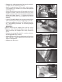
9
– Remove the cable connections for the plus and mi-
nus pole on the motor (fig. 2–20/ L).
– Open all cable binders of the right cable harness.
Cut through any binders that cannot be opened
(view fig. 2–21).
– Unlock the plug connectors of the speed sensor, the
magnetic brake and the micro-switch for push
modus, remove them from the power module and
extract the cable harness. – To unlock the locking
levers press them down on the opposite side of the
module.
– Lever off the ball ladle of the transverse control arm
after removing the security hanger (fig. 2–22/ M).
– Screw the stopper discs (fig. 2–23/ N) off of the rock-
er. – While doing so observe the following danger
indications!
!
Attention:
When removing the stopper discs hold on to the
drive so that it cannot fall down (view fig. 2–24).
After removing the stopper discs slowly lower the
drive.
– Remove the springs (fig. 2–26/ O) as well as the low-
er spring guides (fig. 2–26/ P).
– Screw off the screws for the attachment of the drive
(fig. 2–25/ Q). – While doing so secure the drive
against falling down.
– Remove the drive unit
2–20
2–21
2–22
N
M
l
2–23
2–24

10
FITTING
The fitting is done analogue in reverse order.
!
Attention:
Secure the screws for attaching the drive unit (fig.
2–26/ R) with Loctite 243!
☞ Note:
The cable harness has to be repositioned. Guide the
cable in font of the resting plate (fig. 2–26/ S) and
underneath the shaft for the brake lever (also com-
pare fig. 2–17 and 2–21). Afterward refasten the
cable harness to chassis and sea again with cable
binders.
Torque indication:
Tighten the screws for the wheel attachment with
20 Nm!
☞ Note:
After completion of all assembly work the drum
brake has to be adjusted, view chapter < drum brake/
adjustment >.
FUNCTIONAL CHECKS
Inspection during standstill
– Check all attachments and connections.
– Do a visual check of the complete vehicle.
– Switch to pushing mode and check the smooth ma-
noeuvrability of the vehicle.
– Switch to driving mode, switch the vehicle on and
check the battery voltage.
– Check all lighting components for functionality.
Test drive
– Initially drive carefully and observe if the driving
behaviour of the vehicle has changed.
– Watch for unusual sounds.
– Conduct a braking test.
2–25
2–26
R
Q
P
O
S

11
BRAKES
☞ Note:
Switch the vehicle off in push mode. – This makes
pushing the vehicle easier.
The vehicle is fitted with a double security system, con-
sisting of:
– the drum brake (option),
– the motor brake and
– an electro-magnetic spring pressure brake (magnetic
brake).
MOTOR BRAKE
The function of the motor brake evolves by the type
of approach of the motor through the power electron-
ic.
FUNCTIONALITY
With retracted driving lever the induced motor volt-
age is short circuited by a programmable tacting fre-
quency that continuously brakes the vehicle down to
almost stillstand.
With the programmable tacting frequency the brak-
ing process can be adjusted from "soft" to "full-stop".
When traveling downhill the motor switches to gener-
ator operation. This effects that the energy won is fed
in to the drive batteries (energy recycling).

12
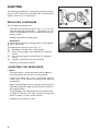
DRUM BRAKES
(Option)
The two drum brakes for the driving wheels are acti-
vated by the hand brake lever.
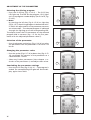
ADJUSTING
The drum brake is adjusted via the bowden cable.
– Jack up the vehicle and disassemble the front wheels.
– Set the brake lever to push mode.
– Pre adjust the bowden cable (fig. 3–1/ A) at the brake
arm (fig. 3–1/ B). – To do so loosen the nuts (fig. 3–2/
C) pull the core (fig. 3–2/ D) and retighten the nut.
– Loosen the counter nuts from the adjustment screws
(fig. 3–3/ E and 3–4/ E) and screw them back.
– Fine-tune the bowden cable by turning the adjust-
ment screw (turning outward = spanning).
– For testing slowly move the brake lever forward and
backward and while doing so check the braking
function by turning the drums (fig. 3-3/ F).
☞ Note:
The bowden cable is adjusted correctly if the drum
brake already shows effect when the switching if
the micro switch (fig. 3–4/ G) can be heard.
– If necessary correct the adjustment.
– Recounter all adjustment screws.
– Mount the front wheels and jack the vehicle down.
3–1
3–2
3–3
3–4
B
A
D
C
E
G
E
E
F

13
☞ Note:
After the adjustment the following must be
checked:
a) with disengaged brake (push mode) the vehicle
has to be pushed easily (bowden cable taut).
b) While the brake is engaged the vehicle may not
be moveable at all.
☞ Note:
If the drum brake slips on one or both sides even
though the adjustment is correct the drive has to
be sent in for maintenance.
REPLACING THE BOWDEN CABLE
During replacement take care that the short bowden
cable cover runs from the lower adjustment screw (fig.
3–5/ H) to the right brake arm (fig. 3–5) on right side
use. For left hand operation it has to run from the lower
adjustment screw to the left hand brake arm.
After replacing the bowden cable adjust the drum
brake.
3–5
H

14
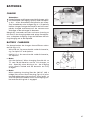
MAGNETIC BRAKE
A magnetic brake (fig. 3–6/ I) is flanged to the motor
(fig. 3–6/ J). After the driving wheels come to a still
stand, the magnetic brake instantly prevents rolling
on inclines or slopes.
FUNCTIONALITY
The disc form brake pad (fig. 3–7/ K) is located between
the flanged friction discs (fig. 3–7/ L) and the axially
moving anchor disc (fig. 3–7/ M) and is mounted swiv-
el proof through a hub to the motor shaft.
Braking condition
In a powerless state of the brake (this corresponds to a
standstill of the vehicle) a central pressure spring (un-
derneath the piston, fig. 3–8/ N) presses the brake pad
over the anchor disc against the friction disc. This pre-
vents a rotation of the motor. – Over the motor and
the connected drive the vehicle is prevented from roll-
ing.
Driving condition
With the battery current engaged the brake magnet
(fig. 3–8/ O) creates a magnetic field that pulls the an-
chor disc against the force of the central pressure disc.
– Through this the brake pad and the motor shaft con-
nected via the swivel proof hub can now move freely.
The wear of the pads can make an adjustment or re-
placement of the pads necessary.
Push mode
In the push modus the central pressure spring is me-
chanically pulled away and sets the brake pad free.
With drum brake option
The central pressure spring is pulled back by throwing
the drive-/push modus lever (fig. 3–8).
Without drum brake option
The central pressure brake is pulled back by the by the
brake hanger (fig. 3–9).
3–6
3–7
3–8
I
J
l
K
M
N
O
3–9

15
REMOVAL
– Remove the front panel.
– Without drum brake option: Set the brake lever to
push mode. Disassemble the brake bowden cable,
view chapter < magnetic brake/replacing the bow-
den cable >.
– With drum brake option: Set the selection lever (fig.
3–10/ Q) to push mode.
Removal and installation of the magnetic brake is done
with 3 hexagon socket screws (fig. 3–10/ P).
– Remove the hexagon socket screws (fig. 3–9) and
take out the magnetic housing together with the
anchor disc and adjustment pieces (fig. 3–10/ R) from
the motor.
– Pull the brake pad from the swivel proof hub on the
motor shaft.
☞ Note:
The brake pad must easily let itself be pulled off of
the star formed tappet. – Otherwise work the teeth-
ing of the brake pad with a key file until they fit
faultlessly.
– Remove the friction disc from the motor.
FITTING
The fitting is done corresponding in reverse order
fig. 3–11 and 3–12).
!
Attention:
After fitting the magnetic brake has to be readjust-
ed, view chapter < Adjustment >.
!
Attention:
If the tappet has to be removed from the motor
shaft you have to check for the correct position of
the hub when witting if back on. The hub side of
the tappet has to face away from the motor.
3–11
3–12
3–10
R
P
Q

16
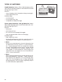
ADJUSTING
!
Attention:
Work has to be carefully carried out during the ad-
justment!
☞ Note:
The magnet brake for the E-wheelchair without
optional drum brake is done in the same fashion.
The adjustment is done with three adjustment pieces
(hollow hexagon screws) and the hexagon socket
screws stuck through them.
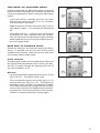
– Push a 0,2 m thick feeler gauge (fig. 3–13/ S) from
the outside between the anchor disc and brake mag-
net until it comes to rest on two adjustment pieces.
– Pull off both hexagon socket screws (fig. 3–13/ T)
that are inserted in the adjustment pieces while si-
multaneously slightly moving the feller gauge back
and forth, until the feeler gauge can just barely be
moved.
– Repeat the same procedure at another pair of ad-
justment pieces in a 120° turn.
– Repeat the adjustment several times all the way
around.
– Turn the adjustment pieces with the hexagon head
against the friction disc (fig. 3–14). – The brake mag-
net is pressed against the heads of the hexagon sock-
et screw thus countering the hexagon socket screws.
– Through the widening of the hexagon socket screws
the feeler gauge regains a little slag. With correct
fine-tuning the feeler gauge must now me move-
able slightly sucking between the anchor plate and
brake magnet.
FUNCTIONAL CHECKS
– Switch to push mode and check the free movement
of the wheelchair.
– Do a driving test.
– Watch for unusual sounds.
– Check whether the vehicle comes to a complete
standstill on the maximum permitted downhill gra-
dient (view type plate).
3–13
3–14
S
T

17
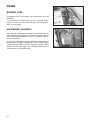
REPLACING THE BOWDEN CABLE
(Only without option drum brake)
☞ Note:
The pressure spring (fig. 3–15/ A) at the counter plate
serves for the reduction of the brake lever way and
expands the optimal area of effectiveness of the air
installation.
Removal
– Remove the counter nut (fig. 3–16/ B) from the ad-
justment screw at the counter plate. Pull back the
adjustment screw (fig. 3–16/ C) and lift the bowden
cable out through the slot.
– Unscrew the counter nut (fig. 3–17/ D) from the
adjustment screw at the brake lever. Pull back the
adjustment screw (fig. 3–17/ E) and lift the bowden
cable out through the slot.
Remove the starlock quick fasteners (fig. 3–18/ F) from
the eccentric (fig. 3–18/ G) and pull the eyelet (fig.
3–18/ H) at the end of the bowden cable from the
eccentric.
– Screw the eye screw (fig. 3–18/ I) off of the frame
and remove it together with the complete bowden
cable.
Fitting
The fitting is done analogue in reverse order.
!
Attention:
The starlock quick fastener has to be replaced un-
der all circumstances. During fitting you have to
watch for the professional assembly of the starlock
quick fastener.
☞ Note:
The eye screw has to aligned before fitting so that
the bowden cable is not bent at the adjustment
screw.
After fitting the bowden cable must be adjusted again.
3–15
3–16
3–17
3–18
A
C B
DE
H
F
G
I

18
3–19
Adjusting
The bowden cable is adjusted with the adjustment screw
at the brake lever (fig. 3–17/ E) and the adjustment
screw on the eye screw.
– Loosen the counter nuts at the counter piece and
the brake hanger.
– Adjust the bowden cable with the adjustment
screws. – To do so turn the adjustment screw against
the nut.
☞ Note:
The bowden cable is adjusted correctly if the mag-
netic brake already shows effect when the switch-
ing if the micro switch (fig. 3–19/ K) can be heard.
– Tighten the counter nuts again.
☞ Note:
After the adjustment the following must be
checked:
a) with disengaged brake (push mode) the vehicle
has to be pushed easily (bowden cable taut).
b) While the brake is engaged the vehicle may not
be moveable at all.
K

19
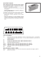
STEERING
As a standard the Optimus is fitted with electrical stee-
ring (completely mechanically operating steering op-
tional).
REPLACEMENT
For replacement the complete steering unit (fig. 4–2/
A) with tie rod (fig. 4–2/ B) is supplied.
REMOVAL
– Remove the screw (fig. 4–3/ C) out of the handle for
switching the steering from drive- to push mode
and remove the handle.
– Screw off the rear panel (view fig. 4–4).
– Unplug the cables for the taillights.
– Unlock the plug connections for the cables leading
to the steering gear. – To unlock the locking lever
press him down on the opposite side of the module.
– Screw the angle joints (fig. 4–4/ D) at the ends of
the tie rods off of the wheel suspension (fig. 4–5).
– Unscrew the steering gear from the upper and low-
er suspensions (fig. 4–6/ E) and remove them.
4–1
4–2
4–3
4–4
4–5
A
B B
D
D
C

20
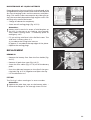
FITTING
– Set the steering gear to push mode (tie rods can be
moved freely) and check wether the disc (fig. 4–7/
F) is positioned on the steering gear as shown in fig.
4–6.
– Screw the steering gear onto the upper and lower
suspensions. – Start with upper screws.
☞ Note:
The plastic pinion (fig. 4–8/ G) of the director is tuned
from the manufacturer with a cable binder for fit-
ting. After the steering gear is screwed onto the
suspensions the cable binder has to be removed.
– Screw the angle joints onto the wheel suspensions.
– Check the alignment and adjust if necessary, view
chapter < adjusting the alignment >.
– Lay the cables for the steering and reconnect to the
power module.
– Bind the cable for the steering and the cable of the
left tail light together with a cable binder. Attach
the cable under the seat with the mounted cable
binders.
– Reconnect the plugs of the cables for the taillights
in the rear panel.
– Screw on the rear panel.
– Mount the handle and screw it on.
4–7
4–8
F
G
4–6
E
Page is loading ...
Page is loading ...
Page is loading ...
Page is loading ...
Page is loading ...
Page is loading ...
Page is loading ...
Page is loading ...
Page is loading ...
Page is loading ...
Page is loading ...
Page is loading ...
Page is loading ...
Page is loading ...
Page is loading ...
Page is loading ...
Page is loading ...
Page is loading ...
Page is loading ...
Page is loading ...
Page is loading ...
Page is loading ...
Page is loading ...
Page is loading ...
Page is loading ...
Page is loading ...
Page is loading ...
Page is loading ...
Page is loading ...
Page is loading ...
Page is loading ...
Page is loading ...
Page is loading ...
Page is loading ...
Page is loading ...
Page is loading ...
-
 1
1
-
 2
2
-
 3
3
-
 4
4
-
 5
5
-
 6
6
-
 7
7
-
 8
8
-
 9
9
-
 10
10
-
 11
11
-
 12
12
-
 13
13
-
 14
14
-
 15
15
-
 16
16
-
 17
17
-
 18
18
-
 19
19
-
 20
20
-
 21
21
-
 22
22
-
 23
23
-
 24
24
-
 25
25
-
 26
26
-
 27
27
-
 28
28
-
 29
29
-
 30
30
-
 31
31
-
 32
32
-
 33
33
-
 34
34
-
 35
35
-
 36
36
-
 37
37
-
 38
38
-
 39
39
-
 40
40
-
 41
41
-
 42
42
-
 43
43
-
 44
44
-
 45
45
-
 46
46
-
 47
47
-
 48
48
-
 49
49
-
 50
50
-
 51
51
-
 52
52
-
 53
53
-
 54
54
-
 55
55
-
 56
56


Ask a question and I''ll find the answer in the document
Finding information in a document is now easier with AI
Related papers
Other documents
-
Saxby Lighting 46896 Operating instructions
-
Invacare STORM User manual
-
Opel GT Manta 1973 User manual
-
 Abarth 500D Workshop Manual
-
-
Agria 5300 Owner's manual
-
-
Endon 91781 User manual
-
Agria Grizzly 5500 345 Owner's manual
-
Agria 5900 Owner's manual
