ZIGBEE 114729 User manual

Type
User manual

ZIGBEE 114729 is a 4-in-1 universal ZigBee LED controller that offers extensive control over your LED lights. With four different device modes (DIM, CCT, RGBW, and RGB+CCT), you can customize the lighting to suit your needs. The device can be controlled via a ZigBee controller or hub and is compatible with ZigBee remotes. It also supports self-forming ZigBee networks, allowing for easy setup and control without a coordinator. Additionally, the ZIGBEE 114729 features TouchLink commissioning, enabling direct pairing with compatible ZigBee remotes, enhancing convenience and flexibility.

ZIGBEE 114729 is a 4-in-1 universal ZigBee LED controller that offers extensive control over your LED lights. With four different device modes (DIM, CCT, RGBW, and RGB+CCT), you can customize the lighting to suit your needs. The device can be controlled via a ZigBee controller or hub and is compatible with ZigBee remotes. It also supports self-forming ZigBee networks, allowing for easy setup and control without a coordinator. Additionally, the ZIGBEE 114729 features TouchLink commissioning, enabling direct pairing with compatible ZigBee remotes, enhancing convenience and flexibility.

4 in 1 Universal ZigBee LED Controller
Input
Voltage Remarks
Output
Current
12-24VDC Constant voltage
48-96W/CH
4A/CH
Output
Power
Function introduction
Important: Read All Instructions Prior to Installation
Product Data
Size(LxWxH)
145x46.5x16mm
DO NOT install with power applied to device.
DO NOT operate the dial switches for device mode selection with power applied to device.
DO NOT expose the device to moisture.
Safety & Warnings
Operation
1.Do wiring according to connection diagram correctly, please power off and power on the device once
a device mode is selected so that the selected mode can be activated.
2.This ZigBee device is a wireless receiver that communicates with a variety of ZigBee compatible
systems. This receiver receives and is controlled by wireless radio signals from the compatible ZigBee
system.
3. Zigbee Network Pairing through Coordinator or Hub (Added to a Zigbee Network)
4. TouchLink to a Zigbee Remote
Note: 1) Directly TouchLink (both not added to a ZigBee network), each device can link with 1 remote.
2) TouchLink after both added to a ZigBee network, each device can link with max. 30 remotes.
3) For Hue Bridge & Amazon Echo Plus, add remote and device to network first then TouchLink.
4) After TouchLink, the device can be controlled by the linked remotes.
Step 1: Remove the device from previous zigbee network if it has already been added to, otherwise pairing will
fail. Please refer to the part "Factory Reset Manually".
Step 2: From your ZigBee Controller or hub interface, choose to add lighting device and enter Pairing mode as
instructed by the controller.
Step 4: Connected light will blink 5
times and then stay solid on, then the
device will appear in your controller's
menu and can be controlled through
controller or hub interface.
Step 1: Method 1: Short press “Prog” button (or re-power on the device) 4 times to start Touchlink
commissioning (lasts for 180S) immediately under any circumstances, once time out, repeat this step.
Method 2: Re-power on the device, Touchlink commissioning will start after 15S if its not added to a zigbee
network, 165S timeout. Or start immediately if its already added to a network, 180S timeout. Once timeout,
repeat the step.
Step 3: Re-power on the device to set it into network pairing mode (connected light flashes twice slowly),
network pairing mode lasts 15S (enters into touchlink mode after 15S), once timeout, repeat this step.
Step 4: There shall be indication on
the remote for successful link and
connected light will flash twice.
< 10cm
Zigbee
Remote
Step 2: Bring the remote or touch panel within 10cm of the lighting device.
Step 3: Set the remote or touch panel into Touchlink commissioning,
please refer to corresponding remote or touch panel manual to learn how.
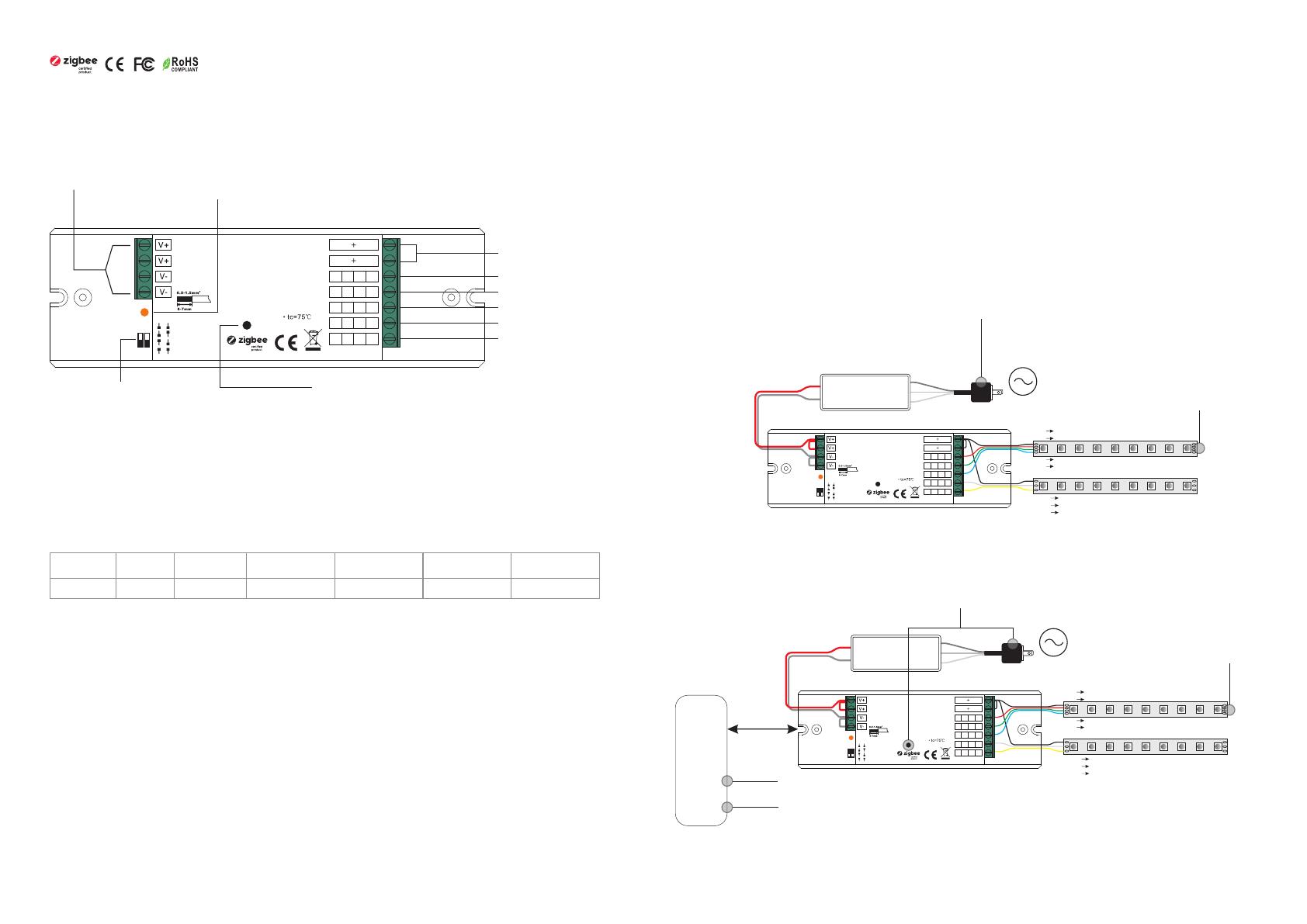
12-24VDC Power input
Common Anode Output(+)
CH1:R/R/WW/1 output(-)
CH2:G/G/CW/2 output(-)
2) Under RGB+CCT mode, RGB channels and tunable white channels are controlled separately, they can not
be turned on and controlled at the same time.
Program Key: short press to switch on/off the device,
press and hold down to increase/decrease light intensity
4 in 1 universal Zigbee LED controller based on latest ZigBee 3.0 protocol
4 different device modes DIM, CCT, RGBW and RGB+CCT in 1 controller, and selectable by dial switch
Enables to control ON/OFF, light intensity, color temperature, RGB color of connected LED lights
Can directly pair to a compatible ZigBee remote via Touchlink
Supports self-forming zigbee network without coordinator
Supports find and bind mode to bind a ZigBee remote
Supports zigbee green power and can bind max. 20 zigbee green power remotes
Compatible with universal Zigbee gateway or hub products
Compatible with universal Zigbee remotes
Waterproof grade: IP20
CH3:B/B/WW/3 output(-)
CH4:WW/W/CW/4 output(-)
CH5:CW/NC/NC/5 output(-)
Ambient
Temperature
-20℃ ~ +50
Prog.
ZigBee LED Controller
Input Voltage DC 12-24V
Output Current 4A/CH
Max Power 48-96W/CH
1 2
DC INPUT
LED OUTPUT
DIM
CCT
RGBW
RGB+CCT
1- R- R-
2- G- G-
3- B- B-
4-
WW-
WW-
WW-
W-
5-
CW-
CW-
CW-
NCNC
Ta:-20-+50
Dial switch for device mode
selection, DIM, CCT, RGBW
and RGB+CCT 4 modes are available,
factory default is RGB+CCT mode
1 2
ON
NC = No Connection
1) Under RGBW mode, W channel can only be turned on through color temperature control command (RGBW
will be identified as RGB+CCT by zigbee). Color temperature control will mix RGB channels as 1 channel white
and then make color tuning with the 4th channel white. Once turned on, the brightness of white channel will be
controlled together with RGB channels.
LED indicator, stays solid on when power on the controller, turns
off after added to a zigbee hub, indicates (same status as connected
load) when program the controller (network pairing, touchlink, factory reset)
Max. Casing
Temperature
75
AC Power
50/60Hz
L
N
G
V+
V-
OUTPUT
INPUT
12V/24V
CV PSU
RGB LED Strip
V+ V+
R- R-
G- G-
B- B-
CCT LED Strip
V+ V+
WW- WW-
CW- CW-
Max. 20A input
Prog.
ZigBee LED Co nt ro ller
Input Vo ltage D C 12- 24 V
Outpu t Curre nt 4A /C H
Max Pow er 48-9 6W/ CH
1 2
DC INPU T
LED OUT PUT
DIM
CCT
RGBW
RGB+C CT
1- R- R-
2- G- G-
3- B- B -
4-
WW-
WW-
WW-
W-
5-
CW-
CW-
CW-
NCNC
Ta:-20-+ 50
1 2
ON
5. Removed from a Zigbee Network through Coordinator or Hub Interface
From your ZigBee controller or hub interface, choose to delete or reset
the lighting device as instructed. The connected light blinks 3 times to
indicate successful reset.
6. Factory Reset Manually
Note: 1) If the device is already at factory default setting, there is no indication when factory reset again .
2) All configuration parameters will be reset after the device is reset or removed from the network.
7. Factory Reset through a Zigbee Remote (Touch Reset)
8. Find and Bind Mode
Step 2: Set the remote or touch panel (target node) into find and bind mode, and enable it
to find and bind initiator, please refer to corresponding remote or touch panel manual.
Step 3: There shall be indication on the remote or touch panel that it bind the device
successfully and can control it then.
Zigbee
Remote
Step 1: Short press “Prog.” button 3 times (Or re-power on the device (initiator node) 3 times) to start Find and Bind
mode (connected light flashes slowly) to find and bind target node, 180 seconds timeout, repeat the step.
9. Learning to a Zigbee Green Power Remote
Step 2: Set the green power
remote into Learning mode,
please refer to its manual.
Zigbee
Green Power
Remote
Step 3: Connected light will
flash twice to indicate
successful learning. Then the
remote can control the device.
Step 1: Short press “Prog.” button 4 times (Or re-power on the device 4 times) to start Learning mode
(connected light flashes twice), 180 seconds timeout, repeat the step.
Note: Each device can learn to
max. 20 zigbee green power remote.
10. Delete Learning to a Zigbee Green Power Remote
Step 2: Set the paired green power remote into
Learning mode, please refer to its manual.
Step 3: Connected light will
flash 4 times to indicate
successful deleting.
Step 1: Short press “Prog.” button 3 times (Or re-power on the device 3 times) to start delete Learning mode
(connected light flashes slowly), 180 seconds timeout, repeat the step.
Step 1: Short press “Prog.” key for 5 times continuously or re-power on the device for 5 times continuously if
the “Prog.” key is not accessible.
Step 3: Set the remote or touch panel into Touch Reset procedure to reset the
device, please refer to corresponding remote or touch panel manual to learn how.
Note: Make sure the device already added to a network, the remote added to the same one or not added to any
network.
Step 1: Re-power on the device to start TouchLink Commissioning, 180 seconds timeout, repeat this step.
Step 4: There shall be indication
on the remote and connected
light flashes 3 times for
successful reset.
< 10cm
Zigbee
Remote
Zigbee
Green Power
Remote
Step 2: Connected light flashes 3
times for successful reset.
Step 2: Bring the remote or touch panel within 10cm of the lighting device.
Note: Make sure the device and the remote or touch panel already added to the same Zigbee hub.
AC Power
50/60Hz
L
N
G
V+
V-
OUTPUT
INPUT
12V/24V
CV PSU
RGB LED Strip
V+ V+
R- R-
G- G-
B- B-
CCT LED Strip
V+ V+
WW- WW-
CW- CW-
Max. 20A input
Prog.
ZigBee LED Co nt roller
Input Vo ltage D C 12- 24 V
Outpu t Curre nt 4A /C H
Max Pow er 48-9 6W/ CH
1 2
DC INPU T
LED OUT PUT
DIM
CCT
RGBW
RGB+C CT
1- R- R-
2- G- G-
3- B- B -
4-
WW-
WW-
WW-
W-
5-
CW-
CW-
CW-
NCNC
Ta:-20-+ 50
1 2
ON
AC Power
50/60Hz
L
N
G
V+
V-
OUTPUT
INPUT
12V/24V
CV PSU
RGB LED Strip
V+ V+
R- R-
G- G-
B- B-
CCT LED Strip
V+ V+
WW- WW-
CW- CW-
Max. 20A input
Prog.
ZigBee LED Co nt ro ller
Input Vo ltage D C 12- 24 V
Outpu t Curre nt 4A /C H
Max Pow er 48-9 6W/ CH
1 2
DC INPU T
LED OUT PUT
DIM
CCT
RGBW
RGB+C CT
1- R- R-
2- G- G-
3- B- B -
4-
WW-
WW-
WW-
W-
5-
CW-
CW-
CW-
NCNC
Ta:-20-+ 50
1 2
ON
Zigbee Lighting Device
11. Setup a Zigbee Network & Add Other Devices to the Network (No Coordinator Required)
Step 2: Set another device or remote or touch panel into network pairing mode and pair to the network, refer to
their manuals.
Step 3: Pair more devices and remotes to the network as you would like, refer to their manuals.
Step 4: Bind the added devices and remotes through Touchlink so that the devices can be controlled by the
remotes, refer to their manuals.
Note: 1) Each added device can link and be controlled by max. 30 added remotes.
2) Each added remote can link and control max. 30 added devices.
13. OTA
The device supports firmware updating through OTA, and will acquire new firmware from zigbee controller or
hub every 10 minutes automatically.
Step 1: Short press “Prog.” button 4 times (Or re-power on the device 4 times) to enable the device to setup a
zigbee network (connected light flashes twice) to discover and add other devices, 180 seconds timeout, repeat
the step.
Zigbee
Remote
< 10cm TouchLink
12. ZigBee Clusters the device supports are as follows:
Input Clusters
0x0000: Basic 0x0003: Identify 0x0004: Groups 0x0005: Scenes 0x0006: On/off
0x0008: Level Control 0x0300: Color Control 0x0b05: Diagnostics
Output Clusters
0x0019: OTA
Wiring Diagram
145 mm
46.5 mm16 mm
Product Dimension
AC Power
50/60Hz
L
N
G
V+
V-
OUTPUT
INPUT
12V/24V
CV PSU
RGB LED Strip
V+ V+
R- R-
G- G-
B- B-
CCT LED Strip
V+ V+
WW- WW-
CW- CW-
AC Power
50/60Hz
L
N
G
V+
V-
OUTPUT
INPUT
12V/24V
CV PSU
AC Power
50/60Hz
L
N
G
V+
V-
OUTPUT
INPUT
12V/24V
CV PSU
CCT LED Strip
V+ V+
WW- WW-
CW- CW-
AC Power
50/60Hz
L
N
G
V+
V-
OUTPUT
INPUT
12V/24V
CV PSU
1) RGB+CCT Mode
2) RGBW Mode
3) CCT Mode
4) DIM Mode
V+ V+
R- R-
G- G-
B- B-
W- W-
CCT LED Strip
V+ V+
WW- WW-
CW- CW-
Max. 4A sin gl e co lo r LE D st ri p
V+ V+
1- V-
V+ V+
2- V-
V+ V+
3- V-
V+ V+
4- V-
V+ V+
5- V-
RGBW LED Strip
Max. 20A input
Max. 20A input
Max. 20A input
Max. 20A input
Prog.
ZigBee LED Co ntroller
Input Voltage DC 12-24V
Output Current 4A/CH
Max Power 48-96W/CH
1 2
DC INPUT
LED OUTPUT
DIM
CCT
RGBW
RGB+CCT
1- R- R-
2- G- G-
3- B- B-
4-
WW-
WW-
WW-
W-
5-
CW-
CW-
CW-
NCNC
Ta:-20- +5 0
1 2
ON
Prog.
ZigBee LED Co ntrol ler
Input Voltage D C 12 -2 4V
Output Curre nt 4 A/ CH
Max Power 48-9 6W /C H
1 2
DC INPUT
LED OUTPUT
DIM
CCT
RGBW
RGB+CCT
1- R- R-
2- G- G-
3- B- B-
4-
WW-
WW-
WW-
W-
5-
CW-
CW-
CW-
NCNC
Ta:-20- +50
1 2
ON
Prog.
ZigBee LED Co ntroller
Input Voltage DC 12-24V
Output Current 4A/CH
Max Power 48-96W/CH
1 2
DC INPUT
LED OUTPUT
DIM
CCT
RGBW
RGB+CCT
1- R- R-
2- G- G-
3- B- B -
4-
WW-
WW-
WW-
W-
5-
CW-
CW-
CW-
NCNC
Ta:-20- +5 0
1 2
ON
Prog.
ZigBee LED Co ntroller
Input Voltage DC 12-24V
Output Current 4A/CH
Max Power 48-96W/CH
1 2
DC INPUT
LED OUTPUT
DIM
CCT
RGBW
RGB+CCT
1- R- R-
2- G- G-
3- B- B-
4-
WW-
WW-
WW-
W-
5-
CW-
CW-
CW-
NCNC
Ta:-20- +5 0
1 2
ON
Note: please make sure the dial switches are at position for RGB+CCT mode as shown in above diagram.
Note: please make sure the dial switches are at position for RGBW mode as shown in above diagram.
Note: please make sure the dial switches are at position for CCT mode as shown in above diagram.
Note: please make sure the dial switches are at position for DIM mode as shown in above diagram.
AC Power
50/60Hz
L
N
G
V+
V-
OUTPUT
INPUT
12V/24V
CV PSU
RGB LED Strip
V+ V+
R- R-
G- G-
B- B-
CCT LED Strip
V+ V+
WW- WW-
CW- CW-
Max. 20A input
Prog.
ZigBee LED Co nt roller
Input Vo ltage D C 12- 24 V
Outpu t Curre nt 4A /C H
Max Pow er 48-9 6W/ CH
1 2
DC INPU T
LED OUT PUT
DIM
CCT
RGBW
RGB+C CT
1- R- R-
2- G- G-
3- B- B -
4-
WW-
WW-
WW-
W-
5-
CW-
CW-
CW-
NCNC
Ta:-20-+ 50
1 2
ON
  • Page 1 1
  • Page 2 2
  • Page 3 3

ZIGBEE 114729 User manual

Type
User manual

ZIGBEE 114729 is a 4-in-1 universal ZigBee LED controller that offers extensive control over your LED lights. With four different device modes (DIM, CCT, RGBW, and RGB+CCT), you can customize the lighting to suit your needs. The device can be controlled via a ZigBee controller or hub and is compatible with ZigBee remotes. It also supports self-forming ZigBee networks, allowing for easy setup and control without a coordinator. Additionally, the ZIGBEE 114729 features TouchLink commissioning, enabling direct pairing with compatible ZigBee remotes, enhancing convenience and flexibility.

Ask a question and I''ll find the answer in the document

Finding information in a document is now easier with AI