Page is loading ...

4
3
2
5
6
M
I
N
Scale Plate
Cover
Mounting Hole
Capillary Tube
Conduit Rubber
Grounding Screw
Terminal Screw
DIFF.
Di. Adjusting
Knob
1.7
0.63 0.59
0.14
0.27
4.48
2.4
0.19
0.55
2.12
Danfoss
060L2101
0.88
remote bulb air coil/room sensor
Danfoss
060L2107
remote bulb
air coil/room sensor
Danfoss
060L2107
remote bulb air coil/room sensor
Danfoss
060L2107
remote bulb air coil/room sensor
Danfoss
060L2107
Installation guide
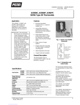
Thermostat
Type KPU
DKRCC.PI.CA0.F1.22 / 520H10107 1
060R9771
060R9771
Application
KPU 19 thermostats are used
for temperature regulation
in refrigeration, freezing, air
conditioning, ventilating and heating
systems.
KPU 19 thermostats are tted with
Single-Pole Double-Throw (SPDT)
or Single-Pole Single-Throw (SPST)
contact system.
The standard KPU 19 enclosure is rated
NEMA ~ 1.
NEMA ~ 1 is obtained when the
thermostat is mounted on a at
surface with all unused holes covered.
Type Regulating
range
[°F]
Dierential
∆T [°F]
Bulb size
[in.]
Capillary tube
length
[in.]
Max. bulb
temperature
[°F]
Ambient
temperature
[°F]
Contact
type
Reset
type
Code no.
KPU 19 -30 – 80 3.6 – 12.6
3
/
8
x 4
1
/
2
120 140
-31 – 158
SPDT Auto. 060L2150
KPU 19 -30 – 80 3.6 – 12.6
3
/
8
x 4
1
/
2
80 140
-31 – 158
SPST
(close on
temp. rise)
Auto. 060L2151
KPU 19 -30 – 80 3.6 – 12.6 -
Air coil / Room
sensor
140
-31 – 140
SPDT Auto. 060L2152
Product specication
Important
The KPU 19 thermostat is designed
only for use as a temperature
regulating operating control. It is the
responsibility of the installer to verify
that other necessary safety controls
are installed and functioning properly
as intended by the original equipment
manufacturer or system design.
Thermostat bulb types
Dimensions [in.]

A
B
Danfoss
060L2110
2 DKRCC.PI.CA0.F1.22 / 520H10107
Installation
Select an accessible location, where
the thermostat will not be subject
to damage. Mount the KPU 19 on a
bracket or on a completely at surface.
Mounting on an uneven surface may
cause incorrect thermostat operation.
Use only the mounting holes provided
at the back of the metal housing.
Wiring
Voltage [V]
Amps [A]
P.F.
cos Ø
A C
120 240
Resistive load 1 0.5 ~ 16 0.5 ~ 8
Inductive
load
Full load
Amps
0.75 0.5 ~ 16 0.5 ~ 8
Locked rotor
Amps
0.45 96 48
Do not remove cover while power
is supplied as it may cause electrical
shock.
To avoid the possibility of electric
shock and damage to equipment,
disconnect the power supply before
any wiring connections are made.
Never touch current conducting (LIVE)
parts with your ngers or with tools.
Electrical wires should be connected
through the conduit rubber or
alternatively by conduit boss.
Caution
Note:
All wiring should conform to the
National Electrical Code and to
applicable local regulations.
Use only copper wire.
Use only the terminal screws furnished
in the terminal block.
Do not exceed tightening torque of 10
lb. in. (1.18 Nm).
Do not exceed the thermostat’s
specied electrical ratings.
Do not use impact driver(shock driver).
The terminal block as well as
grounding screw are accessible after
removing the front cover.
General recommendations for
capillary tube and bulb installation:
1. Protect the capillary tube from
damage due to vibration.
a) When the thermostat unit is
mounted directly on the compressor,
the capillary tube must be secured to
the compressor so that both vibrate
together.
b) For mounting otherwise, form
surplus capillary tube into a loose loop
and secure the loop to the base on
which the thermostat is mounted.
2. Leave a little slack in the capillary
tube to help dampen vibration.
3. Avoid sharp bends (with the radius
of
1
/
2
" or less) and bending the capillary
tube at the same point several times,
as these actions can weaken the
material and increase the likelihood of
the tube cracking.
4. Bending of the capillary tube within
1.75" from soldering point with bulb is
not allowed.
5. Form and locate the capillary tube
away from sharp or abrasive objects
that might damage it.
6. For thermostats with room sensor
coils, make sure that placement allows
free airow around the coil and bulb.
At the same time, ensure that the bulb
is not exposed to drafts from doors, or
to heat radiated from the evaporator
surface. Make sure that the bulb does
not come into contact with a wall
surface. Never mount the thermostat
directly on a cold wall. Instead, mount
the unit on an insulating plate.
7. KPU 19 sensing bulb is made of
copper, copper alloy, silver solder – do
not use it for media which are harmful
for these materials .
The KPU 19 thermostat and the
sensing bulb can be mounted in any
position.
The sensing element is lled in with
liquid expansion type charging with
no limitations in terms of temperature
at switch body (TS), temperature at
sensing bulb (TB) or temperature at
capillary tube (TC). KPU 19 can operate
in all following conditions:
TS > TB; TS < TB, TS = TB.
Taking into consideration time
constant of the thermostat it is
recommended to install KPU 19
where temperature is not changing
rapidly. Fast changes of the
measured temperature will cause
thermostat measurements lags
behind actual temperature changes
in the application. Make sure to keep
temperature variable acceleration
within 3 minutes per 1.8 °F at liquid, or
within 18 minutes per 1.8 °F at air.
KPU should be installed in a place
in which harmful environmental
conditions like radiation from sun,
lamps or radiator is minimalized.
Cooling due to the extensive air ow
might aect thermostat performance
as well.
Pilot duty: 125VA; 120/240V AC
Do not make additional holes.
Locking mounting holes must be
fastened at position A as shown in
diagram to the right. Fastening at
position “B” may result in housing
deformation and KPU 19 malfunction.
It is recommended to install the
thermostat at a place where vibration
is 1G or less.
Important
Do not dent or deform the bulb of the
thermostat, as doing so could damage
the bulb and cause charge
leakage.
Do not turn any other screws except
screws on the scale plate, on the micro
switch knob and on the terminal
block.

h
For Cooling Unit
Contact function
Power Source
Cooling
Unit
For Heating Unit
Power Source
Heating
Unit
For both cooling and
Heating with Manual
Changeover Switch
Cooling
Unit
Manual
Changeover
Switch
Heating
Unit
SPDT
Example for application and wiring
Power Source
HL C
H
C
L
h
HL
C
h
HL
C
h
Arrow marking indicates a direction of switch action.
Danfoss
060L2103
Contact function
Arrow marking indicates a direction of switch action.
HC
H
C
h
h
SPST For Cooling Unit
Power Source
Cooling
Unit
Example for application and wiring
Danfoss
060L2104
4
3
2
5
6
M
I
N
LOAD
cut-out on temperature decrease
~LINE
4
3
2
5
6
M
I
N
LOAD
cut-out on temperature increase
~LINE
Danfoss
060L2108
For Cooling Unit: For Heating Unit:
2
DIFF. ADJUSTING KNOB
TEMP. DIFFERENTIAL
TEMP. DIFFERENTIAL
(°F)
14.4
12.6
10.8
9.0
7.2
5.4
3.6
1.8
MIN.
34 56
Danfoss
060L2109
DKRCC.PI.CA0.F1.22 / 520H10107 3
Wiring options
Determination of dierential
Adjustment
Note:
Adjust the thermostat to settings
specied by the manufacturer of the
controlled equipment. When checking
thermostat operation, or operating the
controlled equipment, do not exceed
the manufacturer’s temperature
ratings for the controlled equipment
or for any of its components. To avoid
inaccurate thermostat operation, do
not adjust the KPU’s pointers beyond
the highest or lowest indicator marks
on the scale plate.
Scale is indicative only. For accurate
setting please use thermometer.

4
3
2
5
6
M
I
N
Indictator
Scale Plate
Di. Indicator
DIFF.
Di. Adjusting
Knob
Danfoss
060L2106
decreasing
Dierential
Set point
Temp. rising
increasing
Co
ntact
Ac
tion
C-L OF
F
C-H O
N
C-L O
N
C-H OF
F
Danfoss
060L2105
41 ºF 50 ºF
4 DKRCC.PI.CA0.F1.22 / 520H10107
2
DIFF. ADJUSTING KNOB
TEMP. DIFFERENTIAL
TEMP. DIFFERENTIAL
(°F)
14.4
12.6
10.8
9.0
7.2
5.4
3.6
1.8
MIN.
3456
Danfoss
060L2109
Setting example (SPDT type)
Set at 41 °F for temp. decrease and
50 °F for temp. increase.
1. Set at 41 °F
Turn the scale plate to match indicator
pointer with the required value (verify
with the thermometer)
2. Set at 50 °F
Calculate the dierential between USP
and LSP (Dierential = USP – LSP;
50 °F - 41 °F = 9 °F ).
Find the proper Dierential
Adjusting Knob position from the
characteristic presented on the graph
"Determination of dierential ".
The same characteristics is shown on
the back side of the KPU 19 cover.
Dierential of 9 °F is equivalent to the
indication 4 set on the Dierential
Adjustment Knob.
3. After setting, install the cover and
supply power supply for checking
the actual switching points. Adjust
the setting if necessary as scales are
indicative only.
Enclosed accessories:
• Sensor clamp for bulb fastening.
• Blinding sticker to cover the hole
after dial knob removal. Blinding
sticker can be used only once.
• Hand knob for adjustment.
Note:
Scale values are indicative only. It is
often necessary to use a thermometer
when setting working points.
Fig. 1 Fig. 2
Upper Switch Point (USP): 50 °F
Lower Switch Point (LSP): 41 °F
© Danfoss | DCS (jmn) | 2015.05
We
, Danfoss A/S, (hereinafter referred to as “Danfoss”) truly appreciate your choosing Danfoss’ products (hereinafter referred to as “Products”).
When the P
roducts are used, this document as provided below shall be applicable except to the extent that there is anything to the contrary in any applicable estimate, agreement, catalogue, specication,
etc.
•
CONFIRMATION OF OPERATION
All customers using the P
roducts (hereinafter referred to as “Customers”) are requested to, after properly installing the Products, test the operation of the Products to conrm that all the systems in
connec
tion with the Products fully function.
In order to prevent the occurrence of bodily inju
ry, re accidents, serious damage, etc., in connection with the Customers’ machinery or equipment due to improper installation of the Products, Danfoss
k
indly requests the Customers to take the necessary safety measures by preparing safe designs such as a fail-safe design (*1) and a re spread prevention design, as well as to make the proper adjustments
f
or product reliability necessary for fault-tolerance (*2).
(*1) F
ail-safe design: Design to ensure safety in the event of any mechanical failure
(*2) F
ault-tolerance: Utilization of redundancy technology
Pe
riodic Inspection of the Products
Be sure to conrm the proper operation of the P
roducts and keep records of such operation at least once a year.
Danf
oss shall be held harmless and be indemnied by the Customers from any damages incurred due to the Customers failing to conduct the above operational procedures, provided, however, that, this
shall not apply if the damages which the C
ustomers incurred due to the defect of the Products caused by Danfoss.
•
RESTRICTIONS OF USE
T
he Products are designed and manufactured for the purpose of using them for cooling and heating and refrigerating appliances and air conditioning equipment or various industrial equipment
(hereinaf
ter referred to as “Purposes”), but are not designed and manufactured for the purpose of using the Products for any instrument or system related to human life or health purposes.
T
herefore, the use of the Products in elds related to items (1) through (3) below is not intended whatsoever. Danfoss shall be held harmless and be indemnied from any and all damages incurred by use
of the P
roducts under item (3). Also, when using the Products under the elds related to items (1) through (9) below (except for item (3), in relation to which the Products must never be used), please be
sure to notify our Danf
oss contact desk in charge of sales and obtain Danfoss’ prior written approval for such use. Danfoss shall be held harmless and be indemnied from any and all damages incurred by
use of the P
roducts in relation to these elds if the Customers do not notify Danfoss’ contact desk and obtain Danfoss’ prior written approval.
(1)In an
y eld related to nuclear power and radiation;
(2)In an
y eld related to space or seaoor equipment;
(3)In an
y equipment or device requiring a high degree of reliance on such equipment or device with respect to which it is reasonably foreseeable that failure or malfunction of the equipment or device
would either direc
tly or indirectly cause serious damage to human life, health or property;
(4)T
ransportation device (railroad, aviation, ship or vessel, vehicle equipment, etc.);
(5)Disaster-prevention or crime
-prevention device;
(6)F
acility or application directly related to medical equipment, burning appliances, electro thermal equipment, amusement rides and devices, facilities/applications associated directly with billing
, or device
using ammable uid;
(7)Equipment requiring high reliance on supply systems such as elec
tricity, gas, water, etc., in large-scale communication system, or in transportation or air trac control system;
(8)F
acilities that are to comply with regulations of governmental / public agencies or specic industries or
(9)O
ther machinery or equipment requiring a high degree of reliance and safety (excluding item(3)).
Be sure to replace the P
roducts within 5 to 10 years of delivery if no other duration of use is provided in the applicable specications or instruction manual because the conditions and environment of use
also have an impac
t on the Products.
•
SCOPE OF WARRANTY
D
ANFOSS WILL PROVIDE THE CUSTOMERS WITH REPLACEMENT OR REPAIRED PRODUCTS DELIVERED, FREE OF COST, IF THE CUSTOMERS PROVIDES TO DANFOSS WRITTEN NOTICE WITHIN BOTH (i) 12
MONTHS FROM
THE DELIVERY OF THE PRODUCT TO THE INITIAL CUSTOMERS AND (ii) 18 MONTHS FROM THE MANUFACTURED DATE OF THE PRODUCT, IN CASE THAT FAILURE OCCURS IN THE CUSTOMERS’
EQUIP
MENT USING THE PRODUCTS DUE TO A DEFECT OF THE PRODUCTS; PROVIDED, HOWEVER, THAT IN ANY EVENT THE RATIO OF THE AMOUNT THAT DANFOSS BEARS FOR THE DAMAGES INCURRED BY
T
HE FAILURE OF THE PRODUCTS OR CUSTOMERS’ EQUIPMENT SHALL NOT EXCEED THE PRICE OF THE PRODUCTS WE DELIVERED. IN ADDITION, DANFOSS SHALL BE HELD HARMLESS AND BE INDEMNIFIED
FROM ANY AND ALL D
AMAGES INCURRED WHEN THE FAILURE OF THE CUSTOMERS’ EQUIPMENT OCCURRED DUE TO ANY CAUSE SET FORTH BELOW.
(1)WHEN CA
USED BY INAPPROPRIATE HANDLING OR USE OF THE PRODUCTS BY THE CUSTOMERS (SUCH AS NOT COMPLYING WITH THE CONDITIONS, ENVIRONMENTAL SPECIFICATIONS OR CAUTIONS
INDICA
TED IN ANY APPLICABLE CATALOGUE, SPECIFICATIONS, INSTRUCTION MANUAL, ETC.);
(2)WHEN F
AILURE OCCURRED DUE TO ANY REASON OTHER THAN THE PRODUCTS;
(3)WHEN CA
USED BY MODIFICATION OR REPAIR OF THE PRODUCTS MADE BY ANYONE OTHER THAN DANFOSS OR DESIGNEE OF DANFOSS;
(4)WHEN CA
USED BY THE USE OF THE PRODUCTS IN VIOLATION OF THE ABOVE “RESTRICTIONS OF USE” OR “CONFIRMATION OF OPERATION”;
(5)WHEN SUCH F
AILURE WAS NOT REASONABLY FORESEEABLE AT THE TIME OF DANFOSS’ SHIPMENT; OR
(6)B
Y ANY OTHER CAUSE NOT ATTRIBUTABLE TO DANFOSS, SUCH AS AN ACT OF GOD, DISASTER, OR ACT OF ANY THIRD PARTY.
PLEASE NO
TE THAT THE CUSTOMERS WILL NOT BE ENTITLED TO ANY OF THE ABOVE WARRANTY IF THE CUSTOMERS PURCHASED THE PRODUCTS FROM ANY THIRD PARTY INCLUDING WITHOUT LIMITATION
B
Y INTERNET AUCTION, ETC.
/