Page is loading ...

Infrared Sensor
Operation manual
thermoMETER CX


CE-Conformity
The product complies with the following standards:
EMC: EN 61326-1
Safety Regulations: EN 61010-1:1993/ A2:1995
The product accomplishes the requirements of the EMC Directive 89/336/EEC.
Read the manual carefully before the initial start-up. The producer reserves the right to change the
herein described specifications in case of technical advance of the product.
Warranty
All components of the device have been checked and tested for perfect function in the factory. In the
unlikely event that errors should occur despite our thorough quality control, this should be reported
immediately to MICRO-EPSILON. The warranty period lasts 12 months following the day of shipment.
Defective parts, except wear parts, will be repaired or replaced free of charge within this period if you return
the device free of cost to MICRO-EPSILON.
This warranty does not apply to damage resulting from abuse of the equipment and devices, from forceful
handling or installation of the devices or from repair or modifications performed by third parties. No other
claims, except as warranted, are accepted. The terms of the purchasing contract apply in full. MICRO-
EPSILON will specifically not be responsible for eventual consequential damages.
MICRO-EPSILON always strives to supply the customers with the finest and most advanced equipment.
Development and refinement is therefore performed continuously and the right to design changes without
prior notice is accordingly reserved. For translations in other languages, the data and statements in the
German language operation manual are to be taken as authoritative.

Content
1
Description...........................................................................................................................................7
1.1 Scope of Supply ..................................................................................................................................7
1.2 Maintenance ........................................................................................................................................8
1.3 Cautions...............................................................................................................................................8
1.4 Factory Default Settings ......................................................................................................................9
2 Technical Data...................................................................................................................................10
2.1 General Specifications.......................................................................................................................10
2.2 Electrical Specifications.....................................................................................................................11
2.3 Measurement Specifications .............................................................................................................12
2.4 Optical Charts....................................................................................................................................13
2.5 CF Optics and Protective Window.....................................................................................................14
3 Installation..........................................................................................................................................16
3.1 Mechanical Installation ...................................................................................................................... 16
3.2 Air Purge Collar .................................................................................................................................17
3.3 Electrical Installation..........................................................................................................................18
3.3.1 Analog device (mA output)................................................................................................................18
3.3.2 Digital communication.......................................................................................................................18
3.3.3 Analog + Digital ................................................................................................................................20
3.3.4 Analog + Alarm .................................................................................................................................20
4 Software CompactConnect ...............................................................................................................21
4.1 Installation..........................................................................................................................................21
4.2 System requirements ........................................................................................................................21
4.3 Main Features....................................................................................................................................22

5 Digital Command Set ........................................................................................................................23
6 Basics of Infrared Thermometry ........................................................................................................ 24
7 Emissivity...........................................................................................................................................25
7.1 Definition............................................................................................................................................25
7.2 Determination of unknown Emissivities.............................................................................................26
7.3 Characteristic Emissivities.................................................................................................................27
Appendix A – Emissivity Table Metals............................................................................................................28
Appendix B – Emissivity Table Non Metals ....................................................................................................30


Description
1 Description
The sensors of the thermoMETER CX series are noncontact infrared temperature sensors.
They calculate the surface temperature based on the emitted infrared energy of objects [► Basics of
Infrared Thermometry].
The sensor housing of the thermoMETER CX is made of aluminium (IP65/ NEMA-4 rating) and contains the
complete sensor electronics. The sensor has a fixed mounted connection cable.
The CX sensors are sensitive optical systems. Please use only the thread for mechanical installation.
Avoid mechanical violence on the head – this may destroy the system (expiry of warranty).
1.1 Scope of Supply
• CX incl. connection cable, mounting nut and operators manual
thermoMETER CX 7

Description
1.2 Maintenance
Lens cleaning: Blow off loose particles using clean compressed air. The lens surface can be cleaned with a
soft, humid tissue moistened with water or a water based glass cleaner.
PLEASE NOTE: Never use cleaning compounds which contain solvents (neither for the lens nor for the
housing).
1.3 Cautions
Avoid static electricity, arc welders, and induction heaters. Keep away from very strong EMF
(electromagnetic fields). Avoid abrupt changes of the ambient temperature.
In case of problems or questions which may arise when you use the sensor, please contact our service
department. The customer service staff will support you with questions concerning the optimization of the
work with the infrared thermometer, calibration procedures or with repairs.
thermoMETER CX 8

Description
1.4 Factory Default Settings
The unit has the following presetting at time of delivery:
Temperature range: -18...500 °C/ according 4-20 mA
Emissivity: 0.950
Transmission: 1.000
Smart averaging: Active
Ambient temperature source: Head temperature
Smart Averaging means a dynamic average adaptation at high signal edges [activation via
software only].
If the unit is supplied together with the USB-kit (optional) the output will be set to digital communication
(bidirectional).
Read the manual carefully before the initial start-up. The producer reserves the right to change the herein
described specifications in case of technical advance of the product.
thermoMETER CX 9

Technical Data
2 Technical Data
2.1 General Specifications
Environmental rating IP65 (NEMA-4)
Ambient temperature -20...75 °C
Storage temperature -40...85 °C
Relative humidity 10...95 %, non condensing
Material aluminium, black anodized
Dimensions Diameter: 42 mm/ Length: 130 mm
Weight 350 g
Cable length 5 m
Cable diameter 4.3 mm
Vibration IEC 68-2-6: 3G, 11 – 200 Hz, any axis
Shock IEC 68-2-27: 50G, 11 ms, any axis
EMI 89/336/EWG
Tab. 2.1: General Specification
thermoMETER CX 10

Technical Data
2.2 Electrical Specifications
Output/ analog 4-20 mA/ scalable
Output/ serial digital
1)
uni- (burst mode) or bidirectional
Alarm output Programmable open collector output/ 0...30 VDC; 500 mA
Output impedances max. 1000 Ω loop impedance
Power supply 5...28 VDC
Tab. 2.2: Electrical Specification
1)
inverted RS232, TTL, and 9.6 kBaud
white Current loop (+)
yellow TxD (5 V)
green RxD (5 V)/ Open collector output
brown Current loop (-)/ Ground (⊥)
black Shield
thermoMETER CX 11

Technical Data
2.3 Measurement Specifications
CX-SF22-C8 CX-SF15-C8
Temperature range IR -30...900 °C (scalable via software) -30...150 °C (scalable via software)
Spectral range 8...14 μm 8...14 μm
Optical resolution 22:1 15:1
CF-lens (optional) 0,6 mm@ 10 mm 0.8 mm@ 10 mm
Accuracy
1)
±1.5 °C or ±1.5 % of reading ±1 °C oder ±1 % of reading
Repeatability
1)
±0.75 °C or ±0.75 % of reading ±0.3 °C oder ±0.3 % of reading
Temperature resolution 0.2 °C 0.025 °C
Response time 150 ms (95 % Signal)
Warm-up time 10 min
Emissivity/ Gain 0.100...1.100 (adjustable via software)
Transmissivity 0.100...1.000 (adjustable via software)
Interface (optional) USB programming interface
Signal processing Average, Peak hold, Valley hold (adjustable via software)
Software (optional) CompactConnect
Tab. 2.3: Measurement Specification
1)
at ambient temperature 23±5 °C; whichever is greater
thermoMETER CX 12

Technical Data
2.4 Optical Charts
The following optical charts show the diameter of the measuring spot in dependence on the distance
between measuring object and sensing head. The spot size refers to 90 % of the radiation energy.
The distance is always measured from the front edge of the sensor housing.
Optical chart CX (22:1)
Optical chart
CX with CF-lens (0.6 mm @ 10 mm)
thermoMETER CX 13

Technical Data
The size of the measuring object and the optical resolution of the infrared thermometer determine the
maximum distance between sensing head and measuring object.
In order to prevent measuring errors the object should fill out the field of view of the optics completely.
Consequently, the spot should at all times have at least the same size like the object or should be smaller
than that.
2.5 CF Optics and Protective Window
The optional CF-lens allows the measurement of small objects.
For protection of the sensing head optics a protective window is available. The mechanical dimensions are
equal to the CF lens.
thermoMETER CX 14

Technical Data
Fig. 2.1: CF-lens [TM-CF-CX]/ Protective window [TM-PW-CX]
If the CF-lens is used, the transmission has to be set to 0.78.
To change this value the optional USB-Kit (including CompactConnect software) is necessary.
If the protective window is used, the transmission has to be set to 0.83. To change this value the
optional USB-Kit (including CompactConnect software) is necessary.
thermoMETER CX 15

Installation
3 Installation
3.1 Mechanical Installation
The CX is equipped with a 20 UNF-2B thread and can be installed either directly via the sensor thread or
with the help of the hex nut (standard) to the mounting bracket available.
Fig. 3.1: CX – Dimensions
thermoMETER CX 16

Installation
3.2 Air Purge Collar
The lens must be kept clean at all times from dust, smoke, fumes and other contaminants in order to avoid
reading errors. These effects can be reduced by using an air purge collar. Make sure to use oil-free,
technically clean air, only.
Fig. 3.2: Air purge collar [TM-AP-CX]; Hose connection: 6x8 mm
The needed amount of air (approx. 2...10 l/ min.) depends on the application and the installation
conditions on-site.
thermoMETER CX 17

Installation
3.3 Electrical Installation
3.3.1 Analog device (mA output)
The maximum loop impedance is 1000 Ω.
3.3.2 Digital communication
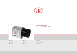
For a digital communication the optional USB programming kit is required. Please connect each wire of the
USB adapter cable with the same coloured wire of the sensor cable by using the terminal block. Press with
a screw driver as shown in the picture to loose a contact.
thermoMETER CX 18

Installation
USB-Kit: USB
programming adaptor incl.
terminal block and
software CD
[
TM-
US
BK-
C
X
]
Fig. 3.3: USB-Kit
The sensor is offering two ways of digital communication:
• bidirectional communication (sending and receiving data)
• unidirectional communication (burst mode – the sensor is sending data only)
thermoMETER CX 19

Installation
3.3.3 Analog + Digital
The CX is able to work in the digital mode and simultaneously as analog device (4-20 mA).
In this case the sensor will be powered by the USB interface (5 V).
3.3.4 Analog + Alarm
The alarm output (open collector output) can control an external relay. In addition the analog output can be
used simultaneously.
thermoMETER CX 20
/