BeefEater BS19640 User manual
- Category
- Barbecues & grills
- Type
- User manual

FOR OUTDOOR USE ONLY AUSTRALIA / NEW ZEALAND
Assembly and Operating Instructions
SIGNATURE
SERIES
PLUS, S-3000E, S-3000S
BALCONY

2 CONTENTS
Important safety instructions ��������������������������������������������������������3
Gas cylinder safety ������������������������������������������������������������������������4
Gas leak test procedure ����������������������������������������������������������������4
Tools required ��������������������������������������������������������������������������������5
Assembly instructions �������������������������������������������������������������������6
Installation instructions ����������������������������������������������������������������9
Assembly and gas connection instructions for side burner ������10
Assembly instructions for trolley ������������������������������������������������11
Operating instructions ����������������������������������������������������������������18
Hood assembly instructions��������������������������������������������������������22
Getting the most from your roasting hood ���������������������������������23
Help guide ������������������������������������������������������������������������������������25
Care and maintenance ����������������������������������������������������������������27
Locating your barbecue and side burner �����������������������������������31
Outdoor installation instructions ����������������������������������������������� 32
Specifications ����������������������������������������������������������������������������� 33
Notes ������������������������������������������������������������������������������������������� 34
Warranty ��������������������������������������������������������������������������������������35
Please read the user manual carefully and store in a handy
place for later reference�
The symbols you will see in this booklet have these
meanings:
WARNING
WARNING
This symbol indicates information concerning your
personal safety.
WARNING
CAUTION
This symbol indicates information on how to avoid
damaging the appliance.
TIPS & INFORMATION
IMPORTANT
This symbol indicates tips and information about use
of the appliance.
ENVIRONMENTAL TIPS
ENVIRONMENT
This symbol indicates tips and information about
economical and ecological use of the appliance.
Dear customer,
Congratulations and thank you for choosing our barbecue�
We are sure you will find it a pleasure to use� Before you use
the barbecue, we recommend that you read through the
relevant sections of this manual, which provide a description
of your appliance and its functions�
To avoid the risks that are always present when you use
an appliance, it is important that the appliance is installed
correctly and that you read the safety instructions carefully to
avoid misuse and hazards�
We recommend that you keep this instruction booklet
for future reference and pass it on to any future owners�
After unpacking the appliance, please check it is not
damaged� If in doubt, do not use the appliance but contact
your local customer care centre�
This appliance complies with requirements of Australian
Standards AS4557�
CONDITIONS OF USE
These important notes apply to your appliance
• This appliance MUST be installed and serviced only
by a qualified licensed person�
• This product is intended for personal, domestic or
household use only, not commercial use�
• This product is intended for outdoor use only�
• This product must be installed, operated and maintained
as per the instructions�
• Ventilation holes in the unit must not be obscured by the
installation�
Please ensure you read the instruction manual fully
before you call for service, or a full service fee could
be applicable.
Record model and serial number here:
Model number: �������������������������������������������������������������������������������
Serial number: ��������������������������������������������������������������������������������
PNC: ������������������������������������������������������������������������������������������������
CONTENTSCONGRATULATIONS

3SAFETY
Please read the user manual carefully and store in a handy
place for later reference�
TIPS & INFORMATION
IMPORTANT
Important – check for any damages or marks
If you find the barbecue is damaged or marked, you must
report it within 7 days if you wish to claim for damage/
marks under the manufacturer’s warranty. This does not
affect your statutory rights.
ENVIRONMENTAL TIPS
ENVIRONMENT
Information on disposal for users
• Most of the packing materials are recyclable. Please
dispose of those materials through your local recycling
depot or by placing them in appropriate collection
containers.
• If you wish to discard this product, please contact
your local authorities and ask for the correct method
of disposal.
WARNING
WARNING
This appliance must be serviced only by a qualified
licensed person.
Improper installation, adjustment, alteration or
maintenance can cause injury or property damage.
Please contact your nearest Electrolux Service
Department for additional information or assistance
for an approved installer.
NOTE: This manual must remain with the owner for
future reference�
WARNING
WARNING
• Do not lean over barbecue when lighting.
• Do not leave the barbecue unattended when alight.
• Do not delay lighting once the gas has been turned on.
• Do not store or use aerosol cans in the vicinity of
the barbecue.
• Do not store flammable liquids in the vicinity of the
barbecue.
• Do not use caustic or abrasive based cleaners on
the barbecue.
• Do not attempt to dismantle or adjust the control
valves.
• Do not attempt to dismantle or adjust the regulator.
• Do not test for leaks with a naked flame.
• Do not modify the construction of this appliance or
modify the injector orifice size.
• Do not obstruct any ventilation of the barbecue.
• Do not allow children to operate or play near the
barbecue.
WARNING
CAUTION
Barbecue is supplied set for LPG. A Natural Gas Conversion
kit is available. A Universal LPG and propane conversion kit
is included if required. Conversion of this unit to Universal
LPG or propane must be carried out by a qualified licensed
person and a Certificate of Compliance must be issued
to the owner at the completion of the installation and
conversion.
IMPORTANT SAFETY INSTRUCTIONS

4 GAS CYLINDER SAFETY
GAS CYLINDER SAFETY GAS LEAK TEST PROCEDURE
Gas Cylinder Safety Information
This appliance is designed to be used with a gas cylinder not
exceeding 9KG (20lbs) capacity�
The Gas cylinder must be constructed and marked in
accordance with specifications for LP Gas Cylinders of
the:(USA) U�S� Dept� of Transportation (DOT) or the National
Standard of Canada, CAN/CSA - B339, Cylinders, Spheres or
Tubes for the transportation of dangerous goods�
The gas cylinder supply valve must be turned off when
the appliance is not in use� Gas cylinders must be stored
outdoors, out of reach of children and must not be stored in
a building, garage or any other enclosed area�
The gas cylinder used must incorporate a safety collar to
protect the valve assembly�
IMPORTANT!
When disconnecting and removing the gas cylinder for the
purpose of refilling, always observe the following procedure�
Ensure that all gas control valves on the appliance and the
gas cylinder are turned off before disconnecting the gas line
from the cylinder�
Do not smoke or use a naked flame near the appliance or
gas cylinder while disconnecting the gas line between the
appliance and gas cylinder�
Remove the gas cylinder from the enclosure before
disconnecting the gas line from the appliance�
Tighten all connections before placing the gas cylinder back
in its enclosure�
The Gas Leak Testing Procedure should be conducted every
time the gas cylinder is refilled and reconnected to the
appliance - before using the appliance�
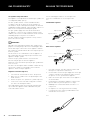
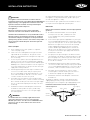
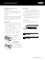
Regulator connection (Fig 1 & 2)
1� Check that all control knobs are in the ‘Off’ position�
2� Make sure the cylinder valve is off by turning the valve
knob clockwise�
3� Remove the protective cap from the cylinder if present�
4� Leak test the connection with a soapy water solution
(See Gas Leak Testing Procedure)
Hose and regulator replacement must be a genuine part
specified for this appliance and is obtainable from your
nearest BeefEater stockist�
Use the following procedure to check for gas leaks�
Never use a naked flame to check for gas leaks�
FIG 1
Standard POL regulator
FIG 2
Quick connect regulator
1� In a small container, mix up a solution of water and
detergent or soap� Mix the solution well�
2� For LPG make sure that the gas supply valve on the gas
cylinder is turned on� For Natural gas make sure that
the gas line is correctly fitted to the appliance�
3� Make sure that the gas control valves on the appliance
are all turned off�
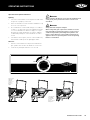
4� Using a brush or spray bottle apply the solution to the
gas line and each join in the gas line� See Fig 3�
5� Bubbling of the solution will indicate that there is a
leak present�
6� Re-tighten or re-seal any joints that are leaking�
7� If a leak persists then contact your distributor or the
manufacturer for assistance�
FIG 3
Gas shutoff valve
Gas shutoff valve
Bleeder valve screw
Bleeder valve screw
Protector cap
Protector cap
Gas cylinder
Gas cylinder
Regulator and hose
Regulator and hose
Tighten in this direction
Tighten in this direction

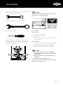
5TOOLS
TOOLS REQUIRED
You will need the following tools to assemble your barbecue�
10mm Spanner (wrench) all body nuts
19mm Spanner (wrench) for gas inlet connection
Phillips Head Screwdriver
NOTE: Always use the correct size spanner (wrench) to
tighten gas fittings� Ensure that all gas fittings are spanner
tightened and then leak tested before continuing with
operation of the appliance�
FIG 4
IMPORTANT!
Always check the gas label on the appliance to ensure that
you have the correct gas configuration.
FIG 5
For Your Safety
If you smell gas:
1� Shut off gas to the appliance�
2� Extinguish any open flame�
3� Open lid�
4� If odour continues, immediately call your gas supplier or
your fire department�
For Your Safety
1� Do not store or use gasoline or other flammable vapours
or liquids in the vicinity of this or any other appliance�
2� An LPG cylinder not connected for use shall not be
stored in the vicinity of this or any other appliance�
IMPORTANT!
• The cylinder supply system must be arranged for
vapour withdrawal. This normally means the cylinder
must be upright.
• Do not store a spare LP-gas cylinder under or near
this appliance.
• Never fill the cylinder beyond 80% full.
If these directions are not followed exactly, a fire causing
death or serious injury may occur.

6
ASSEMBLY INSTRUCTIONS
ASSEMBLY INSTRUCTIONS
Assembly notes
Before any assembly or installation is attempted it is
important that you check for damage or missing parts�
Your dealer or the manufacturer must be notified of any
problems immediately before proceeding�
The main frame of the barbecue has been factory assembled
requiring only the following simple steps for completion�
Check the “Gas Type “ label attached to barbecue and side
burner to be certain this gas type is the one required for your
use eg� Propane / LPG or Natural Gas� See Fig 5�
Trolleys, roasting hoods and side burners are optional so
read this manual in conjunction with the manual that comes
with each accessory before attaching any other components�
Attach the roasting hood last of all�
Assembly procedure
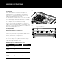
Heat reflectors, burners and vaporisers
The modular vaporiser grid system has been designed to
maximise the performance of your BeefEater barbecue the
reflectors fit between each burner� They reflect heat from the
burners, upwards to the cooking surfaces�
The vaporizers are designed to vaporise fats and juices from
the meat� One vaporiser is fitted over each burner that is
located under the grill� The vaporisers reduce flare-ups and
help to add that great barbecue flavour�
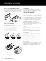
How many vaporisers and reflectors are there?
MODEL VAPORISER REFLECTOR
2 BNR 2 1
3 BNR 2 2
4 BNR 3 3
5 BNR 3 4
FIG 6
FIG 7
Upper slots for vaporisers
Lower slots for heat reflectors

7ASSEMBLY INSTRUCTIONS
ASSEMBLY INSTRUCTIONS
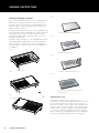
Fitting the heat reflectors
Completely remove all of the plastic film from the reflectors�
The tabbed ends of the heat reflectors face forward to the
front of the barbecue frame� The tabs fit into the slots in the
front end of the barbecue (behind the control fascia)� Key
the tabs of the vaporisers into the lower slots (between the
burners)� Key the tabs of each reflector into the slots� If slots
are partially covered with enamel, work the tabs until the
enamel clears� See Fig 8�
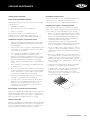
Fitting the burners
Remove the retaining clips from the burners, then fit the
burners - open end first, over the brass stem of the control
valves at the front of the barbecue, allowing the rear
burner lug to locate into the cross-lighting channel and
corresponding hole in the support panel at the rear or the
barbecue� To secure burners fit retaining clips (“R” shape)
into burner lugs� See Fig 9 & 10�
FIG 8
FIG 9
Fitting the vaporisers
Remove the protective plastic film from each vaporiser and
then fit the vaporisers to the barbecue� The tabbed ends
of the vaporisers face forward to the front of the barbecue
frame� The tabs fit into the slots in the front end of the
barbecue (behind the control fascia)� Key the tabs of the
vaporisers into the upper slots� The vaporisers should be
fitted to the same side of the barbecue to which the grill is
to be placed� (They will not work if fitted under the plate)� If
slots are partially covered with enamel, work the tabs until
the enamel clears� See Fig 11 & 12�
FIG 10
FIG 11

8
ASSEMBLY INSTRUCTIONS
ASSEMBLY INSTRUCTIONS
Fitting the cooking plates and grills
We recommend fitting the plate to the left-hand side of the
barbecue frame (with the drain hole to the extreme left)�
The grill or grills can be fitted to the right hand side of the
barbecue frame� Grills must always be positioned over the
Vaporizer grids� See Fig 13�
BeefEater 2, 3 & 4 burner barbecues come standard with 1/2
plate and 1/2 grill and are approved for use with a maximum
of 50% plate over the entire cooking area� Do not replace
the grill with another plate as this will cause severe heat
damage to the appliance�
BeefEater 5 burner barbecues come standard with 1/3 plate
and 2/3 grill and are approved for use with a maximum of
2/3 plate� Do not cover the entire surface of the barbecue
frame with plates as this will cause severe heat damage to
the appliance�
FIG 12
FIG 13
FIG 14
FIG 15
FIG 16
FIG 17
FIG 18
Fitting the grease tray
Neatly line the drip tray with a couple of sheets of
aluminium foil� Cut the foil to shape and make sure that the
foil sits on the bottom of the tray or corners of the foil so
that it does not foul in the tray sliders on the bottom of the
barbecue frame� The foil will aid in clean up & help reduce
leakage� Fill the tray with a 6mm (1/4”) layer of dry sand
or other non-combustible absorbent material to absorb
grease� Change the foil and absorbent material regularly to
reduce the likelihood of a drip tray fire� See Fig 15-18�
Rear of barbecue
Neatly line the drip tray with aluminium foil
Add absorbent material
Spread the absorbent material out evenly
Ensure that the absorbent material is not more
than 6mm deep�
Rear of barbecue
Grease drain hole

9
INSTALLATION INSTRUCTIONS
INSTALLATION INSTRUCTIONS
IMPORTANT
This appliance must be installed in accordance with the
installation requirements of the LOCAL GAS and ELECTRICITY
supply authority, or the appropriate installation code issued
by the A.G.A. and the A.L.P.G.A. Servicing should only be
carried out by an authorised person.
This appliance:
Must have a minimum clearance from combustible
materials of all sides of the barbecue of 450 mm (18”).
Should not be installed under or on any combustible surface.
Must be tested for safe and proper operation on completion
of installation and prior to leaving the site. Keep ventilation
opening of any cylinder enclosure clear and free of any debris.
Check ‘Gas Type’ label & data plate attached to right side
of barbecue.
LP Gas / Propane
A� Fit the regulator to the LPG cylinder� See regulator
connection page 2, Fig 1�
B� Connect the hose and regulator to the gas inlet at the
right hand side of the barbecue� The gas inlet of the
barbecue is 3/8 SAE male flare fitting� Do not subject the
hose to twisting�
C� Secure all joints spanner (wrench) tight but do not over-
tighten� Check for leaks after turning on gas supply by
brushing onto all joints a solution of water and detergent�
Bubbling of the solution will indicate leaks� Re-tighten or
reseal any leaking joints� If leaks persist turn off the gas
supply and consult your dealer�
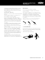
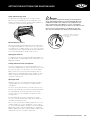
D� Following operating instructions light each burner and
check for a clear blue flame with just a tip of yellow�
Excess yellow tipping can be adjusted using the screw
on the side of the burner� Turn the screw in a counter
clockwise rotation to remove the yellow�
E� For mobile trolley installations, when using a flexible
hose to a fixed fuel source, a chain or similar restraining
device must be fitted to prevent strain on the gas supply
hose or accidental uncoupling� Do not subject the hose
to twisting�
F� For build-in situations allow adequate ventilation for
the barbecue and cylinder� Keep the cylinder away
from heat and allow clear access to the gas supply
hose and regulator�
WARNING
WARNING
The flexible PVC hose assembly supplied must not be
exposed to temperatures in excess of 60°C (140°F).
DO NOT expose to the sun’s direct heat and DO NOT allow
the hose to come in contact with the hot surface of the
barbecue body.
Recommended minimum LPG cylinder capacity for use with
this appliance is 4kg� Maximum LPG cylinder capacity for
use with this appliance is 10kg�
Do not install the gas cylinder beneath the barbecue unless
in conjunction with an approved separator panel�
Natural Gas
(Natural Gas installation should be carried out by a qualified
gas fitter).
A� BeefEater Natural Gas barbecues are designed
for low pressure (4�0” WC, 1�00KPa) to be used
as freestanding units, trolley mounted, or built
into brickwork�
B� Fit the natural gas regulator supplied directly to the gas
inlet via hard plumbing and install a shutoff valve within
easy reach in the gas line� Secure all joints spanner tight
but do not over-tighten� Check for leaks after turning
on gas supply by brushing onto all joints a solution
of water and detergent� Bubbling of the solution will
indicate leaks� Re-tighten or reseal any leaking joints�
If leaks persist turn off the gas supply and consult the
manufacturer or dealer�
C� Test gas pressure by removing the last burner from the
left hand side of the barbecue and attaching a hose and
pressure gauge to the end of the gas valve� Turn on two
burners and check the pressure� Inlet pressure should
be 4�0” WC or 1�00 KPa�
D� Following operating instructions light each burner and
check for a clear blue flame with just a tip of yellow� Avoid
excess yellow tipping by adjusting the screw on the side of
the burner, counter-clockwise rotation removes yellow�
E� For mobile trolley installations a chain or similar
restraining device must be fitted to prevent strain or
accidental uncoupling of the gas supply line�
D� For build-in situations allow adequate ventilation for
the barbecue�
The barbecue appliance must be isolated from the gas
supply piping system by closing its manual shutoff valve
during any pressure testing of the gas supply piping system�
Installation to Natural Gas must be carried out by an
authorised person.
Yellow tipping
Right Wrong
Yellow tipping
Light blue
Dark blue
Dark blue
Light blue

10
Converting the unit to natural gas
1� Turn off the gas supply valve on the gas cylinder� Ensure
that all gas controls on the BBQ are in the OFF position�
2� Disconnect the hose and regulator from the gas
cylinder and disconnect the gas hose from the barbecue
gas inlet using a 19mm open-ended spanner / wrench�
3� Open hood and remove all cooking plates, grills and
vaporisers from the BBQ�
4� Remove the ‘R’ shaped locking clips that hold each
burner in place and remove all burners from the
barbecue� This needs to be done at the rear of the BBQ�
5� The gas injectors (also known as jets or nozzles) for
each burner are located within deep pockets at the rear
of the BBQ�
6� Remove each gas injector from the end of each jet
holder using a 6mm socket spanner/ wrench, turning
gently in a counter clockwise direction� Be careful not
to block the orifice at the end of the valve where the gas
injector is fitted and do not remove any of the thread
sealing compound from the orifice where the injector is
located�
7� Check the identification mark stamped on the Hex Head
of the injector to confirm that it is the correct size (NG:
2�10mm)� Screw correct Jets back into place�
8� When fitting the NG gas injectors to the end of the jet
holder be sure to seat the injector correctly on the
thread before turning it in a clockwise direction until it
is seated firmly in place� Do not over-tighten�
9� Replace all parts into position in the BBQ
10� Refit the burners and secure with the locking clips that
hold each burner is position� Replace the vaporisers,
grills and cooking plates� Note: Check the operation
of each burner- it may be necessary to open the air-
mixture screw (located at the burner venturi) a couple of
turns to get the correct flame�
11� Replace the LPG gas type label with the natural gas
label supplied� 12� Leak test using same procedure for
LPG, as detailed on page 4�
12� Connect the natural gas hose and regulator (where
applicable) to the gas inlet on the barbecue� Tighten
firmly but do not over tighten� Connect gas regulator
to gas source line� Perform leak test using same
procedure as for LPG�
ASSEMBLY AND GAS CONNECTION INSTRUCTIONS FOR SIDE BURNER
ASSEMBLY AND GAS CONNECTION INSTRUCTIONS FOR SIDE BURNER
Turn down adjustment
When converting to natural gas the turndown setting will
need to be adjusted to give a satisfactory flame on low
setting on each burner�
• Remove knobs from valve shafts� For ignition valves
the low flame adjustment screw is located on the lower
right hand corner of the front of the valve body�
High
Low
Off
• Using a flat bladed screwdriver, turndown adjustment
screw should be fully inserted and then rotated
• For non-igntion valves the screw is located inside the
knob spindle� Use a 2�5mm wide flat blade screwdriver
full inserted and make a ¾ turn counter clockwise�
Low
• Repeat for other valve�
• Following of the gas and leak testing as per previous
steps, light both burners and set to high�
• One burner at a time turn the valve shaft to lowest
setting, observe the flame to ensure a small steady
flame in achieved�
• Turn off burners and replace control knobs, ensuring
the knob is in the correct orientation when valve is in
“OFF” position�
Fixed Installation - Portable LP Gas/Propane.
BeefEater LPG/propane barbecues are designed to operate
at 2�75Kpa (11”WC)�
Connect the gas supply line to the barbecue inlet located on
the right side of the appliance using either hard plumbing,
or a flexible hose connected to a bayonet point, also known
as a quick connect fitting�Refer to AS 5601 or your local
installation code for pipe sizing details�Secure all joints
spanner (wrench) tight but do not over-tighten�
Aeration Screw Adjustment

11ASSEMBLY INSTRUCTIONS FOR TROLLEY
ASSEMBLY INSTRUCTIONS
FOR TROLLEY
Test gas pressure by removing the last burner from the
left hand side of the barbecue and attaching a hose and
pressure gauge to the end of the gas valve�Turn on 2
burners and check the pressure�Inlet pressure should be
11�0” WC or 2�75 kPa�
Fixed Installation - Natural Gas
(Natural Gas installation should be carried out by a qualified
gas fitter)�
BeefEater Natural Gas barbecues are designed as low-
pressure appliances (4�0” WC, 1�00KPa)�
Fit the natural gas regulator supplied directly to the
barbecue inlet located on the right side of the appliance
using either hard plumbing, or a flexible hose connected to
a bayonet point, also known as a quick connect fitting�Refer
to AS 5601 or your local installation code for pipe sizing
details�Secure all joints spanner (wrench) tight but do not
over-tighten�
Test gas pressure by removing the last burner from the
left hand side of the barbecue and attaching a hose and
pressure gauge to the end of the gas valve�Turn on 2
burners and check the pressure�Inlet pressure should be
4�0” WC or 1�00 kPa�
Australia only (applies to all gas types) : Where a mobile
appliance is to be connected to a fixed gas supply via a
flexible hose connection, a retaining tether of adequate
strength shall be fixed to the appliance and be suitable to
be fixed to the wall within 50mm of each connection
point� The length of the tether shall not exceed 80% of the
length of the hose assembly� In this way, if the barbecue
is accidentally moved, the chain stops the barbecue from
stretching the hose�
The barbecue appliance must be isolated from the gas
supply piping system by closing its manual shutoff valve
during any pressure testing of the gas supply piping system�
Before You Start
Note the tools you will need before you begin�
Check for damaged or missing parts, and consult your
retailer if necessary�
Many components and panels are covered with a protective
sheet of plastic� You will need to remove this plastic covering
from all surfaces, especially where two panels join� It is
a good idea to leave some plastic on the panels during
assembly to protect the stainless steel during the assembly
process� Ensure however that all plastic covering is removed
on completion�
Always assemble on a clean, smooth, flat working surface
that will not scratch the surface of the stainless steel�
Allen Key Adjustable
spanner/
wrench
Phillips head
screwdriver
1) Fit The Fixed Castors
Fit the fixed castors into the holes in the bottom of the base�
At this step, use only two Allen head screws, washers and
nuts for each castor in the positions shown� The two outside
screws will be put on in step 3�
Spanner/wrench tighten immediately�
Note lip
ends here

12 ASSEMBLY INSTRUCTIONS FOR TROLLEY
2) Fit The Rotating Castors
Fit the rotating castors into the holes in the bottom of the
base� Again, use only two Allen head screws, washers and
nuts for each castor in the positions shown�
Spanner/wrench tighten immediately�
3) Fit The Right And Left Side Panels
Use 5 Allen head screws, washers and nuts on each panel�
You may find it easier to lay the cart on its side for this step�
Only hand tighten at this stage - You will wrench/spanner
tighten at a later step�
The right side has holes
for the gas hose
ASSEMBLY INSTRUCTIONS FOR TROLLEY
4) Fit The Magnets To The Cross Brace
Hold the cross brace so the folded tabs are facing towards
you� Push the magnets into place so the magnetic side is
facing you�
Steel is folded up
towards you
5) Fit The Front Cross Brace
Use 4 Allen head screws, washers and nuts� Ensure the
magnets are towards the bottom and the folded tabs are
facing outwards�
The cross brace “wraps around” the side panels, to bring
them closer together, as shown in the inset�
Hand tighten only at this stage�

6) Fit The Lower Back Panel
Both back panels are identical�
Screw one of the back panels to the base and side panels
using 7 Allen head screws, washers and nuts�
Hand tighten only at this stage�
7) Fit The Upper Back Panel
Screw the other back panel to the side panels� Use only
one Allen head screw, washer and nut on each side, in the
uppermost hole�
Hand tighten only at this stage�
8) Fit The Towel Rack
If you purchased the optional towel rack, you can attach it to
either the right or left side panel�
First, unscrew and remove the plastic end caps from the
towel rack� Then, using 2 countersunk screws, washers and
nuts, attach the towel rack to the side panel�
You may need to slide the towel rails out of the way to
access the screw holes�
Tighten immediately�
13ASSEMBLY INSTRUCTIONS FOR TROLLEY
9) Fit The Left Side Shelf
Use 4 Allen head screws, nuts and washers� Get in
underneath the side shelf and screw the shelf to the side
panel� The screws go into the slotted holes as shown�
If you have a second side shelf you should fit it at this point,
only for lower shelves, the screws go in the round holes at
the side�
All side shelves should be tightened immediately�
10) Fit The Top Enclosure Panel
The front of the enclosure panel sits neatly on the front
cross brace� The back of the panel screws into both the
upper back panel and the side panel� Use two Allen head
screws, washers and nuts�
Hand tighten only at this stage�
ASSEMBLY INSTRUCTIONS FOR TROLLEY
You can fit the towel rack to either
the left or right side panel.

14 ASSEMBLY INSTRUCTIONS FOR TROLLEY
11) Fit The Infill Panel (5 burner models only)
5 burner models require an infill panel between the two
doors� Use 4 Allen head screws, washers and nuts to secure
the panel between the front cross brace and the base plate�
Hand tighten only at this stage�
12) Fit The Doors
Support the door rod from underneath, slip the top of the
rod into the hole in the cross brace, and allow the bottom of
the rod to fall into the hole in the base plate�
You should now wrench/spanner tighten the infill panel if
one has been fitted�
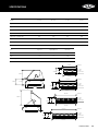
Isometric view
Scale: 1:5
Isometric view
Scale: 1:5
ASSEMBLY INSTRUCTIONS FOR TROLLEY
13) Fit The Internal Condiment Racks
These fit directly into the key holes on the inside of
the doors�
Isometric view
Scale: 1:5
14) Fit The Storage Racks
If you purchased any optional storage racks, they slide easily
into the holes on the right or left side panel�
Isometric view
Scale: 1:5
15) Fit The Hose Protector
Squeeze the rubber hose protector and fit it into one of the
holes in the side panel� You have a choice as to which hole
you use:
If you intend to use bottled gas, you should use the hole in
the side as shown�
If you will be using piped gas, then your gas plumber may
prefer it at the rear of the barbecue�
Isometric view
Scale: 1:5

15ASSEMBLY INSTRUCTIONS FOR TROLLEY
ASSEMBLY INSTRUCTIONS FOR TROLLEY
16) Fit The Cylinder Bracket
This slips into the slot on the right side panel, on either the
inside or the outside of the cart� This allows a cylinder to
be placed on the outside of the cart, or inside the cabinet
enclosure�
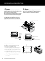
17) Lower The Barbecue Into The Cart
The gas hose and regulator assembly is factory fitted to
the primary gas inlet� For mobile units some configurations
will require the disconnection of this gas hose to pass
through holes provided in trolley panels� Once hoses are
reconnected they must be leak checked
Refer below for optional side burner connection
configuration�
You will need to tease the side panels apart slightly to be
able to put the barbecue into place� Make sure the barbecue
is pushed back against the rear edge of the cart, and the
front of the barbecue is flush with the front of the cart�
You do not need to screw anything in at this stage� That is
done in the next two steps�
18) Fit The Optional Side Burner
If you purchased a side burner, the side burner must go on
the right side of the barbecue� Use 4 Allen head screws,
washers and nuts� The screws go through the inside of the
barbecue and help to secure it�
Check The Gas Type
Before beginning installation or assembly, check that the
gas type which the barbecue and side burner are designed
for is correct for the gas available to you� In most countries
the choices are natural gas or LPG/propane� You will find
the gas type label on the side of your barbecue� If your
barbecue uses the incorrect gas type, or if you are unsure,
consult your dealer before going any further� Using the
wrong type of gas for a barbecue is extremely dangerous�
Natural Gas Conversion: Most newly purchased barbecues
are made for LPG/propane� A natural gas conversion kit is
available to allow your barbecue to run on natural gas�
NOTE: gas conversion must be carried out by an authorised
BeefEater service agent or licensed gas fitter�

Connection to Barbecue
Ensure all gas controls on the barbecue and side burner are
set to OFF�
Take the connector hose that came with the side burner�
Connect one end to the inlet of the barbecue� Connect the
other end to the left side gas connection point of the side
burner�
If your barbecue came with a cabinet trolley/ cart, your
connector hose should already be attached to the barbecue
inlet (as indicated by the separate cart instructions)� In this
case, simply pass the free end of the hose through the hose
access hole in the side of the cart prior to connecting to the
side burner inlet�
Connection To Gas Supply
Ensure all gas controls on the barbecue and side burner are
set to OFF�
Attach the gas supply hose to the right side inlet of the side
burner�
If the gas supply hose is not already attached to the gas
supply, then attach it now�
If your barbecue came with a cabinet trolley/cart, your gas
supply hose may already be attached to a portable gas
cylinder located inside the cabinet� In this case, simply pass
the free end of the hose through the hose access hole in the
side of the cart prior to connecting to the side burner inlet�
Using two spanners, tighten all gas connections� Do not
overtighten�
16 ASSEMBLY INSTRUCTIONS FOR TROLLEY
ASSEMBLY INSTRUCTIONS FOR TROLLEY
NATURAL
GAS
REFER TO LOCAL
GAS AUTHORITY F OR CONFIRMATION OF GAS
TY FIEP DNI OU TB
LPG
PROPANE
GAS
REFER TO LOCAL
GAS AUTHORITY FOR CONFIRMATION OF GAS
TY TBUODNIFIEP
hose access
hole
Assembly
Attach your side burner to your barbecue trolley as explained
in the separate barbecue/trolley instructions�
Attach The Trivet
Place the trivet on the body of the side burner� The small
notches underneath the trivet should sit neatly in the holes
in the steel, as shown�
Temporarily Remove The Drip Plate
In order to properly connect the hoses to the side burner, you
may find it easier to remove the drip plate from underneath
the side burner�
Simply undo the screw at the front of the side burner as
shown, and then ease the rear drip plate tabs from the side
burner body�
You now have clear access to the side burner inlets�
hose
access
hole
side burner gas
connection
LPG gas
supply hose
connector hose

Replace The Drip Plate
Push the rear drip plate tabs back into the slots at the back
of the side burner body, and secure the front of the drip plate
with the screw removed earlier�
Secure All Joints And Leak Test
The gas leak testing procedure should be conducted every
time a gas cylinder is refilled and reconnected to the
appliance, or after any new gas connection is made. Never
use a naked flame to check for gas leaks.
In a small container, mix up a solution of water and
detergent or soap� Mix the solution well�
Make sure that the gas supply valve on the gas cylinder or
the shut off valve on the supply line is turned on� Make sure
that the gas control valves on the appliance are all turned off�
Using a brush or spray bottle apply the solution to the gas
line and each joint in the gas line, including the hose and
regulator�
Bubbling of the solution will indicate that there is a leak
present� Re-tighten or re-seal any joints that are leaking�
If a leak persists contact your distributor for assistance�
20) Finish Screwing In The Barbecue
The barbecue should be secured using 4 Allen head screws,
washers and nuts, as shown� If you have a side burner, the
right side of the barbecue will already be secured�
17ASSEMBLY INSTRUCTIONS FOR TROLLEY
21) Fit The Dress Fascia To The Drip Tray
Screw the dress fascia to the drip tray using the small
Phillips head screws, washers and nuts packed with the
fascia�
22) Slide The Drip Tray Into Place
Ensure the drip tray slides along the top of the tracks
underneath the barbecue�
Now tighten all remaining screws and your assembly is
complete.
ASSEMBLY INSTRUCTIONS FOR TROLLEY

OPERATING INSTRUCTIONS
Before lighting
1� Check that all gas hose fittings and connections are
spanner tight� Gas regulators that are fitted with a hand
tightening wheel should be checked to ensure that the
connection is secure�
2� Check that control knobs are in the Off position� Note
that when in the Off position the knob is locked for safety
and can only be operated by pressing before turning�
3� Open the roasting hood fully or remove the weather
cover/lid from the cooking surface before operating
the barbecue�
4� Clean cooking surfaces thoroughly before use�
5� Check gas supply� Turn on gas supply at either the cylinder
(for Propane / LPG) or shut-off valve (for Natural Gas)�
‘Quartz Start’ ignition (models without flame failure)
1� Push in and hold the control knob down while turning
slowly in a counter-clockwise direction until the starter
mechanism engages at the two o’clock position� At this
time the gas will start to flow�
NOTE: There is a safety lock that prevents the knob from
being turned on accidentally� You must push the knob
incompletely to disengage the lock�
2� Hold the control knob in while continuing to turn the
knob to the High or twelve o’clock position�
3� The starter mechanism will click and the main burner
will now light� Continue turning the knob slowly until it is
in the twelve o’clock position�
4� If the burner is alight, release the knob�
NOTE: If the burner does not light, keep the control knob
pushed in and turn the control knob in a clockwise direction
to return to the Off position� Wait 5 minutes for the gas to
disperse and then repeat steps 1-4�
5� The control knob can now be turned to the desired heat
setting – Low, Medium or High�
The control knob does not need to be pushed in while
selecting the heat setting�
Lighting procedure (Flame failure auto shut off safety
system operating instructions)
Flame failure technology switches off gas to an individual
burner if the flame goes out� During normal operation the
burner flame is in contact with the sensor probe� If the flame
is blown out (e�g by a strong breeze) the control valve will
shut off the gas supply to the burner to avoid a continuous
gas leak� The lighting procedure is slightly different to the
quartz start above�
1� Push the knob in and slowly turn it counter clockwise
towards the high position until your hear a click� The
burner should ignite�
2� Continue to hold the knob in for 5-10 seconds to allow the
sensor probe to heat up�
3� Release the knob at the high position, the burner should
stay alight�
To turn off the burner
Push in and hold the control knob while turning in a
clockwise direction until the Off position is reached�
After use
1� Be sure to turn off all control knobs and cylinder valve
(for Propane - LPG) or shut-off valve (for Natural Gas)�
2� Clean drip tray, griddle plates and grills if necessary�
Allow barbecue to cool before replacing the weather cover/
lid or any polyester barbecue cover�
Push in
Hold
Release
Adjust
High – Low
Setting
18 OPERATING INSTRUCTIONS

19OPERATING INSTRUCTIONS
Manual lighting
1� Press and turn the left hand control knob
counterclockwise to the “High” position, then light the
left hand burner immediately through the gap between
the front of the drip tray and the barbecue body�
NOTE: If the burner does not light immediately, keep the
control knob pushed in and turn the control knob to the Off
position� Wait 5 minutes for the gas to disperse and then
repeat the lighting procedure�
2� The control knob can now be turned to the desired
heat setting- Low, Medium or High� The control knob
does not need to be pushed in while selecting the
heat setting�
To turn off the burner
Push in and hold the control knob while turning in a
clockwise direction until the Off position is reached�
OPERATING INSTRUCTIONS
Flame Failure - Auto Shut Off Safety System
Operating Instructions
For added gas safety, each burner of your BeefEater
Signature barbecue is fitted with Flame Failure Technology�
This safety system will shut off the gas supply to an
individual burner if the flame goes out for any reason�
How It Works
Flame Failure Technology switches gas off to an individual
burner if the flame goes out� During normal operation the
burner flame is in contact with the sensor probe� If the flame
is blown out by a strong breeze for example, the control
valve will shut off the gas supply to the burner to avoid
a continuous gas leak�
Lighting Procedure
The lighting procedure for these barbecues is slightly
different to the procedure described in the instruction book�
1� Push the knob in and slowly turn it counter-clockwise
towards the High position until you hear a click� The
burner should ignite at this point�
2� Continue to hold the knob inwards for 20-30 seconds to
allow the sensor probe to heat up�
3� Release the knob at the High position� The burner
should stay alight�
If the burner does not light for any reason, retry 2-3 times�
If you still have difficulties, do not proceed any further�
Contact your retailer for assistance�
Normal Operation
Flame is in contact with the
sensor probe�
Burner remains alight until
turned off�
If The Flame Goes Out,
The Gas Shuts Off
If the flame has been blown out,
the sensor probe automatically
shuts the gas off to that burner�
In the event of an automatic shut
off, simply re-ignite the burner�

20
OPERATING INSTRUCTIONS
Installation warnings
Operating your BeefEater barbecue
Direct cooking method
Commonly used for traditional barbecuing� Place food over
the lit grill section� Excess flaring may occur and so care
must be taken while cooking� Check inside the roasting hood
regularly� We do not recommended this method for roasts
unless you place a baking dish under the roast� This will
allow flammable fats and juices to be isolated away from
the flame� The direct cooking method is recommended for
steaks, chops, sausages, and hamburgers�
Preheating guide
2, 3, 4 and 5 burner barbecue Turn on desired number of
burners to the High position for approximately ten minutes
or until the cooking surfaces are heated�
Cooking with optional BeefEater roasting hood
Indirect cooking method
Indirect cooking is where the heat circulates around the food,
cooking by convection� This is similar to a conventional oven
and is recommended for rotisserie cooking, roasts, poultry,
casseroles vegetables and whole fish� The indirect method
of cooking can also be used to cook such items as thick cuts
of meat and fish steaks that have been quickly seared on
the grill by the direct method (to seal in the natural juices)
then completed by the indirect method� The key to success in
indirect barbecue cooking is to cook slowly�
NOTE: Opening the Hood: The more the roasting hood is
opened to attend to cooking food the more heat will be lost,
lengthening the cooking time�
OPERATING INSTRUCTIONS
Lighting
NOTE: Always open the roasting hood before lighting
the barbecue�
Light the outside burners, ie: one burner at each end of
the barbecue� After lighting, close the hood and allow the
barbecue to reach the desired cooking temperature�
Preheating guide
2 burner barbecue - turn both burners down fractionally
below medium�
3 burner barbecue - turn the central burner off and reduce
the two outside burners to medium�
4 burner barbecue - turn the two inside burners off and
reduce the two outside burners to medium�
5 burner barbecue - turn the three inside burners off, leave
one outside burner on high and reduce the other outside
burner to medium�
When the desired temperature is reached, open the roasting
hood and sit the roast on a roast rack and place this into
a baking dish� Place the baking dish over the unlit, center
portion of the cooking surface�
Page is loading ...
Page is loading ...
Page is loading ...
Page is loading ...
Page is loading ...
Page is loading ...
Page is loading ...
Page is loading ...
Page is loading ...
Page is loading ...
Page is loading ...
Page is loading ...
Page is loading ...
Page is loading ...
Page is loading ...
Page is loading ...
-
 1
1
-
 2
2
-
 3
3
-
 4
4
-
 5
5
-
 6
6
-
 7
7
-
 8
8
-
 9
9
-
 10
10
-
 11
11
-
 12
12
-
 13
13
-
 14
14
-
 15
15
-
 16
16
-
 17
17
-
 18
18
-
 19
19
-
 20
20
-
 21
21
-
 22
22
-
 23
23
-
 24
24
-
 25
25
-
 26
26
-
 27
27
-
 28
28
-
 29
29
-
 30
30
-
 31
31
-
 32
32
-
 33
33
-
 34
34
-
 35
35
-
 36
36


BeefEater BS19640 User manual
- Category
- Barbecues & grills
- Type
- User manual
Ask a question and I''ll find the answer in the document
Finding information in a document is now easier with AI
Related papers
-
BeefEater BDMG420BA User manual
-
-
BeefEater BS19340 User manual
-
-
-
BeefEater BS31560 User manual
-
-
-
BeefEater BB18224 User manual
-