Page is loading ...


2
3
GENERAL INFORMATION
Gas Installation Codes
• Barbecues must be used in accordance with
New Zealand Standard 5601 “Gas Installations”.
• Barbecues for use with bottled gas are labelled
‘LPG/ULPG’.
• Barbecues for use with natural gas are labelled ‘natural
gas’ and must be installed by an authorised person.
Check the gas type sticker attached to the barbecue.
Clearances
Minimum Clearances from combustible materials must be:
Rear - 600mm Sides - 600mm Above 600mm
Hose & Regulator Safety
The regulator and hose assembly supplied with the
barbecue are suitable for LPG only.
A gas regulator adjusted to have an outlet pressure of
2.75kPA is supplied for connection to the LPG cylinder.
The pressure regulator and hose assembly supplied
with the barbecue must be used. Replacement pressure
regulators and hose assemblies must be those specied by
the barbecue manufacturer.
When connecting the hose and regulator assembly to the
gas cylinder, take care to avoid unnecessary twisting or
kinking of the exible hose.
After the assembly has been secured, turn on the gas and
check for leaks by brushing a soap and water solution over
all connections.
If you are unable to correct the leak by tightening the
connections, turn off the gas and contact the supplier
immediately.
Always ensure the barbecue is kept away from ammable
materials and the gas cylinder clear of any heat source.
When changing over from an empty gas cylinder to a full
one make sure this procedure is carried out in a ame free
atmosphere.
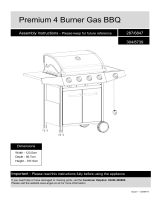
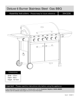
Specifications
Barbecue specifications can be found on the data label
attached to the door panel or the barbecue body.
Gas Cylinder Use & Safety
This is a low pressure barbecue and must only be used
with the hose and regulator supplied. Your barbecue is
designed for use with 9Kg LPG cylinders.
The cylinder should be lled by a reputable gas supplier and
visually inspected and re-qualied at each lling.
Always keep cylinder in an upright position. Always close
the cylinder valve when the barbecue is not in use.
Do not subject the cylinder to excessive heat.
Never Store your Gas Cylinder Indoors.
If you store your barbecue indoors, ALWAYS disconnect the
cylinder rst and store it safely outside. Cylinders must
be stored outdoors in a well ventilated area out of reach of
children, and must not be stored in a building, garage or
any other enclosed area.
Failure to comply with these instructions could result
in a re or explosion which could cause serious
bodily injury, death or property damage.
Accessible parts may be very hot.
Keep young children away.
Any modications of this barbecue may be
dangerous.
Do not move this barbecue during use.
Turn off gas supply at the cylinder after use.
Read instructions before using the barbecue.
Parts sealed by the manufacturer or their agent
must not be manipulated by the user. This barbecue
is only to be used and stored outdoors.
Never operate this barbecue wihout a regulator
Do not test for gas leaks with an open ame
If this information is not followed exactly a re
causing death or serious injury may occur. Do
not store a spare gas cylinder under or near this
barbecue. Never ll the cylinder beyond 85%
full. This barbecue is only to be used and stored
outdoors.
If you smell gas
1. Shut off gas to the barbecue at its source,
if possible.
2. Extinguish any open ame.
3. Open hood.
4. If odour continues immediately call your
gas supplier or re department.
Do not connect your barbecue to a gas cylinder
exceeding this capacity.
Never connect an unregulated gas cylinder to your
barbecue.
Read carefully before assembling and operating
your barbecue.

2
3
Location of your Barbecue
DO NOT use your barbecue in garages, porches, sheds,
breezeways, or other enclosed areas. Your barbecue is to
be used OUTDOORS. The barbecue is not intended to be
installed in or on recreational vehicles and/or boats and
should not be placed under any surface that will burn. Do
not obstruct the ow of combustion and ventilation air
around the barbecue housing.
For your safety:
• Do not store or use petrol or other ammable
liquids in the vicinity of this or any other
appliance.
• Do not store empty or full spare gas cylinders
under or near this or any other appliance.
• Keep the gas hose away from hot surfaces and
protect from dripping grease. Avoid unnecessary
twisting of hose. Visually inspect the hose prior
to each use for cracks, excessive wear or other
damage. Replace the hose if necessary.
• Never test for gas leaks with a lit match or open
ame. Never light barbecue with hood closed or
before checking to ensure the burner tubes are
fully seated over gas valve orices.
• Never lean over cooking surface when lighting.
• Never alter or modify the regulator or gas supply
assembly.
• This barbecue must not be used indoors.
Protect Children
Keep children away from barbecue during use and until
barbecue has cooled after you have nished. Do not allow
children to operate barbecue.
Always ensure that no sporting or physical activities are
carried out in close proximity to the barbecue during use
and while still hot.
Check Barbecue for any Damage
Contact your supplier for assistance regarding replacement
of any damaged or missing parts. Do not operate a
barbecue that appears damaged. Barbecues for use with
gas cylinders are labelled ‘LPG’. Check labelling at the gas
connection on your barbecue.
Ensure the barbecue is set up on a level and stable
surface.
Do not move the barbecue while in use or when hot.
Remove the drip tray before moving.
GENERAL INFORMATION
Nominal Hourly Gas Consumption
Gas Type Number of
BBQ Burners
Injector Size
BBQ Burner
Injector Size
Side Burner
Total Gas
Consumption
MJ/h
Gas
Pressure
kPa
LPG/ULPG
4 0.92mm 0.75mm 58.8 MJ/h 2.75 kPa
MJ/h each 12.6 MJ/h 8.4 MJ/h

4
5
Familiarise yourself with the general information and safety
guidelines located at the front of this manual.
Check:
1. The cylinder is lled. A sloshing sound will be heard when
shaken.
2. The burner controls are in the ‘OFF’ position.
Connecting
1. Ensure cylinder valve is in its full off position.
2. Check for any damage to either the cylinder connection or
the hose. NEVER attempt to use damaged equipment.
3. When connecting the hose to the cylinder tighten the nut
to a positive stop by hand.
4. Open cylinder valve fully. If a leak can be heard at either
end of the hose turn cylinder off and tighten joint. Wait 5
minutes before re-testing and use a soapy water solution
to check the joint. If bubbles appear the connection will
need to be re-tightened.
Refer to P17 for more detailed instructions on connecting
the appliance to the cylinder.
Disconnecting
1. Ensure the burner control is in the ‘OFF’ position.
2. Ensure cylinder valve is in the full off position.
For storage and cylinder exchange, disconnect hose at the
cylinder only, DO NOT disconnect hose from appliance.
Regulator Safety Feature
All QCC regulators (the part that attaches to the gas cylinder
to regulate the ow of gas) have a safety feature included
that restricts gas ow in the event of a gas leak. You can
inadvertently activate this safety feature without having a
gas leak. This typically occurs when you turn on the gas
using the barbecue control knob before you turn on the gas
cylinder valve. If the gas regulator safety feature activates,
the barbecue will operate with reduced output as gas ow is
restricted.
These steps should be taken rst to reset the gas regulator
safety device:
1. Ensure the barbecue hood is open.
2. Turn gas cylinder valve off.
3. Turn off all control knobs.
4. Disconnect the regulator from the gas cylinder.
5. Wait 30 seconds.
6. Reconnect the regulator to the gas cylinder.
7. Leak test the connection using a soapy water solution.
Ensure no bubbles appear before proceeding.
8. Slowly open the gas cylinder valve all the way. Do not put
excessive force on the valve at the full open position, to
avoid damaging the valve.
9. Light barbecue as per the instructions provided.
IMPORTANT: The appliance control knob must be in
the ‘OFF’ position before opening the cylinder valve.
Check performance of burner prior to installing
barbecue plates.
Do not smoke when attempting to ignite barbecue.
Never use volcanic rock, heatbeads or other
material.
Always use protective gloves when handling hot
components.
GENERAL ASSEMBLY
Connecting & Disconnecting to Gas Source
IMPORTANT: Before connecting and disconnecting
barbecue to gas source, make sure burner controls
are in ‘OFF’ position.
CAUTION: When the barbecue is not in use, the gas
must be turned off at the cylinder.
If re–ignition is necessary while the gas barbecue is still
hot, you must wait for a minimum of 5 minutes before
commencing to re–ignite (this allows accumulated gas
fumes to clear).
Note: If for some reason the ignitor fails to
produce a spark at the electrode, barbecue can be
lit by a long barbecue match or using the match
holder supplied. With hood open insert lighted
match into match lighting hole positioned at the
left side of the BBQ body. Push and turn far left
control knob to ‘HIGH’. Burner ignition can be
checked through this hole. Light remaining burners
by cross-lighting.
LIGHTING PROCEDURE
Before lighting your barbecue for the rst time, read the
instructions fully to ensure the barbecue is assembled
correctly and is ready for use.
Remove all point-of-sale material from the barbecue.
Burner Operation & Ignition System Check
1. Open the hood of the barbecue before attempting to
light the burners.
2. Turn all the control knobs clockwise to “OFF” position.
3. With cylinder valve in ‘OFF’ position press the piezo
igniter button (a single click is heard). Check for
sparking to the burners.
4. If spark is not evident at the burner ignition point,
check that the ignition lead is rmly attached to the
control and sparker tip.
5. With sparking established turn the cylinder valve ‘ON’.
6. Push and turn control knob anti-clockwise to ‘HIGH’ and
press the igniter button again.
7. If the burner fails to ignite after several attempts turn
off gas supply at cylinder valve and the control knob off
(clockwise). Wait ve minutes before attempting to
relight with ignition sequence.
8. Following successful ignition, to ignite remaining
burners, turn control knobs to the HIGH position
starting with the burner closest to the ignition burner.
9. Adjust the heat by turning each control knob to the
“HIGH”/”LOW” position.
10. To turn the barbecue ‘OFF’ turn the cylinder valve to
the ‘OFF’ position, then turn the control knobs on the
barbecue clockwise to the ‘OFF’ position.
Side Burner
1. Lift up the cover and ensure it is always open when the
burner is alight.
2. Push and turn the control knob anti-clockwise to HIGH
whilst pressing the piezo ignitor (a single click is
heard). This will light the side burner. Observe if the
burner has lit. If not, repeat this process.
3. If the burner fails to light after several attempts turn
the control knob to OFF and wait a few minutes before
attempting re-ignition.

4
5
OPERATING PROCEDURE
Burn Off Cooking Surfaces
We recommend operating your barbecue on its highest
setting for 15-20 minutes prior to rst use. This aids
removing the oils used during manufacturing. Allow the
cooking surface to cool then we recommend seasoning
it before use. Season your cooking surface by coating
lightly with vegetable oil and bringing slowly up to a high
temperature (do not use olive oil as this burns off at a low
temperature). For best use your cooking surface should
be seasoned two or three times throughout each barbecue
season.
Preheating
It is necessary to preheat the barbecue for at least 5
minutes before cooking certain foods, depending on the
type of food and the cooking temperature. Food that
requires a low cooking temperature, needs only a period of
2-3 minutes preheating.
Cooking Temperatures
‘HIGH’ setting - Use this setting only for fast warm up, for
searing steaks and chops, and for burning food residue
from the grill plates after cooking is over. Rarely, if ever, do
you use the ‘HIGH’ setting for extended cooking.
‘MEDIUM’ setting (mid-way between ‘HIGH’ and ‘LOW’).
Use this setting for most grilling, and for cooking
hamburgers and vegetables.
‘LOW’ setting - Use this setting when cooking very lean cuts
such as sh.
These temperatures vary with outside temperature and the
amount of wind.
When using the temperature gauge in the hood of your
barbecue please note that it measures air temperature. The
air temperature inside your barbecue will never be as hot
as the temperature of the cooking surface.
The hood must be in the open position for lighting.
Do not smoke at any time when attempting to
ignite the barbecue burners.
Do not leave the barbecue unattended when alight.
Problem Possible Reason Solution
Burner will not ignite
Valve on cylinder is closed Open valve on cylinder
Control knob is closed Turn knob to high when lighting
Electronic igniter is faulty Use a long barbecue match
Food is not cooking
or is taking too long
Burner has gone out Check that the gas bottle is not
empty and re-ignite the burner
Cooking surface was not given
enough time to warm up before the
food was applied
Remove the food and give the burner
time to warm the cooking surface
(5-10 minutes)
There is too much food on the
cooking surface
Cook smaller portions
Burner Operation & Ignition System Check
Roasting
For best results when roasting, the outer two burners
should be used on the low to medium setting. Use of the
high setting with the hood down may result in burnt food.
Remove the at hotplate to help with heat circulation.
Preheat the barbecue for a few minutes. Place a roasting
rack or aluminium foil dish onto the ribbed hot plate and
place the meal to be roasted onto the rack or into the dish
and close the hood.
Adjust the control knob to maintain the temperature around
the medium mark (approx. 200o to 230oC).
Approximate Cooking Time
The table below shows approximate cooking times with the
control set to ‘MEDIUM’ temperature.
Barbecue Roasts Minutes
Chicken & Rare Beef (approx.) 45 minutes per Kg
Beef & Medium
Lamb (approx.) 60 minutes per Kg
Pork & Well Done
Beef/Lamb (approx.) 75 minutes per Kg
Refer to Care & Use Guidelines for more information.
The side burner is designed for use with a wok or
cooking pot up to 200mm in diameter.
Use of larger pots may result in discolouration of
the nish.
Important: Never use all burners on high at the
same time when cooking with the hood down.


6
7
ASSEMBLY INSTRUCTIONS
Before assembling the barbecue, read these Instructions carefully.
Assemble the barbecue on a at, clean surface.
The barbecue is heavy.
NOTE: Do not fully tighten all the nuts during the initial stages of assembly.
Caution: Sheet metal can cause injury. Wear gloves when assembling the barbecue.
Tools required: Philips head screwdriver (or cordless drill and bits).
Flat head screwdriver.
Adjustable spanner.
PARTS LIST
A B C D E
F G H I J
K L M N
R
Ø 1/4"-20 x 1/2" ( x 14 ) Ø 1/4"-20 x 1-1/2" ( x 4 ) Ø 1/4"-20 ( x 12 ) Ø 8-32 x 3/8" ( x 2 ) Ø 8-32 x 3/8" ( x 14 )
Ø 7 x 15 ( x 10 ) Ø 11 x 18 ( x 2 ) Hitch Pin Ø 2 ( x 1 ) Clip ( x 1 ) Ø 4 ( x 1 )
Ø 7 ( x 2 )
) 1 x () 1 x ( ) 1 x ( 81 x 11 Ø
Ø 8 x 6 ( x 2 )
P
Battery ( x 1)
HARDWARE PACK
Ref Description Qty Ref Description Qty
AA Top Lid Assembly 1 CI Grease Cup 1
AB Thermometer And Bezel 1 DA Cart Side Panel, Right 1
AC Lid Handle 1 DB Cart Side Panel, Left 1
AD Lid Bumpers - Front 2 DC Bottom Shelf 1
AE Lid Bumpers - Back 2 DD Front Panel 1
BA Burner Box Assembly 1 DE End Caps 2
BB Burners 4 DF Wheel 2
BC Flame Tamers 2 DG Wheel Cap 2
BD Cooking Grill 1 DH Wheel Axle 1
BE Cooking Plate 2 DI Upper Back Brace 1
BF Warming Rack 1 EA Side Shelf Table - Right 1
CA Control Panel 1 EB Side Shelf Fascia - Right 1
CB Manifold Assembly 1 EC Side Shelf Handle & Hooks - Right 1
CC Regulator & Hose Assembly 1 ED Side Shelf Table - Left 1
CD Bezel, Control Knob 4 EE Side Burner Support Frame 1
CE Control Knob 4 EF Side Burner Insert Tray 1
CF Piezo Ignition Assembly 4 EG Side Shelf Fascia - Left 1
CG Piezo Ignition Button 1 EH Side Burner Grid 1
CH Grease Cup Hook 1 EI Side Burner 1

8
9
C
x4
B
x4
B
DB
DC
DA
DB
DC
DA
DD
E
x6
ASSEMBLY INSTRUCTIONS
Step 1
Assemble the left and right side cart panels
(DA & DB) to the bottom shelf (DC) as
shown.
Note: The left cart panel has large holes on
the end of the legs for assembling the wheel
axle (DH).
Step 2
Assemble the front panel (DD) to the left
and right cart side panels as shown.

8
9
DI
DB
DA DC
DH
DF
DG
DF
DG
E
x4
K
x1c
H
x1b
G
x2a
DE
DE
a
a
c
b
ASSEMBLY INSTRUCTIONS
Step 3
Assemble the upper back brace (DI) to the
left and right cart side panels as shown.
Step 4
A. Place wheel (DF) and wheel spacer (G)
onto wheel axle (DH). The ‘cone’ side of
the wheel should be against cart side
panel.
B. Insert wheel axle assembly (DH) through
wheel axle hole in the front and rear of
the left cart side panel (DB) as shown.
C. To complete wheel assembly, position the
wheel washer (K), wheel (DF), wheel
spacer (G) and hitch pin (H) onto wheel
axle (DH) as shown.
D. Insert end caps (DE) into cart right side
panel (DA).

10
11
AB
+
CC
C
EA
EB
BA
ED
EG
Back View
A
x4
ASSEMBLY INSTRUCTIONS
Step 5
Note: Two people are required for this step.
Ensure the regulator hose is hanging outside
of cart.
Position the lid and burner box assembly
(A & B) onto the cart assembly (C) and
assemble.
Step 6
Right Side Shelf Assembly
Insert the right side shelf assembly (EA & EB)
into the support brackets located on the right
side of the burner box assembly (BA).
Left Side Shelf Assembly
Insert the left side shelf assembly (ED & EG)
into the support brackets located on the left
side of the burner box assembly (BA).


12
13
J
x1
I
x1
EIEI
ASSEMBLY INSTRUCTIONS
Step 11
Assemble the side burner by positioning the
burner (EI) through the opening in the side
burner support frame (EE).
Step 12
Ensure the burner (EI) engages the side
burner valve.
Fix side burner to burner support using wing
nut provided. Attach side burner electrode to
igniter.


16
17
ASSEMBLY INSTRUCTIONS
Step 18
Hang the grease cup hook (CH) from the
bottom of the burner box (BA) and place
grease cup (CI) into position.
Failure to assemble grease cup will
cause hot grease to drip from the
bottom of the BBQ burner box, with
the risk of re, property damage, or
personal injury.
Step 19
Position the 9kg LPG cylinder onto the
bottom shelf (DC). Follow instructions
overleaf for leak testing.
Step 17
To assemble the warming rack (BF), insert
the stationary wire into the holes on the sides
of the lid. Insert warming rack pivot legs into
the holes on the inside of the burner box
assembly, as shown.
Insert AA sized battery (P) into ignition
module.
CH
CI
1
2
CH
CI
BF
Stationary
Wire
Pivot
Legs

16
17
ASSEMBLY INSTRUCTIONS
Step 20
Attach the regulator to your gas cylinder.
Step 21
Turn on the gas cylinder ensuring that all of the
controls on the BBQ are turned OFF at this point.
DO NOT ATTEMPT TO LIGHT THE BBQ!!.
Step 22
Use a solution of soapy water (dishwashing liquid
and water is fine). Brush it on or use a spray
bottle as shown in the drawing. Ensure the
connections have a good coating.
Step 23a
If the connection is leaking, bubbles will start to
grow in the soapy solution. If this happens shut
off the gas supply at the cylinder.
Step 23b
Tighten the connections using a crescent then
repeat steps 21-22.
Step 23c
The connection is gas tight when no bubbles
grow around the gas connection.

18
19
CARE & MAINTENANCE
Care & Maintenance
As with all appliances, proper care and maintenance will
keep them in top operating condition and prolong their life.
Your new gas barbecue is no exception. By following these
cleaning procedures on a timely basis, your barbecue will
be kept clean and working properly with minimum effort.
Beware of spiders and wasps. Burner tube should
be inspected and cleaned periodically.
Spiders and small insects occasionally spin webs or make
nests in the burner tubes during warehousing and transit.
These webs can lead to a gas ow obstruction which could
result in a re in and around the burner tubes.
This type of re is known as ‘FLASH-BACK’ and can cause
serious damage to your barbecue and create an unsafe
operating condition for the user. Although an obstructed
burner tube is not the only cause of ‘FLASH-BACK’ it is the
most common cause and frequent inspection and cleaning
of the burner tubes is necessary.
Flash-Back
If re occurs in and around the burner, immediately turn off
gas at its source and turn the burner control to ‘OFF’, wait
until the barbecue has cooled, then clean the burner tubes
and burner ports.
Cleaning the Grill Plates
After cooking, turn burner control to ‘OFF’ and let barbecue
cool before attempting to clean the grill plates. Before rst
use and periodically, it is suggested that you wash the grill
plates in a mild soap and warm water solution. You can use
a wash cloth to clean your barbecue plates.
Care of Cooking Surface
Use and care of the cooking surface is important.
Do not overheat the cooking surface with the hood down or
no food on the cooking surface.
Cleaning the Drip Tray
To avoid fat or grease dripping from the barbecue remove
and empty the drip tray after each use. A small amount of
water can be placed in the drip tray before use to help with
fat removal. Wait until the drip tray is cool to touch before
disposing of contents.
The drip tray should be washed periodically in a mild
detergent and warm water solution.
To avoid any are-ups, it is recommended that
the drip tray be checked and emptied regularly.
Contents of the drip tray may be very hot during
cooking. If emptied during extended cooking
extreme caution should be taken and direct contact
by hand should be avoided at all times. Allow to cool
completely before disposing of the contents.
Refer to Care & Use Guidelines for more information.

18
19
DIAGRAMMATIC REPRESENTATIONS OF OUTDOOR AREAS
The following figures are diagrammatic representations of outdoor areas. Rectangular areas have been used in these figures –
the same principles apply to any other shaped area.
SAFE APPLIANCE LOCATIONS
This appliance shall only be used in an above ground open-air situation with natural ventilation, without stagnant areas,
where gas leakage and products of combustion are rapidly dispersed by wind and natural convection.
Any enclosure in which the appliance is used shall comply with the following:
An enclosure with walls on all sides, but at least one permanent opening at ground level and no overhead
cover (see Example 1).
Within a partial enclosure that includes an overhead cover and no more than two walls (see Example 2 & 3).
Within a partial enclosure that includes an overhead cover and more than two walls, the following
will apply:
at least 25% of the total wall area is completely open, and
at least 30% of the remaining wall area is open and unrestricted (see Example 4 & 5).
In the case of balconies, at least 20% of the total wall area shall be and remain open and unrestricted.
Gasmate® is a registered trademark of: Sitro Group Australia Pty Ltd www.gasmate.com.au
Aber, Hamilton, N.Z. www.gasmate.co.nz
Gasmate®is a registered trademark of: Sitro Group Australia Pty Ltd www.sitro.com.au
Aber, Hamilton, N.Z. www.gasmate.co.nz
SAFE APPLIANCE LOCATIONS
This appliance shall only be used in an above ground open-air situation with natural ventilation, without
stagnant areas, where gas leakage and products of combustion are rapidly dispersed by wind and natural
convection.
Any enclosure in which the appliance is used shall comply with one of the following:
An enclosure with walls on all sides, but at least one permanent opening at ground level and
no overhead cover (see Example 1).
Within a partial enclosure that includes an overhead cover and no more than two
walls (see Example 2 & 3).
Within a partial enclosure that includes an overhead cover and more than two walls,
the following will apply:
at least 25% of the total wall area is completely open, and
at least 30% of the remaining wall area is open and unrestricted (see Example 4 & 5).
In the case of balconies, at least 20% of the total wall area shall be and remain open and unrestricted.
The following figures are diagrammatic representations of outdoor areas. Rectangular areas have been used in these
figures - the same principles apply to any other shaped area.

/