Page is loading ...

Model U421
OWNER'S MANUAL
Manual No. 513595 Mar., 2003 Rev. 1


Need Parts or Service?
We stock the parts you need.
Our Technicians are factory
trained and are certified in the
Stoelting Technicare program.
Model No.: _______________________
Serial No.: _______________________
Purchase Date: ____________________
Start-Up Date:____________________
CALL
Distributor: _________________________
Phone No.: _________________________
(fill in or affix label)


STOELTING, LLC Tele: 920-894-2293
502 Hwy 67
Kiel, WI 53042-1600 Fax: 920-894-7029
STOELTING® OWNER'S MANUAL
FOR
MODEL U421
CAB MODEL SOFT-SERVE PRESSURIZED FREEZER
This manual provides basic information about the freezer. Instructions and suggestions are given
covering its basic operation and care.
The illustrations and specifications are not binding in detail. We reserve the right to make changes
at any time without notice, to the freezer and its components, without incurring any obligation to
modify or provide new parts for freezers built prior to date of change.
DO NOT ATTEMPT to operate the freezer until instructions and safety precautions in this manual
are read completely and are thoroughly understood. If problems develop or questions arise in
connection with installation, operation or servicing of the freezer, contact the company at the
location listed below.


TABLE OF CONTENTS
Section 1 .............................................................................................................. 1
1.1 Description.............................................................................................. 1
1.2 Specifications.......................................................................................... 1
Section 2 .............................................................................................................. 3
2.1 Safety Precautions .................................................................................. 3
2.2 Shipment & Transit .................................................................................. 4
2.3 Freezer Installation................................................................................... 4
2.4 Installing Permanent Wiring...................................................................... 4
2.5 Mix Pump ................................................................................................ 5
Section 3 .............................................................................................................. 9
3.1 Safety Precautions .................................................................................. 9
3.2 Operating Controls and Indicators ............................................................ 9
3.3 Sanitizing ................................................................................................ 10
3.4 Initial Freeze Down and Operation ........................................................... 11
3.5 Mix Information ........................................................................................ 12
3.6 Operation of Mix Pump ............................................................................ 12
3.7 Removing Mix from the Freezer ............................................................... 13
3.8 Cleaning the Freezer ............................................................................... 13
3.9 Disassembly of Freezer Parts.................................................................. 13
3.10 Routine Cleaning ..................................................................................... 14
3.11 Mix Pump Cleaning ................................................................................. 15
3.12 Sanitize Freezer Parts ............................................................................. 15
3.13 Assembly of Freezer................................................................................ 15
Section 4 .............................................................................................................. 19
4.1 Freezer Adjustment ................................................................................. 19
4.2 Product Temperature Adjustment ............................................................. 19
4.3 Overrun Adjustment ................................................................................. 19
4.4 Mix Pump Hose Reposition ..................................................................... 20
4.5 Mix Pump Hose Replacement.................................................................. 20
4.6 Cab Temp. Adjustment............................................................................. 20
4.7 Drive Belt Tension Adjustment.................................................................. 20
4.8 Condenser Cleaning (Air Cooled Freezers) ............................................. 21
4.9 Preventative Maintenance........................................................................ 21
4.10 Extended Storage ................................................................................... 21
4.11 Troubleshooting ....................................................................................... 22
Section 5 .............................................................................................................. 27
5.1 How to Order Replacement Parts ............................................................ 27
5.2 Parts Lists and Reference Drawings........................................................ 27

ILLUSTRATIONS
Figure 1 Model U421 Freezer ..............................................................1
Figure 2a Air-Cooled Specifications ......................................................2
Figure 2b Water-Cooled Specifications .................................................2
Figure 3 Decal Locations.....................................................................3
Figure 4 Water/Electrical Connections .................................................4
Figure 5 Auger Rotation.......................................................................5
Figure 6 Mix Hose Installation...............................................................5
Figure 7 Mix Pump...............................................................................6
Figure 8 4 Way Tee .............................................................................7
Figure 9 Mix Inlet Tube & Probe Assy. Clip...........................................7
Figure 10 Hose Holder...........................................................................7
Figure 11 Operating Controls.................................................................9
Figure 12 Air Bleed Valves ....................................................................10
Figure 13 Draining Sanitizer ..................................................................11
Figure 14 Mix Container.........................................................................11
Figure 15 Mix Pumps.............................................................................12
Figure 16 Auger Flight Wear & Front Auger Support Bushing Wear .......13
Figure 17 Front Door Disassembly ........................................................14
Figure 18 Auger Flight Removal.............................................................14
Figure 19 Rear Seal Removal ................................................................14
Figure 20 Cleaning Feed Tube ..............................................................16
Figure 21 Cleaning Air Tube ..................................................................17
Figure 22 Removable Parts ...................................................................17
Figure 23 Rear Seal Lubrication ............................................................17
Figure 24 Spring Installation...................................................................18
Figure 25 Front Door Assembly .............................................................18
Figure 26 Potentiometer ........................................................................19
Figure 27 Overrun Adjustment................................................................19
Figure 28 Temperature Control Cab ......................................................20
Figure 29 Belt Adjustment......................................................................21

1
SECTION 1
INTRODUCTION
1.1 DESCRIPTION
The Stoelting U421 floor model freezer is pressure fed.
The freezer is equipped with fully automatic controls to
provide a uniform product. The freezer is designed to
operate with almost any type of commercial soft-serve
or non-dairy mixes available, including ice milk, ice cream,
yogurt, and frozen dietary desserts.
This manual is designed to assist qualified personnel and
operators in the installation, operation and maintenance
of the Stoelting Model U421 pressure freezer.
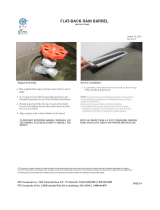
Figure 1. Model U421 Freezer
1.2 SPECIFICATIONS
124ULEDOM
SNOISNEMID
)mc761("4/3-56:thgieH)mc101("4/3-93:htpeD)mc86("4/3-62:htdiW
THGIEW
)gk244(etarC/w.sbl579)gk5,914(.sbl529
LACIRTCELE
srotomevird.P.H2owT,hP3rohP1,tlov032/802
srosserpmoCHUTB06811owTdna
GNILOOC
pot)mc52("01dnaecnaraelcdnuoralla)mc6,7("3s'qer.deloocriaroretaW
.sgnittifniarddnaretawTPN)mc3,1("2/1s
'qerdeloocretaW.ecnaraelc

2
Figure 2a. Air-Cooled Specification
Figure 2b. Water Cooled Specification

3
SECTION 2
INSTALLATION INSTRUCTIONS
2.1 SAFETY PRECAUTIONS
Do not attempt to operate the freezer until the safety
precautions and operating instructions in this manual are
read completely and are thoroughly understood.
Take notice of all warning labels on the freezer. The labels
have been put there to help maintain a safe working
environment. The labels have been designed to withstand
washing and cleaning. All labels must remain legible for
the life of the freezer. Labels should be checked periodi-
cally to be sure they can be recognized as warning labels.
1 324722 Decal Mix Low
2 324798 Decal Clean-Off-Serve Switch
3 324141 Decal Caution - Rotating Blades
4 723526 Tag Read Manual & All Decals
6 324393 Decal Stoelting Swirl Logo
7 324800 Decal Cab ON/OFF
8 324799 Pump On/Off
9 324208 Decal Refrig. Leak Check
11 324103 Decal Caution - Rotating Shaft
12 324686 Decal Danger Automatic Start
13 324107 Decal Caution Moving Parts
14 324125 Decal Elect.Shock Hazard
15 324151 Decal Field Connections
16 324198 Decal Attention Installer
17 130000 Bag, Envelope Front Loading
18 324584 Decal Adequate Ventilation
19 324158 Decal Copper Conductors Only
20 324106 Decal Caution Wiring Mat'l
22 324566 Decal Wired According To
23 324015 Decal 2 x 1-1/4 Blk on White
24 723552 Tag, Caution - Supply Voltage
26 324803 Decal GM Header (Stoelting Logo)
26 324804 Decal GM Header (Stoelting Swirl)
26 324805 Decal DQ Header (DQ Logo)
27 324346 Decal Caution Hazard.Moving
28 324797 Decal Standby/Serve
29 324242 Decal Temperature Control
30 324200 Decal Manual Reset
32 324014 Decal Arrow
33 324496 Decal Freezing
Water Cooled Only
A 324065 Decal Water Inlet
B 723525 Tag Winterizing Disconnect Line
C 723517 Tag, W/C Tower Instructions
D 324107 Decal Caution Moving Parts
Air Cooled Only
E 324346 Decal Hazardous Moving Parts
F 324107 Decal Caution Moving Parts
Figure 3. Decal Locations
If danger, warning or caution labels are needed, indicate
the part number, type of label, location of label, and
quantity required along with your address and mail to:
STOELTING, LLC
ATTENTION: Customer Service
502 Hwy. 67
Kiel, Wisconsin 53042

4
2.2 SHIPMENT AND TRANSIT
The freezer has been assembled, operated, and in-
spected at the factory. Upon arrival at the final destina-
tion, the freezer must be checked for any damage which
may have occurred during final transit.
With the method of packaging used, the equipment should
arrive in excellent condition. THE CARRIER IS RESPON-
SIBLE FOR ALL DAMAGE IN TRANSIT, WHETHER VIS-
IBLE OR CONCEALED. Do not pay the freight bill until
the freezer has been checked for damage. Have the car-
rier note any visible damage on the freight bill. If concealed
damage and/or shortage is found later advise the carrier
within ten days and request inspection. The customer
must place claim for damage and/or shortages in ship-
ment with the carrier. Stoelting, LLC. cannot make
any claims against the carrier.
2.3 FREEZER INSTALLATION
WARNING
Installation must be performed by a qualified electri-
cian/refrigeration specialist. Incorrect installation may
cause personal injury, severe damage to the machine
and will void factory warranties.
WARNING
Lifting hazard
Do not attempt to lift freezer manually. Use proper lift-
ing equipment such as a forklift, lift table, or pallet
jack, with lifting device positioned beneath the freezer’s
base. Ensure that personnel remain clear of suspended
load. Failure to do so may result in personal injury
and/or damage to the freezer that will void any factory
warranties.
Installation of the freezer involves moving the freezer close
to its permanent location, removing all crating, setting in
place, assembling parts, and cleaning.
A. Uncrate the freezer.
B. Install the four casters. Turn the threaded end into
the freezer until zero threads are showing. To level,
turn out casters no more than 1/4" maximum, then
tighten all jam nuts.
C. The freezer must be placed in a solid level position.
NOTE
Accurate leveling is necessary for correct drainage of
freezer barrel and to insure correct overrun.
Figure 4. Water/Electrical Connections
D. The freezer must have a minimum of 3" (7,5cm)
-6" (15cm) high ambient conditions- of space on all
sides and 10" (25cm) at the top for proper circula-
tion.
CAUTION
Risk of product damage
Air cooled condenser requires proper ventilation. Fail-
ure to provide adequate ventilation will void factory
warranties.
E. Water-cooled freezers need an adequate water
supply. Install 1/2" (12,7mm) pipe or 1/2" (12,7mm)
inside diameter copper water line to the freezer.
Connect water outlet to a drain using a 1/2"
(12,7mm) inside diameter line. Automatic washer
hoses work well for final connections. All water
connections must comply with local codes. Fig. 4.
CAUTION
Flush all water lines before installation. In stores with
sediment in water, add suitable filter or strainer to water
inlet.
F. Place the CLEAN-OFF-SERVE switches in the OFF
position before continuing. Figure 11.
2.4 INSTALLING PERMANENT WIRING
Permanent wiring is required by local codes, the following
procedure must be performed:
WARNING
Hazardous voltage
High voltage will shock, burn or cause death. Turn off
and lock out main power disconnect before installing
wiring. Do not operate machine with cabinet panels
removed.

5
2.5 MIX PUMP
A. Mix Pump Hose Installation
Follow the steps below to install the mix pump hose.
1. Turn pump on.
2. Feed one end of mix pump hose into the entering or
pick-up hose side (left) of black cover.
3. Gently push the hose into the black cover until it
begins to feed.
4. Allow the hose to feed itself thru the pump until 6"
(15cm) remains on the entering side.
Figure 6. Mix Hose Installation
A. Refer to the nameplate at the rear of the freezer for
specific electrical requirements. Make sure the
power source in the building matches the freezer
nameplate requirements. Bring the wires into the
junction boxes through the access holes in the
bottom rear of the freezer. Figure 4.
NOTICE
Three phase freezers in areas of unbalanced
electrical loads require special attention when
connecting input electrical power. The unbal-
anced leg of power (called wild or high) must be
connected to L2 in the junction box.
NOTICE
Verify actual voltage. Machine is equipped with
a transformer to supply a control circuit. You
will need to check voltage on terminal C1 and
C2 on EACH control board. (Located behind
decorative header panel on front of machine.)
Transformers are located behind electrical panel
enclosing control boards. Access these by re-
moving top panel of machine. Actual transformer
voltage should read 20-28 V.A.C.
B. Remove the lower back panel and the two junc-
tion box covers located at the bottom of the
freezer.
C. lnstall permanent wiring according to local
code.
D. Check the auger shaft rotation by placing the
MAIN DRIVE switch in the CLEAN position.
Auger shaft rotation is clockwise as viewed through the
clear plastic front door. If the rotation is not clockwise,
turn main electrical power OFF. Then reverse L1 and L3
electrical power lines to the junction box (three phase
only). Re-check auger shaft rotation. Figure 5.
Figure 5. Auger Rotation
6" (15cm)

6
B. Connect 1/2 inch (12,7mm) I.D. plastic food grade
tubing to check valve and then to the mix con-
tainer. Observe check valve flow arrow. Secure
with hose clamps. Then place assembly thru hole
in cover and install retainer clip. Figure 9.
C. Connect 1/2 inch (12,7mm) I.D. plastic food grade
tubing between the large port of air/mix tee and
refrigerated mix transfer line. Secure with large
hose clamp or equivalent. Figure 9.
CAUTION
Air/Mix tee must remain below the black cover/
clamp. If the tee is above the pump mix will
drain to the air compressor resulting in pump
damage.
D. Connect mix low cords. Figure 9.
STAINLESS 4-WAY TEE1177816 / 376017
Figure 7. Mix Pump
5.Turn pump off.
6.Connect mix pump hose to pickup hose
adapter using small hose clamp.
CAUTION
DO NOT TWIST MIX PUMP HOSE.
7.Turn pump off.
8.Allow remaining 6" (15cm) of tubing to feed hru
pump until hose adapter prevents further feeding.
9.Turn pump off.
10.Connect free end of mix pump hose to "4
way Tee"

7
Figure 8. 4 Way Tee
Figure 9. Mix Inlet Tube & Probe Assy. Clip
Low Mix Cord
Cover
Retainer
Clip
Mix
Container
ÌÌ
ÌÌ
Ì
ÉÉ
ÉÉ
É
ÇÇ
ÇÇ
Ç
Hose Holder
ÈÈ
ÈÈ
È
Figure 10. Hose Holder
Refrigerated
Mix Transfer
Line
ÅÅ
ÅÅ
Å
Large Port
Air/Mix Tee
4 Way Tee
ÆÆ
ÆÆ
Æ
ÅÅ
ÅÅ
Å

8

9
SECTION 3
INITIAL SET-UP AND OPERATION
3.1 SAFETY PRECAUTIONS
SAFE OPERATION IS NO ACCIDENT; observe these
rules:
A. Know the freezer. Read and understand the operat-
ing instructions.
B. Notice all warning labels on the freezer.
C. Wear proper clothing. Avoid loose fitting garments,
and remove watches, rings or jewelry which could
cause a serious accident.
D. Maintain a clean work area. Avoid accidents by
cleaning the area and keeping it clean.
E. Stay alert at all times. Know which switch, push
button or control you are about to use and what
effect it is going to have.
F. Disconnect electrical power for maintenance.
Never attempt to repair or perform maintenance on
the freezer until the main electrical power has been
disconnected.
G. Do not operate under unsafe operating condi-
tions. Never operate this freezer if unusual or exces-
sive noise or vibration occurs.
Figure 11. Operating Controls
3.2 OPERATING CONTROLS AND INDICATORS
Before operating the freezer, it is required that the opera-
tor know the function of each operating control. Refer to
Fig.11 for the location of the operating controls on the
freezer.
WARNING
Hazardous voltage
The CLEAN-OFF-ON switch must be placed in the
OFF position when disassembling for cleaning or
servicing. The freezer must be disconnected from
electrical supply before removing any access panel.
Failure to disconnect power before servicing could
result in death or serious injury.
A. Spigot Switch
When the spigot handle is opened the SPIGOT
switch will start the auger drive and refrigeration
systems. When the spigot handle is closed, the drive
motor and compressor will remain on until the product
in the barrel reaches the proper temperature.
B. Clean-Off-Serve Switch
The CLEAN-OFF-SERVE switch is a three position
toggle switch used to control the operation of the
refrigeration system and auger. When the switch is
placed in the CLEAN position, the refrigeration sys-
tem will beoff and auger will rotate for cleaning.

10
When the switch is placed in the OFF position, the
refrigeration system and auger will not operate.
When the switch is placed in the SERVE position,
the refrigeration system and auger will operate auto-
matically. The switch should be placed in the SERVE
position for normal operation.
C. Cabinet-Off-On Switch
The CABINET-OFF-ON switch is a two position
toggle switch. When the switch is placed in the OFF
position, the lower cabinet refrigeration system will
not run. When the switch is placed in the ON
position, the lower cabinet refrigeration system will
run until the preset temperature is reached; then
cycle ON and OFF to maintain that temperature.
D. Cab Indicator Light
A flashing light indicates the cab OFF-ON switch is
in the OFF position, no refrigeration. Place the OFF-
ON switch in the ON position for cab refrigeration.
E. Pump Switch
The pump motor switch is a two position toggle
switch. When the switch is placed in the OFF
position, the pump will not run. When the switch is
placed in the ON position, the pump will run until the
preset pressure is reached, then cycle ON and OFF
as product is drawn to maintain that pressure.
F. Standby/Serve Switch
The standby/serve switch is a two position toggle
switch. When the switch is placed in the standby
position the freezer will cycle to maintain a tempera-
ture below 41°F (-15°C). When the switch is in the
Serve position the freezer will cycle to maintain a
servable product.
G. Freezing Switch
The freezing switch is a two position toggle
switch. When the switch is placed in the MAXIMUM
position the freezer will be forced to run 30 seconds
after the temperature control is satisfied.
H. High Head Pressure Cut Out
If the head pressure exceeds 445 psig (28 bar) air
cooled andwater cooled, the high head pressure
cutout will trip. The reset button can be accessed
from the side of thefreezer.
I. Low Mix Light
The low mix light will illuminate when the liquid level
in the mix container drops below two gallons.
J. Front Door Safety Switch
The front door safety switch prevents the auger from
turning when the front door is removed. The switch
is open when the door is removed and closed when
the door is properly installed.
3.3 SANITIZING
Sanitizing must be done after the freezer is clean and just
before the freezer is filled with mix. Sanitizing the night
before is not effective. However, you should always clean
the freezer and parts after using it.
WARNING
The United States Department of Agriculture and
the Food and Drug Administration require that
all cleaning and sanitizing solutions used with
food processing equipment be certified for this
use.
When sanitizing the freezer, refer to local sanitary regula-
tions for applicable codes and recommended sanitizing
products and procedures. The frequency of sanitizing must
comply with local health regulations. Mix sanitizer ac-
cording to manufacturer’s instructions to provide a 100
parts per million strength solution. Mix sanitizer in quan-
tities of no less than 2 gallons (7.5 liters) of 120°F (49°C)
water. Allow sanitizer to contact the surfaces to be sani-
tized for 5 minutes. Any sanitizer must be used only in
accordance with the manufacturer’s instructions.
In general, sanitizing may be conducted as follows:
A. Clean and lubricate parts.
B. Prepare 3 gallons (11 liters) of sanitizing solution
following manufacturer's instructions, and pour
into storage container.
C. Place the mix pump switch in the ON position and
open air bleed valve on the front door by pushing
valve in and holding. Figure 12.
D. Let sanitizing solution fill the freezer barrel to air bleed
valve, then close the valve by pulling out to lock in
place.
Figure 12. Air Bleed Valves
Air Bleed Valves
CAUTION
Avoid prolonged contact of sanitizer with freezer
parts. Prolonged contact of sanitizer with freezer
may cause corrosion of stainless steel parts.

11
Figure 13. Draining Sanitizer
E. Place the CLEAN-OFF-SERVE switch in the CLEAN
position.
F. Check for leaks when the freezer barrel is first
pressurized with sanitizing solution.
1. Check for leaks at the plastic front door, the
0-rings may not be sealed.
2. Check the drain tray located at the right or left
side of the freezer for leaks.
3. Check inside cab unit for leaks at hose connec-
tions and manifolds.
G. Using a sanitized soft bristle brush or equivalent,
dipped in sanitizing solution, clean mix container.
H. After five minutes, open spigot to expel sanitizing
solution. Drain all solution from freezer. Figure 13.
I. Close the spigot and place the mix pump switch and
the CLEAN-OFF-SERVE switch in the OFF position.
The freezer is now sanitized and ready for adding mix.
3.4 INITIAL FREEZE DOWN AND OPERATION
This section covers the recommended operating proce-
dures to be followed for the safe operation of the freezer.
A. Sanitize just prior to use according to instructions.
B. Prepare the desired amount of mix and then fill stor-
age container with approximately 3 gallons (11
liters) or more of mix. Place a container(s) of mix in
the cooler. If drawing from a storage container, place
the draw tube through the cover to the bottom of the
container. If drawing from a bag in a box, remove the
cap, push out all of the air, and insert the adaptor.
C. Place the mix pump switch, located on the front of
the freezer, in the ON position. Immediately open
the spigot and let approximately 8 ounces (236 mil-
liliters) of liquid mix with sanitizing solution drain out
of the spigot.
D. Close the spigot and open the air bleed valve on the
front door by pushing the valve in and holding. Allow
the barrel to fill until the mix level is 1/2 inch (12,7
mm) below air bleed valve, then release valve and
pull closed to lock in place.
E. Start the compressor and drive by placing the
CLEAN-OFF-SERVE switch in the SERVE position.
F. The product will be ready to serve after approximately
20 minutes.
Figure 14. Mix Containers
Mix Low
Sensor

12
G. The refrigeration is automatically actuated when the
spigot is opened. For normal dispensing, open the
spigot no more then 90°. (This is when the handle
knob is pointed directly away from the front door.)
This position provides excellent control over the prod-
uct and aids in making desired shaped portions.
Close spigot completely after dispensing.
It is possible to overdraw if rate of draw is exceeded for
extended periods. If the freezer is overdrawn, the result
will be a soft product and air pops. To draw a quart prop-
erly, it is necessary to use a little more than one minute.
During normal operation it is not necessary to be overly
concerned about capacity. But, if there is an order for six
products at one time, each using 9 ounces (266 milli-
liters) of product, it should be considered as 54 ounces
(1,60 liters) of product. Approximately two minutes must
be allowed for this drawing. After a while most operators
will sense, or feel, when the freezer is beginning to fall
behind, and will slow up on the rate of draw so as not to
exceed capacity.
3.5 MIX INFORMATION
Mix can vary considerably from one manufacturer to
another. Differences in the amount of butter-fat content and
quantity and quality of other ingredients have a direct
bearing on the finished frozen product. A change in freezer
performance that cannot be explained by a technical
problem may be related to the mix.
Proper product serving temperature varies from one
manufacturer's mix to another. Mixes should provide a
satisfactory product in the 17° to 20°F (-8,3° to -6,6°C)
range.
When checking the temperature, stir the thermometer in
the frozen product to read the true temperature.
Mix does not improve with age. Old mix, or mix that has
been stored at too high a temperature, can result in a
finished product that is less than satisfactory from the
appearance and taste standpoint. To retard bacteria growth
in dairy based mixes, the best storage temperature range
is between 36° to 40°F (2,2° to 4,4°C).
3.6 OPERATION OF MIX PUMP
The PUMP switch is located on the front of the freezer.
When the pump switch is placed in the ON position, the
mix pump motor will be actuated to pump mix into the
freezer cylinder. When the set pressure is reached, the
mix pump will shut off automatically. When the switch is
placed in the OFF position, the mix pump will be inopera-
tive.
NOTE
The mix pump motor is equipped with an internal
overload that will "kick-out" when the motor is over-
loaded. Consult the trouble shooting section for
corrective information. The internal overload will
automatically reset after cooling. If the condition con-
tinues, contact a qualified service person.
The pump hose must be repositioned every 1 - 2 weeks or
60 hours of operation. Failure to comply will result in
reduced mix pump liquid capacity, dispense stoppage,
popping, and possible mix pump hose leakage.
Find a system that works for you. Operating until hose
breaks shortens pump life, causes downtime and in-
creased cleaning costs.
A. Mix Operation: The peristaltic mix pump contains
one continuous mix pump hose. When looking at the
face of the peristaltic mix pump, the left side of the
hose is the suction or pickup. The right side of the
hose is the discharge. Mix is drawn up the suction
side of the hose and transferred thru the discharge
side to the freezer. Figure 15.
B. Air Operation: The air compressor operates concur-
rently with the peristaltic mix pump. Air enters thru a
check valve on the piston downstroke. The air is
discharged thru a second check valve, on the piston
upstroke. The air and mix join at the tee and then
travel to the freezer.
Figure 15. Mix Pumps
ÉÉ
ÉÉ
É
Pressure
Switch
Manifold
Mix
Discharge
4 Way Tee
ÆÆ
ÆÆ
Æ
ÊÊ
ÊÊ
Ê
Mix
Intake
ÆÆ
ÆÆ
Æ
ÆÆ
ÆÆ
Æ
Hose Holder
/