
H.C. Duke & Son, LLC P/N 184981 November 2013 Printed in U.S.A.
High Capacity
Twin Twist
Soft Serve Freezer
Model 959R
184981 - 11/13
OPERATOR’S MANUAL
with Illustrated Parts List


iii
184981
Operator’s Manual
for the
Soft Serve Twist Freezer
Model 959R
All contents © Copyright 2014 H.C. Duke & Son, LLC 2116 Eighth Avenue, East Moline, Illinois 61244

iv
DUKE Model 959R Soft Serve Freezer
184981
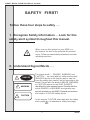
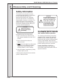
SAFETY FIRST!
Follow these four steps to safety ....
WARNING
DANGER
DANGER
When you see this symbol on your 959R or in
this manual, be alert to the potential for personal
injury. Follow recommended precautions and safe
operating practices.
The signal words — DANGER, WARNING and
CAUTION — are used with the safety alert symbol.
(DANGER decals on the freezer may or may not
have the safety alert symbol, but the message is the
same.) Decals with the words DANGER, WARNING,
or CAUTION appear on the 959R. DANGER
identies the most serious hazard. Decals with the
words DANGER or WARNING are typically near
specic hazards on the 959R. General precautions
are listed on CAUTION safety decals.
In this manual, CAUTION messages with the safety
alert symbol call attention to safety messages.
CAUTION
1. Recognize Safety Information ....Look for this
safety alert symbol throughout this manual.
2. Understand Signal Words ....

v
DUKE Model 959R Soft Serve Freezer
184981
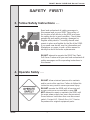
SAFETY FIRST!
3. Follow Safety Instructions ....
4. Operate Safely ....
Read and understand all safety messages in
this manual and on your 959R. Take notice of
the location of all decals on the 959R and keep
the safety decals in good condition. Check them
periodically and replace missing, damaged, or
illegible safety decals. The safety decals must
remain in place and legible for the life of the 959R.
If you need new decals, use the information and
illustrations on pages iv and v of this manual to
identify the decal and order replacements.
DO NOT attempt to operate the 959R Twin Twist
Soft Serve Freezer until you read and understand all
safety messages and the operating instructions in
this manual.
DO NOT allow untrained personnel to maintain
and/or service this machine. Failure to follow this
instruction may result in severe personal injury.
DO NOT operate the 959R until all service and
access covers are secured with screws. DO
NOT attempt to repair or maintain the 959R until
the main power supply has been disconnected.
Some freezers have more than one disconnect
switch. Contact H.C. Duke & Son, LLC Service
Department for original equipment parts.
Safety
First!

vi
DUKE Model 959R Soft Serve Freezer
184981
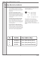
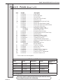
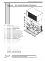
1 HC165025-01 Decal—Beater Warning Twist (1)
2 HC165025-02 Decal—Beater Warning Black (1)
3 HC165126 Decal—Panel Removal Warning (3)
Do not attempt to operate the freezer
until all safety precautions and operating
instructions in this manual are read and
understood.
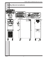
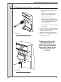
Take notice of all warning, caution,
instruction and information decals (or la-
bels) on the freezer as shown in the gure
on the next page. The labels have been
put there to help maintain a safe working
environment.
The labels have been designed to with-
stand washing and cleaning. All labels
must remain legible for the life of the
freezer. Labels should be checked period-
ically to be sure they can be recognized
as warning labels.
If it is necessary to replace any label,
please contact H. C. Duke & Son. When
ready to order you will need to determine
the (1) part number, (2) type of label, (3)
location of label, and (4) quantity required,
and include a return shipping address.
You may contact H. C. Duke & Son, LLC,
Service Department at
Phone: (309) 755-4553
or (800) 755-4545
FAX: (309) 755-9858
(The decals on the next page are
numbered 1 and 2. Those numbers
correspond to the numbers in the table
below. The table provides the part
number, description, and quantity for each
decal.)
Safety Decal Locations
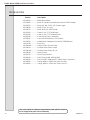
No. Part No. Description (Qty.)

vii
DUKE Model 959R Soft Serve Freezer
184981
Safety Decal Locations

viii
DUKE Model 959R Soft Serve Freezer
184981
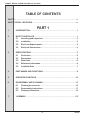
TABLE OF CONTENTS
SAFETY ............................................................................................................... ii
SAFETY DECAL LOCATIONS ............................................................................... iv
PART 1
1 INTRODUCTION .................................................................................... 1
2 NOTE TO INSTALLER ............................................................................ 1
2.1 Uncrating and Inspection............................................................. 2
2.2 Installation .................................................................................. 3
2.3 Electrical Requirements .............................................................. 3
2.4 Electrical Connections ................................................................ 4
3 SPECIFICATIONS .................................................................................. 5
3.1 Particulars ................................................................................... 5
3.2 Dimensions ................................................................................. 5
3.3 Data Plate .................................................................................... 6
3.4 Reference Information ................................................................. 6
3.5 Installatin Date ............................................................................ 7
4 PART NAMES AND FUNCTIONS ............................................................. 8
5 OPERATOR CONTROLS ...................................................................... 12
6 DISASSEMBLY AND CLEANING ........................................................... 15
6.1 Cleaning Accessories ................................................................ 16
6.2 Disassembly Instructions ........................................................... 17
6.3 Cleaning Instructions ................................................................ 19
7 ASSEMBLY ........................................................................................ 22

ix
DUKE Model 959R Soft Serve Freezer
184981
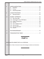
8 STARTUP INSTRUCTIONS ................................................................... 24
8.1 Sanitizing .................................................................................. 24
8.2 Priming ...................................................................................... 25
8.3 Dispensing Product ................................................................... 27
9 CLOSING PROCEDURES ..................................................................... 28
9.1 Draining Product ....................................................................... 28
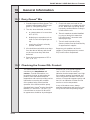
10 GENERAL INFORMATION .................................................................... 29
10.1 Dairy Queen Mix ........................................................................ 29
10.2 Checking the Frozen DQ Product. .............................................. 29
10.3 Product Temperature ................................................................. 30
10.4 Overrun ..................................................................................... 30
10.5 Overrun Measurement ............................................................... 30
10.6 Overrun Chart ........................................................................... 31
10.7 Overrun Adjustment .................................................................. 32
10.8 Rerun 32
11 ROUTINE MAINTENANCE ................................................................... 33
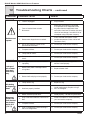
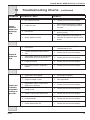
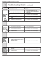
12 TROUBLESHOOTING TABLES ............................................................. 37
PART II
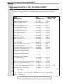
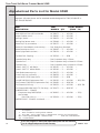
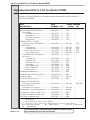
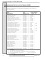
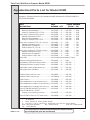
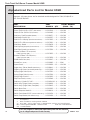
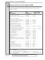
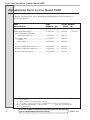
MODEL 959R REPLACEMENT PARTS w/ ILLUSTRATIONS ................................................ *
*Refer to Part II Table of Contents for help with locating part numbers and illustrations.


184981
1
DUKE Model 959R Soft Serve Freezer
2 Note to Installer
This freezer must be installed and serviced by a qualied service technician in
accordance with the installation instructions.
After installation the warranty registration card must be completed and
returned to validate warrranty.
1 Introduction
The 959R Freezer is designed to
produce DQ soft serve ice cream or DQ
frozen yogurt, with a product serving
temperature of 18 to 19ºF (-8 to -7ºC).
Use of other products in this machine is
considered misuse (see Warranty.)
This manual has been prepared to assist
in the training of personnel on the proper
operation and general maintenance of
your Duke freezer.
Your freezer will not compensate for or
correct any assembly or priming errors
made during the initial start-up. Therefore,
it is extremely important to follow the
assembly and priming procedures
detailed in this manual.
Make sure all personnel responsible for
equipment operation completely read and
understand this manual before operating
the freezer. When properly operated and
maintained, your freezer will produce a
consistent quality product.
Name ______________________
Address_____________________
____________________________
Phone_______________________
or H.C. Duke & Son, LLC, Service
Department for factory service
assistance.
Telephone: (309) 755-4553
or (800) 755-4545
Fax: (309) 755-9858
E-mail: [email protected]
If you require technical assistance, please
contact your local H.C. Duke & Son
service company:

2 184981
DUKE Model 959R Soft Serve Freezer
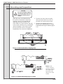
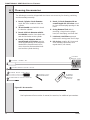
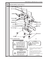
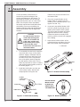
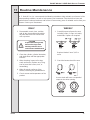
2.1 Uncrating and Inspection
Figure 2-1 Machine Bolted to Shipping Base
CAUTION
Be sure to properly support
the machine when removing
bolts and installing legs or
casters.
When the unit is received and while
the carrier is still present, inspect the
shipping carton for any damage that
may have occurred in transit. If the
SHOCKWATCH
®
label indicates red and/
or the carton is broken, torn, or punctured
note the damage on the carrier’s freight
bill and notify the carrier’s local agent
immediately, also note on the freight bill.
1. Remove the carton from the pallet,
and move the machine as close as
possible to the permanent location.
2. Remove the shipping bolts on the
bottom of the freezer (gure 2-1) and
install either the legs or casters (gure
2-2).
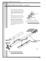
Figure 2-2 Installing Mounting Legs or Casters
NOTE: Screw
casters or legs all
the way in coupling,
then adjust out to
level side to side
with 1/4 inch slope
to front.

184981
3
DUKE Model 959R Soft Serve Freezer
2.2 Installation
1. Where codes permit, we recommend
that you install the freezer on casters
and have exible water and electrical
connections for easier service and
cleaning ability.
2. All models require a minimum 6-inch
(15cm) clearance on the rear and side
panels for adequate ventilation.
3. Water cooled will require a 1/2”
female are water inlet and water
waste connection. Both condensers
are tied together so that one water
inlet and one water waste are all
that is required. The connections
are found on the back panel and are
clearly tagged - “Water Inlet” and
“Water Waste”. A manual shut-off
valve should be installed in the water
inlet line at the time of installation. Be
sure to maintain inlet water pressure
above 35 psig and below 140 psig.
4. Place the freezer in the nal location
and level the machine by adjusting
the legs or casters so that the unit
is level side-to-side, and the front is
approximately 1/4” lower than the
rear. This will allow proper drainage of
the freezing cylinder.
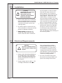
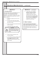
2.3 Electrical Requirements
Also, on three-phase systems,
voltage between phases must be
balanced within 2%. (More than a
6 volt difference between any two
voltage measurements at 208-230
volts indicates a possible imbalance.)
Request local power company to
correct any voltage problem.
3. An easily accessible main power
disconnect must be provided for all
poles of the wiring to the freezer.
CAUTION
To prevent accidental electrical
shock, a positive earth ground is
required.
1. Always verify electrical specications
on the data plate of each individual
freezer. Data plate specications will
always supersede the information in
this manual.
2. Supply voltage must be within + 10%
of voltage indicated on nameplate.
CAUTION
All materials and connections
must conform to local
requirements and be in
compliance with the National
Electrical Code (NEC).

4 184981
DUKE Model 959R Soft Serve Freezer
2.4 Electrical Connections
1. Double freezers with two compressors
require one power supply for each
side of the freezer. Each side of the
freezer operates independently.
2. Check the data plate for fuse
size, wire ampacity and electrical
specications.
3. Refer to the wiring diagram provided
for proper power connections.
4. Electrical connections are made in
the junction box(es) located mid-level
behind the back panel.
5. Use a exible connection when
permissible. All materials and
connections must conform to local
codes and/or the National Electrical
Code.
6. Beater shaft rotation must be
clockwise as viewed from the front of
the freezer.
CAUTION
To prevent accidental electrical
shock, a positive earth ground
is required.

184981
5
DUKE Model 959R Soft Serve Freezer
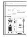
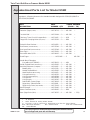
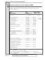
3 Specifications
Always check and verify voltage and amperage on the data plate located on the back
panel of each freezer.
MODEL 959R
3.1 Particulars
Figure 3-1
3.2 Dimensions
Width-in./cm 16/40.6
Height-in./cm 58/147.3
Depth-in./cm 36/91.4
Weight-lbs./kg 680/308.4
Compressor* 3 H.P. /11,000
(BTUH)
2.2 kw (Motor)
3.2 kw (Cooling)
Beater Motor 2 H.P/1.5 kw
Refrigerant 404a
Charge (Water Cooled) 3.75
lb/1.70 kg
Cylinder (Two) 4 Qts./3.8 Liters
(each)
*Contact factory for other voltages.

6 184981
DUKE Model 959R Soft Serve Freezer
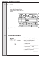
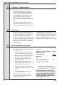
3.3 Data Plate
The data plate provides important
information that the operator should
record and have available for parts
ordering, warranty inquiries, and service
requests.
Figure 3-2 Data Plate
Write in
Reference
Information HERE!
3.4 Reference Information
Fill in the following information below as
soon as you receive the 959R. (The item
numbers—encircled, below—correspond
with the callout numbers above.)
IMPORTANT: Complete for reference:
1.) Model Number:___________________
2.) Serial Number:___________________
3.) Electrical Spec: Voltage ________
Phase _______ Hertz _____________
4.) Minimum Circuit Ampacity:_________
5.) Maximum Fuse Size: _____________

184981
7
DUKE Model 959R Soft Serve Freezer
3.5 Installation Date
Fill in the date of installation, and the name, address, and phone number of the
installer in the space provided below. This information will be needed when ordering
parts or service for your freezer.
Installation Date: ______________________________
Installed by: ______________________________
Address: ______________________________
______________________________
Phone : ______________________________

8 184981
DUKE Model 959R Soft Serve Freezer
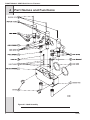
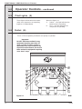
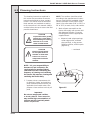
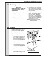
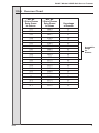
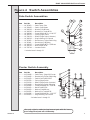
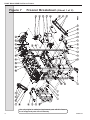
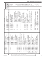
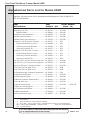
4 Part Names and Functions
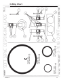
Figure 4-1 Head Assembly

184981
9
DUKE Model 959R Soft Serve Freezer
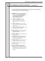
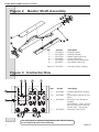
1.) HEAD: Encloses the freezing cylinder
and provides an opening for product to
be dispensed. NOTE: Beater motors
will not operate with the head
removed from the freezer.
2.) SPIGOT - ASSEMBLY: Seals the
product opening in the head when
closed. Allows product to ow when
open.
3.) O-RING - SPIGOT: Seals the spigot in
the head. Must be lubricated to seal and
slide properly.
4.) O-RING - SPIGOT EXTENSION: Holds
the extension on to the spigot.
5.) ROD - SPIGOT: Starts the freezer when
dispensing. Must be in place before
freezer will operate.
6.) KNOB - HAND: Secures the head to the
freezing cylinder.
7.) EXTENSION - SPIGOT: (Accessory)
Extends the product opening down to
aid in cake-making process.
8.) O-RING - HEAD: Seals the head to the
freezing cylinder. Must be lubricated.
9.) O-RING - PLUG: Seals the air bleed
plug in the head.
10.) PLUG - AIR BLEED: (BLEEDER-
ASSY)
: Seals the air bleed opening in
the head when closed. Allows excess air
to be removed from the cylinder when
priming.
4 Part Names and Functions – continued
The following descriptions apply to gure 4-1. The number preceding the part
name corresponds to the number in the gure.

10 184981
DUKE Model 959R Soft Serve Freezer
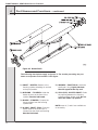
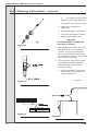
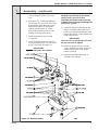
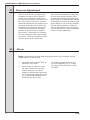
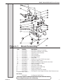
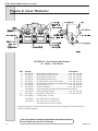
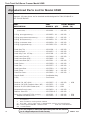
4 Part Names and Functions – continued
Figure 4-2 Beater Shaft
The following descriptions apply to gure 4-2. The number preceding the part
name corresponds to the number in the gure.
1.) SHAFT - BEATER: Rotates in the
freezing cylinder, blending air and mix
as it ejects product.
2.) BUSHING - CYLINDER: Holds the
beater in place at the front of the
cylinder. Must be lubricated.
3.) BLADE - SCRAPER: Scrapes the
frozen product from the freezing
cylinder wall.
4.) O-RING - SHAFT SEAL: Seals the
beater shaft to the shaft seal. Is
inserted into the shaft seal bushing.
Must be lubricated.
5.) WASHER - SHAFT SEAL: Holds the
shaft seal o-ring. Lightly lubricate
the side opposite the cup seal.
6.) SEAL(CUP) - BEATER SHAFT: Seals
the opening between the freezing
cylinder and the beater shaft. Do not
lubricate rubber cup portion.
NOTE: Items 4, 5, and 6 are available as
an assembly.
Page is loading ...
Page is loading ...
Page is loading ...
Page is loading ...
Page is loading ...
Page is loading ...
Page is loading ...
Page is loading ...
Page is loading ...
Page is loading ...
Page is loading ...
Page is loading ...
Page is loading ...
Page is loading ...
Page is loading ...
Page is loading ...
Page is loading ...
Page is loading ...
Page is loading ...
Page is loading ...
Page is loading ...
Page is loading ...
Page is loading ...
Page is loading ...
Page is loading ...
Page is loading ...
Page is loading ...
Page is loading ...
Page is loading ...
Page is loading ...
Page is loading ...
Page is loading ...
Page is loading ...
Page is loading ...
Page is loading ...
Page is loading ...
Page is loading ...
Page is loading ...
Page is loading ...
Page is loading ...
Page is loading ...
Page is loading ...
Page is loading ...
Page is loading ...
Page is loading ...
Page is loading ...
Page is loading ...
Page is loading ...
Page is loading ...
Page is loading ...
Page is loading ...
Page is loading ...
Page is loading ...
Page is loading ...
Page is loading ...
Page is loading ...
Page is loading ...
Page is loading ...
Page is loading ...
-
 1
1
-
 2
2
-
 3
3
-
 4
4
-
 5
5
-
 6
6
-
 7
7
-
 8
8
-
 9
9
-
 10
10
-
 11
11
-
 12
12
-
 13
13
-
 14
14
-
 15
15
-
 16
16
-
 17
17
-
 18
18
-
 19
19
-
 20
20
-
 21
21
-
 22
22
-
 23
23
-
 24
24
-
 25
25
-
 26
26
-
 27
27
-
 28
28
-
 29
29
-
 30
30
-
 31
31
-
 32
32
-
 33
33
-
 34
34
-
 35
35
-
 36
36
-
 37
37
-
 38
38
-
 39
39
-
 40
40
-
 41
41
-
 42
42
-
 43
43
-
 44
44
-
 45
45
-
 46
46
-
 47
47
-
 48
48
-
 49
49
-
 50
50
-
 51
51
-
 52
52
-
 53
53
-
 54
54
-
 55
55
-
 56
56
-
 57
57
-
 58
58
-
 59
59
-
 60
60
-
 61
61
-
 62
62
-
 63
63
-
 64
64
-
 65
65
-
 66
66
-
 67
67
-
 68
68
-
 69
69
-
 70
70
-
 71
71
-
 72
72
-
 73
73
-
 74
74
-
 75
75
-
 76
76
-
 77
77
-
 78
78
-
 79
79


Ask a question and I''ll find the answer in the document
Finding information in a document is now easier with AI
Related papers
Other documents
-
 Dwell Home Inc HB-KS-FQ-M201 Installation guide
-
Indesit FFUXL4D K User guide
-
Holley 12-126 Operating instructions
-
ARC RCL-95 LED Searchlight Template
-
KTM 200 DUKE 2013 COL User manual
-
Stoelting U3-02 User manual
-
-
 HART HPSV50 Owner's manual
-
 Coldelite UC 511 G User manual
-
Manitowoc Ice SF0400 SN0450 SF0600 SN650 SF0900 SN950 1ph Product information


