Page is loading ...

ID Repeater Daughter Board 600-1031
Installation Instructions
Description
The ID Repeater Daughter Board mounts directly onto any
frequency OEM transceiver module and converts the
transceiver into a repeater. The purpose of the repeater is to
receive and retransmit signals from wireless sensors, wireless
touchpads, and other repeaters.
Installation guidelines
Observe the following guidelines when installing the ID
Repeater Daughter Board and OEM transceiver module:
• Allow at least 9 inches (22.9 cm) of clearance above the
enclosure for the antennas.
• Avoid mounting locations that expose the module to
moisture.
• Avoid areas with excessive metal or electrical wiring
including furnace and utility rooms. If unavoidable, mount
on or near metal with the antenna extending above the
metallic surfaces as shown in Figure 1 below.
Figure 1: Mounting on or near metal
Metal
Metal
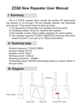
Installation
To mount the ID Repeater Daughter Board, do the following:
1. Insert the plastic standoffs supplied with the daughter
board into the standoff holes (Figure 2 below) on the
dau
ghter board.
Figure 2: ID repeater daughter board
DIP switches
Standoff hole
ON
ON
1 2 3 4 5 6 7 8
12345678
LEDs
Standoff hole
Caution: You must be free of static electricity before handling
circuit boards. Wear a grounding strap or touch a bare metal
surface to discharge static electricity.
2. Mount the ID Repeater Daughter Board onto the OEM
transceiver module as shown in Figure 3 below.
Figure 3: ID Repeater Daughter Board mounted on the OEM
transceiver
OEM transceiver LEDs
ID Repeater Daughter Board
OEM transceiver module
ON
ON
1 2 3 4 5 6 7 8
12345678
To mount the 600-1029 enclosure, follow the installation
instruction provided with the enclosure.
To mount the OEM transceiver module onto the back plate of
the 600-1029 enclosure (Figure 4 on page 2), do the following:
1.
Insert the antennas into the antenna shrouds.
2. Gently slide the top of the OEM transceiver module under
the two top latches.
3. Snap the OEM transceiver module in at the bottom latch to
secure it in place.
P/N 466-22
02 • REV C • January 2011 1

Figure 4: OEM
transceiver module mounted in the 600-1029
enclosure
Antenna shrouds
Top latches
OEM tranceiver module
Bottom latch
2 mm power jack
Terminal block
600-1029 enclosure
ON
ON
1 2 3 4 5 6 7 8
1 2 3 4 5 6 7
8
4. Connect DC power to the OEM transceiver module using
a 2 mm power jack (center positive), or connect flyleads to
the terminal block as labeled on the board.
LED operation
Table 1 below shows the LED indications for the OEM
transceiver module.
Table 1: OEM transceiver module LED indications
Indication Green LED Red LED
Powered up On Off
Communication with daughter board On Flashing
Valid packet received On flash off Off or flashing
Table 2 below shows the LED indications for the ID Repeater
Daughter Board.
Table 2: IRepeater Daughter Board LED indications
Indication Green LED Green LED Red LED
Power up Power up Flashes
version*
On
Run On steady Off
Run error Off On
Run Packet in to be
repeated
One flash off Off
Enroll Long flashes Off
Enroll Pocket in, sensor
enrolled
Long flashes One long flash
Enroll Pocket in, repeater
enrolled
Long flashes Two long
flashes
Enroll Tamper hit, sensor
removed
Long flashes One long flash
Enroll Tamper hit,
repeater removed
Long flashes Two long
flashes
Delete Long flashes Quick flashes
Delete Packet in, sensor
removed
Long flashes One long flash
Delete Packet in, repeater
removed
Long flashes Two long
flashes
Delete all Quick flashes
Delete all Tamper hit, all
removed
Long flashes Long flashes
* When flashing the version, a long flash indicates a 1 and a short
flash indicates a 0.
Modes of operation
The unit has the following modes of operation:
• Smart mode - The ID Repeater Daughter Board only
retransmits signals from sensors and repeaters that have
been enrolled into memory (up to 127 sensors and 4
repeaters). Smart mode is the recommended mode of
operation and is enabled when the repeater number is set
to a non-zero number.
• Dumb mode - The repeater retransmits signals heard
from any sensor, but does not repeat signals from other
repeaters. You can only have one dumb mode repeater
per installation.
Configuration
Table 3 below shows how to configure the modes of operation.
Table 3: Repeater configuration
DIP switches
Action OEM tamper
1 2 3 4 5 6 7 8
Run mode N/A X X 0 Repeater number
Program mode Open X X 1 Repeater number
Enroll mode Open 0 0 1 Repeater number
Delete last device
enrolled*
Press to
delete
0 0 1 Repeater number
Delete mode Open 0 1 1 Repeater number
Delete all Press to
delete
1 0 1 Repeater number
Disable unlearned
panic repeat
Press to
disable
1 1 1 0 0 0 1 0
Enable unlearned
panic repeat
Press to
enable
1 1 1 0 0 0 1 1
63-bit mode Press to set
mode
1 1 1 0 0 1 0 0
63/80-bit mode Press to set
mode
1 1 1 0 0 1 0 1
*Only deletes device during current enrollment session.
Selecting 63-bit only - Only 63-bit signals are transmitted and
the repeater status is reported via 63-bit packets. This mode
can be used while operating in either smart or dumb modes.
Selecting 63/80-bit - 63-bit and 80-bit signals are
retransmitted and the repeater status is reported via 80-bit
packets. This mode can only be used in conjunction with smart
mode. Refer to the sensor’s installation manual to determine if
63 or 80-bit format is appropriate for a particular sensor.
2 ID Repeate
r Daughter Board 600-1031 Installation Instructions

Setting the repeater number
By setting a repeater number to a unique, non-zero number
using DIP switches 4 to 8, you enable the repeater for smart
mode operation (see Table 4 below).
Note: When the repeater is operated in 63/80-bit mode, the
repeater number is limited to 1 through 15.
Table 4: Repeater number DIP switch settings
DIP switches
Repeater
number
4 5 6 7 9
0 0 0 0 0 0
1 0 0 0 0 1
2 0 0 0 1 0
3 0 0 0 1 1
4 0 0 1 0 0
5 0 0 1 0 1
6 0 0 1 1 0
7 0 0 1 1 1
8 0 1 0 0 0
9 0 1 0 0 1
10 0 1 0 1 0
11 0 1 0 1 1
12 0 1 1 0 0
13 0 1 1 0 1
14 0 1 1 1 0
15 0 1 1 1 1
16* 1 0 0 0 0
17* 1 0 0 0 1
18* 1 0 0 1 0
19* 1 0 0 1 1
20* 1 0 1 0 0
21* 1 0 1 0 1
22* 1 0 1 1 0
23* 1 0 1 1 1
24* 1 1 0 0 0
25* 1 1 0 0 1
26* 1 1 0 1 0
27* 1 1 0 1 1
28* 1 1 1 0 0
29* 1 1 1 0 1
30* 1 1 1 1 0
31* 1 1 1 1 1
Note: *Not a valid repeater number when operated in 63/80-bit mode.
Note: 1 = DIP switch up (On), 0 = DIP switch down (Off)
Sensor/repeater enrollment
To enroll the sensor or repeater, do the following:
1. Place the repeater into enroll mode by placing DIP switch
3 into the on position (Table 3 on page 2). The ID
Rep
eater Daughter Board’s LEDs flash to indicate the
mode has been entered. (Table 2 on page 2).
2. Trip the enrollment mechanism for each sensor/repeater
(Table 5 below). The ID Repeater Daughter Board’s red
LED flash
es to indicate successful enrollment (Table 2 on
pag
e 2).
Note:
The last sensor/repeater enrolled may be deleted by
pressing the OEM receiver’s tamper switch. Other
repeaters can only be enrolled if their repeater number is
greater than the repeater number of the enroller.
3. Return all ID Repeater Daughter Board DIP switches to
the run mode positions (Table 3 on page 2).
Delete sensors/repeaters
To delete sensors or repeaters, do the following:
1. Place the repeater into delete mode by placing DIP
switches 2 and 3 into the on position (Table 3 on page 2).
T
he ID Repeater Daughter Board’s LEDs flash to indicate
the mode has been entered (Table 2 on page 2).
2. Trip the enrollment mechanism for each sensor/repeater
(Table 5 below). The ID Repeater Daughter Board’s red
LED flash
es to indicate the sensor/repeater was
successfully deleted (Table 2 on page 2).
Delete all
To clear the memory of all enrollments, do the following:
1. Place the repeater into delete all mode by placing DIP
switches 1 and 3 into the on position (Table 3 on page 2).
T
he ID Repeater Daughter Board’s LEDs flash to indicate
the mode has been entered (Table 2 on page 2).
2. Press and release the OEM transceiver module’s tamper
switch. The ID Repeater Daughter Board’s red LED
flashes to indicate the memory was cleared (Table 2 on
pag
e 2).
Table 5: Enrollment mechanism
Transmitter Action
Sensors Remove cover/base or press and release
tamper switch.
Keychain touchpad Press lock and unlock buttons simultaneously.
Other touchpad Bypass button.
Receiver Remove cover or press and release tamper
switch.
Testing
The receive and transmit tests should be done prior to
permanently mounting the repeater, but after programming is
completed.
Note: It takes two people to do the following tests due to the
distance between devices.
ID Repeate
r Daughter Board 600-1031 Installation Instructions 3

4 ID Repeater Daughter Board 600-1031 Installation Instructions
Receive test
Table 8: ID Repeater Daughter Board troubleshooting
Problem Action
ID Repeater
Daughter Board’s
green and red LEDs
are off
1. Check that the transformer is plugged in.
2. Check the transformer to module wiring.
3. Check the ID Repeater Daughter Board
mounting.
ID Repeater
Daughter Board’s
green LED is off and
red LED flashes
slowly
1. Disconnect the transformer, verify the
daughter board mounting and reconnect the
transformer.
2. The ID Repeater Daughter Board is set to
63/ 80 and the repeater board’s number is set
to zero. Set the repeater board to a non-zero
number.
To test that the repeater is receiving information, do the
following:
1. Force each device that is intended to operate with the
repeater to transmit. The green LED on the OEM
transceiver module located directly below the terminal
block will flash for each packet received. The ID Repeater
Daughter Board’s green LED will also flash if:
• The ID Repeater Daughter Board is in the dumb
mode, or
• The ID Repeater Daughter Board is in the smart
mode and the sensor/repeater tripped is enrolled.
2. Verify that at least 7 of 8 (14 of 16) of the packets are
received. The number of packets may vary depending on
the type of device (Table 6 below).
Specifications
Transmit test
To test that the repeater is transmitting information, do the
following:
1. Force the repeater to transmit by either pressing the
tamper switch or tripping an enrolled device.
2. Verify that at least 7 of 8 (14 of 16) of the packets are
received by the panel or another repeater. The number of
packets may vary depending on the type of devices
(Table 6 below).
Table 6: Number of packets sent per device type
Device Trigger Number of
packets
Door/window sensor Remove magnet cover 8
Keychain touchpad Press lock and unlock
simultaneously
8
Other touchpads Press and hold emergency
buttons
8
Panic button Press and hold 5 seconds, then
release
16
PIR motion sensor Remove from mounting plate 8
Repeater Press and hold tamper for 5
seconds, then release
16
Smoke sensor Press and hold test button for 20
seconds
8
Compatibility OEM transceivers and wireless transmitters
Power requirements Power supplied by OEM transceiver module (
see appropriate OEM transceiver manual for
details)
Wireless signal range See appropriate OEM transceiver manual
Operating temperature 32 to 120°F (0 to 49°C)
Storage temperature -30 to 140°F (-34 to 60°C)
Max. relative humidity 85% noncondensing
Dimensions (LxWxD) 6.5 in. x 4.6 in. x 1.25 in. (16.5 cm x 11.7 cm
x 3.2 cm) excluding antennas
Regulatory information
Manufacturer UTC Fire & Security Americas Corporation, Inc.
1275 Red Fox Rd., Arden Hills, MN 55112-6943,
USA
FCC compliance:
This device complies with FCC Rules Part 15. Operation is subject to
the following two conditions:
1. This device may not cause harmful interference.
2. This device must accept any interference that may be received,
including interference that may cause undesired operation.
Changes or modifications not expressly approved by UTC Fire &
Security can void the user’s authority to operate the equipment.
Certification
European Union directives:
We declare under our sole responsibility that this product is in
conformity with Directive 93/68/EEC (Marking) and/or complies to the
essential requirements and all other relevant provisions of the
1999/5/EC (R&TTE) based on test results using (non) harmonized
standards in accordance with the Directives mentioned.
Troubleshooting
The following tables give troubleshooting suggestions for the
OEM transceiver module and the ID Repeater Daughter Board.
Table 7: OEM transceiver module troubleshooting
Contact information
Problem A
ction
OEM transceiver
module’s green and
red LEDs are off
1. Check that the transformer is plugged in.
2. Check the transformer to module wiring.
OEM transceiver
modules’ green LED is
on and red LED is off
Check the ID Repeater Daughter Board
mounting.
For contact information, see www.utcfireandsecurity.com or
www.interlogix.com.
For technical support, toll-free: 888.437.3287 in the US
including Alaska, Hawaii, Puerto Rico, and Canada. Outside
the tool-free area, contact your dealer.
Copyright © 2011 Interlogix, a UTC Fire & Security Company.
All rights reserved.
/