Page is loading ...

Rev. 0.2 11/14 Copyright © 2014 by Silicon Laboratories ToolStick-C8051F530ADC
ToolStick-F530ADC
TOOLSTICK C8051F530A DAUGHTER CARD USER’S GUIDE
1. Handling Recommendations
To enable development, the ToolStick Base Adapter and daughter cards are distributed without any protective
plastics. To prevent damage to the devices and/or the host PC, please take into consideration the following
recommendations when using the ToolStick:
Never connect or disconnect a daughter card to or from the ToolStick Base Adapter while the Base Adapter
is connected to a PC.
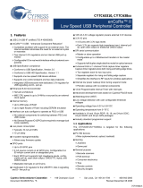
Always connect and disconnect the ToolStick Base Adapter from the PC by holding the edges of the boards
as shown in Figure 1.
Figure 1. Proper Method of Holding the ToolStick
Avoid directly touching any of the other components.
Figure 2. Improper Method of Holding the ToolStick
Manipulate mechanical devices on the daughter cards, such as potentiometers, with care to prevent the
Base Adapter or daughter card from accidentally dislodging from their sockets.

ToolStick-F530ADC
2 Rev. 0.2
2. Contents
The ToolStick-F530ADC kit contains the following items:
ToolStick C8051F530A Daughter Card
A ToolStick daughter card requires a ToolStick Base Adapter to communicate with the PC. ToolStick Base Adapters
can be purchased at www.silabs.com/toolstick.
3. ToolStick Overview
The purpose of the ToolStick is to provide a development and demonstration platform for Silicon Laboratories
microcontrollers and to demonstrate the Silicon Laboratories software tools, including the Integrated Development
Environment (IDE).
The ToolStick development platform consists of two components: the ToolStick Base Adapter and a daughter card.
The ToolStick Base Adapter provides a USB debug interface and data communications path between a Windows
PC and a target microcontroller.
The C8051F530A Daughter Card includes a pair of LEDs, a potentiometer, an LIN transceiver, a connector block
for the LIN signals, a switch connected to a GPIO, and a small prototyping area that provides access to all of the
pins of the device. This prototyping area can be used to connect additional hardware to the microcontroller and use
the daughter card as a development platform. The board also includes a LIN transceiver and a circuit that doubles
the +5 V from the USB interface to generate the 10 V supply needed for LIN communication. The terminal block,
J2, allows developers to use an external LIN supply voltage instead of the voltage generated on the board.
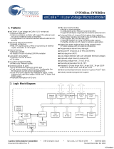
Figure 3 shows the ToolStick C8051F530A Daughter Card and identifies the various components.
Figure 3. ToolStick C8051F530A Daughter Card
S1
R4
F530A
U2
D1
D2
TOOLSTICK F530A DC
PWR
VDD
GND
Px.0 Px.1 Px.2 Px.3 Px.4 Px.5 Px.6 Px.7
P1
P0
J2
P1.5
P1.4
GND
LIN
+12V
C8051F530A
Power LED
P1.3 LED
P1.5 Potentiometer P1.4 Switch
LIN Interface
Full Pin
access

ToolStick-F530ADC
Rev. 0.2 3
4. Getting Started
The necessary software to download, debug, and communicate with the target microcontroller must be
downloaded from www.silabs.com/toolstick. The following software is necessary to build a project, download code
to, and communicate with the target microcontroller:
Simplicity Studio
Keil C51 Tools
ToolStick Development Tools
The software described above is provided in the Simplicity Studio and 8-bit microcontroller studio download
packages. The ToolStick Development Tools selection includes example code specifically for the ToolStick
daughter card, documentation including user’s guides and data sheets, and the ToolStick Terminal application.
After downloading and installing these packages, see the following sections for information regarding the software
and running one of the demo applications.
5. Software Overview
Simplicity Studio greatly reduces development time and complexity with Silicon Labs EFM32 and 8051 MCU
products by providing a high-powered IDE, tools for hardware configuration, and links to helpful resources, all in
one place.
Once Simplicity Studio is installed, the application itself can be used to install additional software and
documentation components to aid in the development and evaluation process.
Figure 4. Simplicity Studio

ToolStick-F530ADC
4 Rev. 0.2
The following Simplicity Studio components are required for the C8051F530 ToolStick Starter Kit:
8051 Products Part Support
Simplicity Developer Platform
Download and install Simplicity Studio from www.silabs.com/simplicity-studio. Once installed, run Simplicity Studio
by selecting Start
Silicon LabsSimplicity StudioSimplicity Studio from the start menu or by clicking the
Simplicity Studio shortcut on the desktop. Follow the instructions to install the software and click Simplicity IDE
to launch the IDE.
The first time the project creation wizard runs, the Setup Environment wizard will guide the user through the
process of configuring the build tools and SDK selection.
In the Part Selection step of the wizard, select from the list of installed parts only the parts to use during
development. Choosing parts and families in this step affects the displayed or filtered parts in the later device
selection menus. Choose the C8051F53x/52x family by checking the C8051F53x/52x check box. Modify the part
selection at any time by accessing the Part Management dialog from the Window
PreferencesSimplicity
Studio
Part Management menu item.
Simplicity Studio can detect if certain toolchains are not activated. If the Licensing Helper is displayed after
completing the Setup Environment wizard, follow the instructions to activate the toolchain.
5.1. Running the Features Demo
To create a project for the Features Demo example, perform the following steps:
1. Click the Software Examples tile from the Simplicity Studio home screen.
2. In the Kit drop-down, select C8051F530A ToolStick Daughter Card; in the Part drop-down, select
C8051F530, and in the SDK drop-down, select the desired SDK. Click Next.
3. Select Example, and click Next.
4. Under C8051F530A ToolStick Daughter Card, select TS F52x-53x FeaturesDemo, and click Finish.
5. Click on the project in the Project Explorer, and click Build (the hammer icon in the top bar). Alternatively,
go to Project
Build Project.
6. Click Debug to download the project to the hardware and start a debug session.
7. Follow the instructions at the top of the example file to run the demo.
8. Press the Resume button to start the code running.
9. Press the Suspend button to stop the code.
10. Press the Reset the device button to reset the target MCU.
11. Press the Disconnect button to return to the development perspective.

ToolStick-F530ADC
Rev. 0.2 5
5.2. Simplicity Studio Help
Simplicity Studio includes detailed help information and device documentation within the tool. The help contains
descriptions for each dialog window. To view the documentation for a dialog, click the question mark icon in the
window:
This will open a pane specific to the dialog with additional details.
The documentation within the tool can also be viewed by going to Help
Help Contents or HelpSearch.
5.3. Configuration Wizard 2
The Configuration Wizard 2 is a code generation tool for all of the Silicon Laboratories devices. Code is generated
through the use of dialog boxes for each of the device's peripherals.
Figure 5. Configuration Wizard 2 Utility
The Configuration Wizard 2 utility helps accelerate development by automatically generating initialization source
code to configure and enable the on-chip resources needed by most design projects. In just a few steps, the wizard
creates complete startup code for a specific Silicon Laboratories MCU. The program is configurable to provide the
output in C or assembly.
For more information, refer to the Configuration Wizard 2 documentation. The documentation and software
available from the Downloads web page (www.silabs.com/mcudownloads).

ToolStick-F530ADC
6 Rev. 0.2
5.4. ToolStick Terminal
The ToolStick Terminal program provides the standard terminal interface to the target microcontroller's UART.
However, instead of requiring the usual RS-232 and COM port connection, ToolStick Terminal uses the USB
interface of the ToolStick Base Adapter to provide the same functionality. The software is available on the ToolStick
web page (www.silabs.com/toolstick).
In addition to the standard terminal functions (send file, receive file, change baud rate), two GPIO pins on the target
microcontroller can be controlled using the Terminal for either RTS/CTS handshaking or software-configurable
purposes.
To use the ToolStick Terminal program:
1. Download an example to the ToolStick device that uses UART communication. One example of this type is
the TS F52x-53x FeaturesDemo example from the Simplicity Studio example project creation wizard.
2. Disconnect from the device in the Simplicity IDE. The IDE and the ToolStick Terminal cannot communicate
with the daughter card simultaneously.
3.
Open ToolStick Terminal from the
Start
Programs
Silicon Labs
menu.
4. In the top, left-hand corner of the Terminal application, available devices are shown in the drop-down
Connection menu. Click Connect to connect to the device.
5. If using the TS F52x-53x FeaturesDemo example, text printed from the device will appear in the Receive
Data window.
6. Rotate the potentiometer on the board to change the blink rate or brightness of the LED.
In addition to the standard two UART pins (TX and RX), there are two GPIO/UART handshaking pins on the
ToolStick Base Adapter that are connected to two port pins on the target microcontroller. ToolStick Terminal is used
to configure and read/write these pins. Under the Pin State Configuration area in ToolStick Terminal, select the
desired state from the drop-down menu, and click the Set Selected Pin States button.
The firmware on the C8051F530 target microcontroller does not need to be customized to use the UART and
communicate with ToolStick Terminal. The firmware on the microcontroller should write to the UART as it would in
any standard application, and all of the translation is handled by the ToolStick Base Adapter.

ToolStick-F530ADC
Rev. 0.2 7
6. Using the C8051F530A Daughter Card as a Development Platform
The prototyping area on the ToolStick C8051F530A Daughter Card makes it easy to interface to external hardware.
All of the digital I/O pins are available, so it possible to create a complete system.
6.1. C8051F530A Pin Connections
It is important to note that if external hardware is being added, some of the existing components on the board can
interfere with the signaling. The following is a list of port pins on the C8051F530A that are connected to other
components:
P0.4, P0.5-These pins are connected directly to the ToolStick Base Adapter for UART communication.
P1.1, P1.2-These pins are connected directly to the ToolStick Base Adapter's GPIO pins. By default, these
GPIO pins on the Base Adapter are high-impedance pins, so they will not affect any signaling. Configuring
these pins on the Base Adapter to output pin or handshaking pins could affect signaling.
P1.3-This pin is connected to the cathode of the green LED on the daughter card. The LED or the R2
resistor can be removed to disconnect the LED from the pin.
P1.4-This pin is connected to the "S1" switch. The switch can be removed to disconnect them from the pin.
P1.5-This pin is connected to the output of the potentiometer. R5 (a 0 resistor) can be removed to
disconnect the potentiometer from the pin.
See “7. C8051F530A Daughter Card Schematic” for more information.
6.2. C2 Pin Sharing
On the C8051F530A, the debug pins, C2CK, and C2D, are shared with the pins, /RST and P0.6, respectively. The
daughter card includes the resistors necessary to enable pin sharing, which allow the /RST and P0.6 pins to be
used normally while simultaneously debugging the device. See "AN124: Pin Sharing Techniques for the C2
Interface" at www.silabs.com for more information regarding pin sharing.

ToolStick-F530ADC
8 Rev. 0.2
7. C8051F530A Daughter Card Schematic
PWR
TOP SIDEBOTTOM SIDE
CARD EDGE CONNECTOR
P0 P1
(XTAL1)
(RX)
(TX)
(XTAL2)
(RTS)
(CTS)
(VREF_TH8080-TXD)
DEBUG CIRCUIT
(TH8080-RXD)
(TH8080-TXD)
(TH8080-RXD)
+12V
LIN
GND
(LED-GREEN)
(PUSHBUTTON)
(POTENTIOMETER)
1
GND
2
VDD(3.3V)
3
VBUS(5V)
4
VIO(IN)
5
TDI_C2CK
6
TCK_C2D
7
TDO_C2DPS
8
TDO_C2CKPS
9
TSTERMINAL_TX
10
TSTERMINAL_RX
11
GPIO0_RTS
12
GPIO1_CTS
13
SUSPEND(OUT)
14
VPPCTL(OUT)
J1
EDGE-MEC1-108-02-F-D-EM2
RF1
RUBBER_FOOT
RF2
RUBBER_FOOT
1
2
D1
RED
TP4
TP5
TP6
TP7
TP8
TP9
TP10
TP11
TP12
TP13
TP14
TP15
TP16
TP17
TP18
TP19
TP20
TP21
J2-1
J2-2
J2-3
1
2
3
D3
MMBZ27VCLT1G
1
RXD
2
NSLP
3
NWAKE
4
TXD
5
GND
6
LIN
7
BAT
8
INH
U3
TJA1020TD
R8
10
C5
180pF
X7R
C6
4.7uF
TANT
16V
C7
10nF
X7R
R9
22K
R10
22K
1
A1
2
A2
3
C
D4
MMBD1404A
R11
0.0
D5
MBR0520L
1
V+
2
GND
3
CAP-
4
SD
5
VOUT
6
CAP+
U4
LM2765
C8
3.3uF
TANT
16V
C9
3.3uF
TANT
16V
FI1
FIDUCIAL
FI2
FIDUCIAL
TP1 TP2
TP22 TP23
S1
D2
GREEN
R4
10K
R5
0.0
R3
0.0
R6
1K
R7
1K
1
RST/C2CK
2
P0.0/VREF
3
GND
4
VDD
5
VREGIN
6
P1.7
7
P1.6
8
P1.5
9
P1.4
10
P1.3
11
CNVSTR/P1.2
12
P1.1
13
XTAL2/P1.0
14
XTAL1/P0.7
15
C2D/P0.6
16
RX/P0.5
17
TX/P0.4
18
P0.3
19
P0.2
20
P0.1
21
GND_PLANE
U2
C8051F530A_QFN20
C1
0.1UF
X7R
C2
1.0UF
X7R
C4
1.0UF
X7R
C3
0.1UF
X7R
R2
680
R1
680
R12 1K
TP3
R13 22K
GND
VBUS
C2CK
P0.5
P1.1 P1.2
P0.4
C2D
P0.1
P0.2
P0.3
P0.4
P0.5
P0.6
P0.7
P1.0
P1.1
P1.2
P1.3
P1.4
P1.5
P1.6
P1.7
/RST
C2D
C2CK
GND
P0.0
P0.1
VBUS
10VVBUS
10V
VBUS VREGOUT
VDD_IN
P1.5
VREGOUT
P1.4
P0.6
C2D C2D
VBUS
C2CK C2CK
VBUSVREGOUT
P1.3
VBUS
P0.0
C2CK
P0.1
P0.2
P1.7
P1.6
P1.5 P1.4
P1.3
P1.2
P1.1
P1.0
P0.7
C2D
P0.5
P0.4
P0.3
/RST
P0.0
GND
Figure 6. C8051F530A Daughter Card Schematic


Disclaimer
Silicon Laboratories intends to provide customers with the latest, accurate, and in-depth documentation of all peripherals and modules available for system and software implementers
using or intending to use the Silicon Laboratories products. Characterization data, available modules and peripherals, memory sizes and memory addresses refer to each specific
device, and "Typical" parameters provided can and do vary in different applications. Application examples described herein are for illustrative purposes only. Silicon Laboratories
reserves the right to make changes without further notice and limitation to product information, specifications, and descriptions herein, and does not give warranties as to the accuracy
or completeness of the included information. Silicon Laboratories shall have no liability for the consequences of use of the information supplied herein. This document does not imply
or express copyright licenses granted hereunder to design or fabricate any integrated circuits. The products must not be used within any Life Support System without the specific
written consent of Silicon Laboratories. A "Life Support System" is any product or system intended to support or sustain life and/or health, which, if it fails, can be reasonably expected
to result in significant personal injury or death. Silicon Laboratories products are generally not intended for military applications. Silicon Laboratories products shall under no
circumstances be used in weapons of mass destruction including (but not limited to) nuclear, biological or chemical weapons, or missiles capable of delivering such weapons.
Trademark Information
Silicon Laboratories Inc., Silicon Laboratories, Silicon Labs, SiLabs and the Silicon Labs logo, CMEMS®, EFM, EFM32, EFR, Energy Micro, Energy Micro logo and combinations
thereof, "the world’s most energy friendly microcontrollers", Ember®, EZLink®, EZMac®, EZRadio®, EZRadioPRO®, DSPLL®, ISOmodem ®, Precision32®, ProSLIC®, SiPHY®,
USBXpress® and others are trademarks or registered trademarks of Silicon Laboratories Inc. ARM, CORTEX, Cortex-M3 and THUMB are trademarks or registered trademarks of
ARM Holdings. Keil is a registered trademark of ARM Limited. All other products or brand names mentioned herein are trademarks of their respective holders.
http://www.silabs.com
Silicon Laboratories Inc.
400 West Cesar Chavez
Austin, TX 78701
USA
Simplicity Studio
One-click access to MCU and
wireless tools, documentation,
software, source code libraries &
more. Available for Windows,
Mac and Linux!
IoT Portfolio
www.silabs.com/IoT
SW/HW
www.silabs.com/simplicity
Quality
www.silabs.com/quality
Support and Community
community.silabs.com
/