Whirlpool AKR 666 IX Program Chart

Category
Cooker hoods
Type
Program Chart

This manual is also suitable for

5019 318 33190
INSTALLATION DATA SHEET
Minimum height above cooker: 50 cm (electric cookers), 65 cm (gas, gas oil or coal cookers). If the
installation instructions for a gas cooker specify a greater distance, then this distance must be
observed. To install, follow steps (1
Ö
2
Ö
3
Ö
.....).
Do not connect the hood to the electrical power supply until installation is completed. Warning! The
exhaust pipe and clamps are not supplied and must be bought separately.
GB
31833190GB.fm Page 1 Wednesday, December 21, 2005 3:36 PM
5019 318 33190
a
a
a
31833190GB.fm Page 2 Wednesday, December 21, 2005 3:36 PM
5019 318 33190
Remove the perimeter extraction panel (if relevant) and the grease filter/s.
Pre-assemble the steam deflector on the motor assembly (if relevant): (
a.
) fit the steam deflector to the rails of the motor assembly (remove
the two travel stop screws from the steam deflector if necessary), (
b.
) connect up the control panel and the lamps, (
c.
) fix in place with the 14
screws (max).
1.
Mark a line on the wall right up to the ceiling, corresponding to the centre-line of the hood.
2.
Apply the drilling template to the wall: Align the vertical centre-line on the drilling template with the centre-line drawn on the wall. The
template's bottom edge represents the bottom edge of the hood.
3.
Place the mounting bracket over the drilling template so that it matches the outlined rectangle. Mark and drill the two outside holes.
Remove the drilling template. Insert two wall plugs in the holes and fix the hood mounting bracket in place with two 5 x 45 mm screws.
4.
Hang the hood on the mounting bracket. Adjust gap (
5.
) and the horizontal alignment (
6.
) of the hood.
5.
Remove the hood from the bracket. Drill the holes (
9.
- Ø 8 mm - see step
7.
). Insert two wall plugs (
10.
).
6.
Apply the flue mounting bracket
G
to the wall against the ceiling. (Align the small slot in the bracket with the centre-line drawn on the wall.
See step
1.
Fix the bracket in place with two wall plugs (Ø 8 mm) and 2 screws
12
).
7.
Hang the hood on the bottom mounting bracket. (
14.
) Fix the hood to the wall with two 5 x 45 mm screws (ABSOLUTELY NECESSARY).
Plug the two holes if they are visible from the outside.
8.
Connect an exhaust pipe to the to the collar
B
, the fumes must be ducted to the outside (extractor version) or towards the deflector (filter
version). Fix the deflector
F
to the flue support bracket
G
with 4 screws (2 screws only for
120 cm wide
model). If the collar (bayonet
coupling) is not already fitted, insert it on the deflector
F
and secure it with 1 screw.
9.
Make all necessary electrical connections.
10.
Apply the flues and fix them with 2 screws (
17a
) to the flue support
G
(
17b
).
11.
Slide the bottom section of the flue all the way over the extraction unit until it engages the seat above the hood.
12.
(
120 cm wide
model only) fix the bottom section of the flue to the hood with 2 screws.
Re-fit the grease filter/s and, if a perimeter extraction panel is fitted, check for correct operation.
Important!
Only for model AKR 996: proceed with hob selection and manual calibration of the sensors. For this purpose, read the paragraph
on the next page “
Important - upon initial installation
”.
6
1.
Control panel.
2.
Grease filter.
3.
Halogen bulbs.
4.
Steam deflector.
5.
Telescopic flue.
6.
Perimeter extraction
panel (if fitted) and
release handle (
f3
).
7.
Sensors (only present on
some models).
INSTALLATION - ASSEMBLY INSTRUCTIONS
GBTR
31833190GB.fm Page 3 Wednesday, December 21, 2005 3:36 PM
5019 318 33190
Analogue control panel
Light : move the switch to the right or press the button to switch on.
Extraction speed : Move the switch to the right or press the next button to increase extraction speed
(or open the electric shutter ).
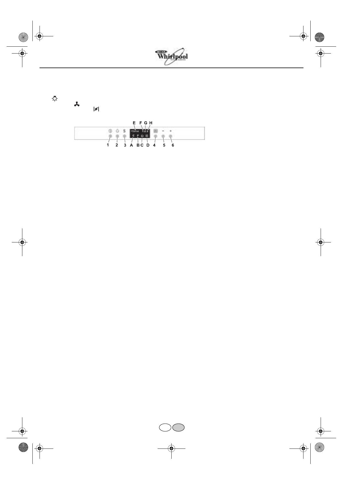
Digital control panel with sensors
The hood is fitted with a series of sensors which enable it to operate in 2 modes:
Automatic
mode
and
Manual mode
.
Automatic mode:
the hood switches on automatically, depending on the ambient temperature (and heat) and variations in this detected by the
hood's sensors. See description of Button 3 function.
Manual mode:
the hood is switched on by the user.
Description of Buttons
1.
OFF/Stand by button:
When the hood is OFF, all the controls are disabled (all LEDs are off).
When on stand-by, the hood is ready to operate in “
Manual mode
”,
LED C
lights up.
2.
Light ON/OFF button: always works, even when the hood is OFF.
3.
ON/OFF button “
Automatic mode
: press to activate this mode (
LED C
and
E
on) the hood switches on automatically, selecting a suitable
extraction speed in accordance with the ambient temperature (and heat) and any variations in this detected by the hood's sensors. Press
again to revert to
“Manual mode”
:
LED E
switches off,
LED C
remains on (stand by). The hood will continue to run for a few minutes
after you have finished cooking but can be turned off by pressing buttons 1 or 3. The automatic function (
LED
on) stops a few minutes
after the motor has been switched off. The automatic function must be switched on every time you start cooking.
4.
ON/OFF button for controlling intensive extraction speed in “
Manual mode
” (
LED D
switches on): when selected, it operates for 5
minutes, after which time the hood automatically reverts to the previously selected extraction speed.
5.
Buttons for controlling extraction speed
1 - 2 - 3
in “
Manual mode
”.
Description of LEDs
A.
Carbon filter
saturation led indicator
: this led lights up to indicate that the carbon filter needs to be cleaned or replaced.
Important: this indicator must be activated in order for the hood to work:
to activate it, press buttons
4
and
5
at the same time -
LED
B
lights up first, followed by
LED A
to indicate that the led indicator is working.
B.
Grease filter saturation led indicator: this led lights up to indicate that the grease filter needs to be cleaned.
C.
“Stand by” led indicator.
D.
Intensive speed led indicator.
E.
“Automatic mode” led indicator.
F.
Extraction speed 1 led indicator.
G.
Extraction speed 2 led indicator.
H.
Extraction speed 3 led indicator.
Reset filters indicator:
After cleaning or replacing the filters, with the hood on Stand by press Button
1
for more than 3 seconds.
Safety function:
this function is activated ONLY with the hood on stand-by, in the event of any SUDDEN, VIOLENT increase in the
temperature detected by the sensors, upon which the hood switches to “
Automatic mode
” and, if necessary, selects a suitable extraction
speed.
Important - upon initial installation:
Selecting the hob type:
to ensure accuratereading by the sensors, the latter must be calibrated to suit the type of hob as follows: with the
hood OFF, press buttons 3 and 4 at the same time until either
LED F
for gas hobs,
LED G
for induction hobs or
LED H
for electric hobs lights
up.
Automatic and manual sensor calibration:
the hood automatically “calibrates” sensor operation, but under certain circumstances (e.g.: in
the event of a prolonged power failure or upon initial installation) calibration can be carried out manually, with the hood OFF, by pressing
buttons
5
and
6
at the same time for more than 3 seconds, otherwise you can wait until the hood carries out calibration automatically.
PRODUCT SHEET
GBTR
31833190GB.fm Page 4 Wednesday, December 21, 2005 3:36 PM
5019 318 33190
Maintenance
ALWAYS disconnect the hood from the mains before performing
maintenance.
Wash the
grease filter
and the
carbon filter
in a dishwasher once a
month, at the highest possible temperature, using normal dishwasher
detergent. It is recommended to wash the filters on the their own.
After washing, reactivate
the carbon filter
by drying it in the oven at
100 °C for 10 minutes. Fit a new carbon filter every 3 years.
Remove the grease filters - Fig. 1:
push the spring release handle
backwards (
f1
) then remove the filter downwards (
f2
).
Clean the perimeter extraction panel (if provided) as often as
the grease filter
, using a cloth and a mild liquid detergent.
Never use abrasive substances.
Clean the sensor plate regularly.
Replacing bulbs
1.
Use a small screwdriver or any other suitable tool to prise off (
m-
Fig. 1
) the lamp cover (
p-Fig.1
).
2.
Remove the burnt-out bulb.
Use max 20 W halogen bulbs only, taking care not to touch them
with your hands.
3.
Close the lighting unit (snap-on).
Fitting the carbon filter:
1.
Remove the grease filter (
f1/f2 - Fig. 1
).
2.
Remove the filter holder by turning the knobs
(
g - Fig. 2
) through.
3.
Fit the carbon filter (
i - Fig. 2
) in the filter holder
(
h - Fig.2
).
Reverse the above procedure to re-fit the filter holder and grease
filter.
Fig. 2
f3
* Only present on some models
Fig. 1
GBTR
31833190GB.fm Page 5 Wednesday, December 21, 2005 3:36 PM
1 / 1

Whirlpool AKR 666 IX Program Chart

Category
Cooker hoods
Type
Program Chart
This manual is also suitable for

Ask a question and I''ll find the answer in the document

Finding information in a document is now easier with AI

Ask the document