PAGE 7
a. Disconnect power.
b. Reverse any two field power leads to the ERS.
c. Reapply power.
7. Disconnect main power to unit before making
adjustment to economizer and/or ERS unit.
8. Remove all jumpers and replace ERS control access
cover.
9. Set thermostat to normal operating position.
10. Restore power to unit.
Figure 22
Figure 21
ECONOMIZER MODE
MAINTENANCE
Motor Maintenance
All motors use prelubricated sealed bearings; no further
lubrication is necessary.
Mechanical Inspection
Make visual inspection of dampers, linkage assemblies
and ERS rotating bearings during routine maintenance.
Filters should be checked periodically and cleaned when
necessary. Filter is located in fresh air hoods. DO NOT
replace permanent filters with throwaway type filters.
Belt Alignment
Proper alignment is essential to maintain long V-Belt life.
Belt alignment should be checked every time belt
maintenance is performed, each time the belt is replaced,
and whenever sheaves are removed or installed.
Belt Installation
Always move the drive unit forward so the belt can be
easily slipped into the groove without forcing them. Never
force the belt into a sheave with a screw driver or wedge.
You will damage the fabric and break the cords. It is
recommended that the pulley center distances be offset by
¾" for proper length. This will allow the motor assembly to
slide forward to remove belt and backward for belt tension.
Belt Tension
Measure the span length (center distance between pulleys
when belt is snug). Mark center of span, then apply a force
(6 to 9 Lbs on new belts) perpendicular to the span large
enough to deflect the belt 164" for every inch in span length.
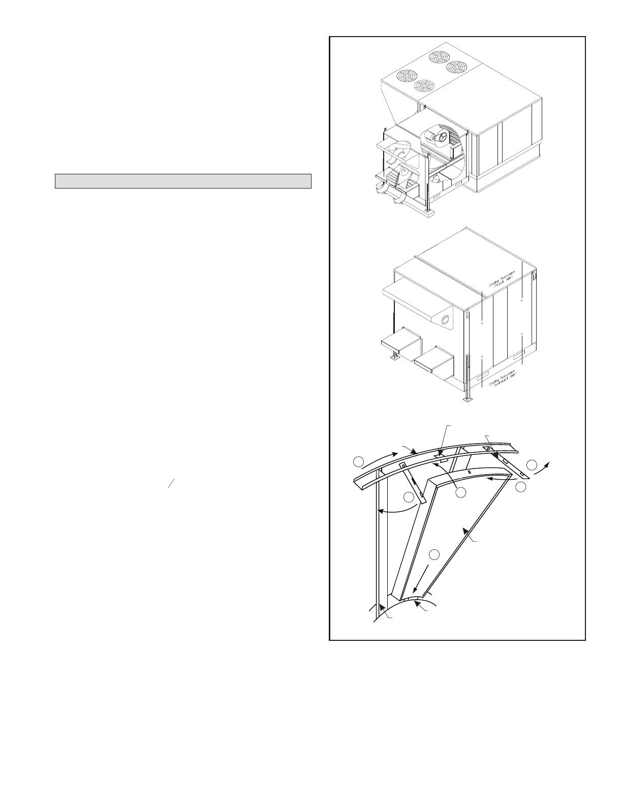
Energy Wheel Maintenance
Eight pie-shaped ERS segments, are seated on stops
between the segment retainer which pivots on the wheel
rim and secured to the hub and rim of wheel. Annual
inspection of the self cleaning wheel is recommended.
With power disconnected, remove ERS access panels
(rear) and unplug [J150 and P150] (Refer to wiring
diagrams in this instruction manual). Remove segment
and wash with water and/or mild detergent.
To install wheel segments follow steps A through E . See
Figure 23. Reverse procedure for segment removal.
A. Unlock two segment retainers (one on each side of the
selected segment opening.
B. With the embedded stiffener facing the motor side,
insert the nose of the segment between the hub plates.
C. Holding segment by the two outer corners, press the
segment towards the center of the wheel and inwards
against the spoke flanges. If hand pressure does not
fully seat the segment, insert the flat tip of a screw
driver between the wheel rim and outer corners of the
segment and apply downward force while guiding the
segment into place.
D. Close and latch each segment retainer under segment
retaining catch.
E. Slowly rotate the wheel 180o. Install the second
segment opposite the first for counterbalance. Rotate
the two installed segment 90o to balance the wheel
while the third segment is installed. Rotate the wheel
180o again to install the fourth segment. Repeat this
sequence with the remaining four segments.
B
C
A
D
E
D
HUB
SEGMENT
FIGURE 23
SPOKE
SEGMENT RETAINER CATCH
WHEEL RIM SEGMENT RETAINER


