Page is loading ...

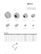
Installation instructions
Roxtec HD 32 with
CM BG™ B modules
Components
Stayplate CM BG B modules Compression unit
C Wedge HD AISI 316
HD 32 frame
including gasket
Counterframe Nuts Fasteners for protective
bonding conductor
Roxtec Lubricant
Safetyinformation
Roxtec recommends that all installations
are performed without facility operation.
Follow national regulations and installation
codes. Any action affecting the routed
service should be performed according to
manufacturer recommendations.
Module size For cable outer diameter
min-max
CM 20 BG B 4-14.5
CM 20w40 BG B 3.5-16.5
CM 30w40 BG B 10-25
CM 40 10-32 BG B 9.5-32.5
CM 40 BG B 21.5-34.5
RoxtecCMBG™Bmodules
Measuresinmillimeters(mm)
Roxtec CM BG™ B solid modules
Module size
CM 10w40/0 BG B
CM 20/0 BG B
CM 40/0 BG B
Note:
The range of the modules indicates the smallest diameter of the exposed cable armor to the largest diameter of the cable
jacket. Modules with core can be used as spare parts.

A B
F
C
C
E
D
D
A B
E
D
A: Environmental side
B: Termination/interior side
C: Removable layers
D: Cable armor
E: Module braid
F: Cable jacket
RoxtecCMBG™Bmodule
Aperture dimensions
Max wall/cabinet thickness: 4 mm
R3 (4x)
216
110 +1.0
-0.5
+1.0
-0.5
10 mm and 13 mm spanner
(not included)
Cable stripper tool.
Recommended by the cable
manufacturer
(not included)
Continuity tester
(not included)
Roxtec
installation tools
(not included)
Tools
Packing space
As module installation example shows, 160 mm can be the result
of 3 pieces of CM 40 10-32 BG B and 2 pieces of CM 20w40 BG B.
Different module configurations must be totally 160 mm.
CM 20w40 BG B 20
CM 20w40 BG B 20
CM 40 10-32 BG B 40
CM 40 10-32 BG B 40
CM 40 10-32 BG B 40
160

Installation
1
Route the protective bonding
conductor through the aperture.
2
Remove all nuts and the two
counter frames.
3
Attach the protective bonding
conductor to the earthing
terminal.
4
Insert the frame from the outside
of the cabinet. Ensure that the
gasket is placed between the
frame and the cabinet.
A
5
Observe the intended wedge
areas (A) without stopping edges.
6
Attach the two counter frames
from the inside of the cabinet.
7
Tighten the nuts crosswise in
small steps. Recommended
torque 4 Nm. Do not overtighten
the nuts.
8
All BG frames must be clean
and have electrical contact
with protective earth. National
regulations apply.
11
Correct placement of a cable in
a CM BG B module. The cable
armor shall be visible outside the
module.
12
Remove the core and fold out the
braid.
9
Remove the outer jacket and any
plastic foil. The cable armor shall
be clean and conductive.
10
Secure the end of the cable
armor. Suggestions for cable
preparations are available on
www.roxtec.com.

22
Insert the modules at an angle
from the backside of the transit
according to your installation
plan.
23
Turn the modules in line with the
frame.
24
Push the modules in place.
Ensure that the module rests
against the stopping edge at the
front.
A
16
Achieve a gap of 0.1-1.0 mm (A)
between the module halves by
peeling off layers. The cable
armor shall be in contact with the
braid.
TM
13
Adapt the layers that are in
contact with the cable jacket.
15
Fold the braid tightly inside the
module half.
18
Lubricate the sealing surfaces
of all modules with Roxtec
Lubricant. Avoid excess lubricant
on the braid.
19
Lubricate the sealing surfaces
of the spare modules. Do not
remove the core.
BG B
BG B
TM
14
Adapt the layers that are in
contact with the cable armor.
A
The number of layers may not
differ (A) by more than one
between the corresponding
module halves.
17 20
Lubricate the sealing surfaces of
the solid modules.
21
Lubricate the inside surfaces of
the frame all around, especially
into the corners. Lubricate the
area that will be in contact with
the braid sparsely.

25
Insert the cables through the
frame.
31
Drop the stayplate on top of
the last module. Make sure the
combinations of modules equal
the 160 mm packing space.
30
Lift up the stayplate and insert
the last module underneath it.
29
Before inserting the final module,
insert a stayplate.
32
Use a Roxtec pre-compression
tool to make space for the
compression units if required.
Insert the compression units until
stop. Do not tighten the first
compression unit until the second
compression unit is inserted.
35
The compression units can be
placed with the screwhead facing
the inside (B) or the outside (A) of
the frame.
A B
36
26
When placing cables in modules,
the cable armor shall be visible
outside the module at the
termination side.
27
Place cables, according to your
packing plan, in the module
halves. Place corresponding
module halves on top.
28
For pass-through cables, cable
armor shall be visible on the
termination side.
Lubricate the sealing surfaces of
the compression units.
34
Turn the screw of the compression
units counter-clockwise to full stop.
33

38
Visible excess lubricant is a sign
of good compression. Make
sure that all modules are placed
correctly and fully inserted after
compression.
39
If applicable, check that the
protective bonding conductor is
correctly installed.
40
Verify earth continuity from each
cable armor to the earthing
terminal using a suitable
instrument.
37
Tighten the screws of the
compression units alternately
until full stop, approx. 20 Nm.

Disassembly and reinstallation
1
Untighten the screws of the
compression units and push
them.
5
Continue to remove the modules
by pulling them out from the
backside of the frame. Do not
damage the braids.
3
Lift up the stayplate and push
out the first module from the
front side.
4
Remove the stayplate.
2
Remove the compression units.
6
The inside surfaces of the
exposed packing space shall be
clean and conductive.
7
Lubricate the inside surfaces,
especially in the corners.
Continue the reinstallation.

Article number: 168129 Document number: ASS2013000401 version C
Roxtec International AB
Box 540, 371 23 Karlskrona, SWEDEN
PHONE +46 455 36 67 00, FAX +46 455 820 12
EMAIL info@roxtec.com, www.roxtec.com
Roxtec ® and Multidiameter ® are registered trademarks of Roxtec in Sweden and/or other countries.
Note
OIntegrated environmental sealing system for bonding and grounding applications. For use with armored cables.
OFor optimum reliability, wait 24 hours or longer after installation before exposing the cables or pipes to strain or pressure.
OCables shall go straight through the frame.
OTo be used with: Roxtec CM BG B components.
OTo simplify installation in frames with more than one opening, fill all openings before tightening the compression units.
OThe final complete bonding/grounding installation has to comply with applicable codes and regulations.
OApprovals or certificates may include amendments or limitations related to this application.
OThe latest version of this and related documents are found at roxtec.com.
Disclaimer
”The Roxtec cable entry sealing system (”the Roxtec system”) is a modular-based
system of sealing products consisting of different components. Each and every
one of the components is necessary for the best performance of the Roxtec
system. The Roxtec system has been certified to resist a number of different
hazards. Any such certification, and the ability of the Roxtec system to resist
such hazards, is dependent on all components that are installed as a part of
the Roxtec system. Thus, the certification is not valid and does not apply unless
all components installed as part of the Roxtec system are manufactured by or
under license from Roxtec (“authorized manufacturer”). Roxtec gives no perfor-
mance guarantee with respect to the Roxtec system, unless (I) all components
installed as part of the Roxtec system are manufactured by an authorized
manufacturer and (II) the purchaser is in compliance with (a), and (b), below.
(a) During storage, the Roxtec system or part thereof, shall be kept indoors in
its original packaging at room temperature.
(b) Installation shall be carried out in accordance with Roxtec installation
instructions in effect from time to time.
The product information provided by Roxtec does not release the purchaser of the
Roxtec system, or part thereof, from the obligation to independently determine
the suitability of the products for the intended process, installation and/or use.
Roxtec gives no guarantee for the Roxtec system or any part thereof and as-
sumes no liability for any loss or damage whatsoever, whether direct, indirect,
consequential, loss of profit or otherwise, occurred or caused by the Roxtec
systems or installations containing components not manufactured by an aut-
horized manufacturer and/or occurred or caused by the use of the Roxtec
system in a manner or for an application other than for which the Roxtec
system was designed or intended.
Roxtec expressly excludes any implied warranties of merchantability and fitness
for a particular purpose and all other express or implied representations and
warranties provided by statute or common law. User determines suitability of
the Roxtec system for intended use and assumes all risk and liability in con-
nection therewith. In no event shall Roxtec be liable for indirect, consequential,
punitive, special, exemplary or incidental damages or losses.”
Module size Total braid cross-section
mm²
Approximately equivalent
AWG
CM 20 BG B 8
CM 20w40 BG B 4* 11
CM 30w40 BG B 13 6
CM 40 10-32 BG B 21 4
CM 40 BG B 21 4
RoxtecCMBG™Bmodules
Braidconductorproperties
* Per cable
/