Peerless FPE47FH-EU-S User manual
- Category
- Flat panel wall mounts
- Type
- User manual
This manual is also suitable for

Installation and Assembly:
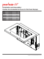
Peerless Environmental Enclosure for Flat Panel Displays
ISSUED: 07-12-10 SHEET #: 061-9056-8 03-05-13
Model # Max Load Capacity Screen Size
FPE47F-S 250 lbs (113 kg) 46"-47"
FPE47FH-S 250 lbs (113 kg) 46"-47"
FPE55F-S 250 lbs (113 kg) 55"
FPE55FH-S 250 lbs (113 kg) 55"
FPE47F-UK-S 250 lbs (113 kg) 46"-47"
FPE47FH-UK-
S
250 lbs (113 kg) 46"-47"
FPE55F-UK-S 250 lbs (113 kg) 55"
FPE55FH-UK-
S
250 lbs (113 kg) 55"
FPE47F-EU-S 250 lbs (113 kg) 46"-47"
FPE47FH-EU-S 250 lbs (113 kg) 46"-47"
FPE55F-EU-S 250 lbs (113 kg) 55"
FPE55FH-EU-S 250 lbs (113 kg) 55"
2300 White Oak Circle • Aurora, Il 60502 • (800) 865-2112 • Fax: (800) 359-6500 • www.peerless-av.com

2 of 50
ISSUED: 07-12-10 SHEET #: 061-9056-8 03-05-13
NOTE: Read entire instruction sheet before you start installation and assembly.
Table of Contents
Parts List ............................................................................................................................................................................... 3
Removing bay door ............................................................................................................................................................5-6
Wall installation .......................................................................................................................................................................7
Depth Adjustment ...................................................................................................................................................................8
Wall plate installation ..............................................................................................................................................................9
Reinstalling door ................................................................................................................................................................. 10
Attaching vertical brackets to display ............................................................................................................................ 11-12
Mounting display.................................................................................................................................................................. 13
Setting Thermostat .............................................................................................................................................................. 14
Filter Replacement .............................................................................................................................................................. 16
Tools Needed for Assembly
• stud fi nder ("edge to edge" stud fi nder is
recommended)
• drill
• Do not begin to install your Peerless product until you have read and understood the instructions and warnings
contained in this Installation Sheet. If you have any questions regarding any of the instructions or warnings, for US
customers please call Peerless customer care at 1-800-865-2112, for all international customers, please contact
your local distributor.
• Due to outdoor environmental conditions such as strong wind gusts, heavy snow, hail, rain, etc. The environmental
enclosure and hardware, must be inspected at least once a year, and immediately following any time winds exceed
90 mph. A qualifi ed installer or inspector must check for signs of rust, loose fasteners, bent metal, etc. If evidence
of excessive wear, deterioration or any unsafe condition is observed, this product must be taken out of service
immediately. Direct all inquiries to customer care if you have any questions.
• Glass face of enclosure must avoid direct sunlight or damage to display may occur.
• This product should only be installed by someone of good mechanical aptitude, has experience with basic building
construction, and fully understands these instructions.
• Make sure that the supporting surface will safely support the combined load of the equipment and all attached
hardware and components.
• Never exceed the Maximum Load Capacity. See page one.
• If mounting to wood wall studs, make sure that mounting screws are anchored into the center of the studs. Use of
an "edge to edge" stud fi nder is highly recommended.
• Always use an assistant or mechanical lifting equipment to safely lift and position equipment.
• Tighten screws fi rmly, but do not overtighten. Overtightening can damage the items, greatly reducing their holding
power.
• This product was designed for use with other outdoor products only.
• This product was designed to be installed on the following wall construction only;
WALL CONSTRUCTION HARDWARE REQUIRED
• Wood Stud Included
• Wood Beam Included
• Solid Concrete Contact Qualifi ed Professional
• Cinder Block Contact Qualifi ed Professional
• Brick Contact Qualifi ed Professional
• Other or unsure? Contact Qualifi ed Professional
WARNING
• phillips screwdriver, 5 mm allen wrench,
fl athead screwdriver
• 5/32" (4 mm) bit for wood stud wall
• level
• hammer

3 of 50
ISSUED: 07-12-10 SHEET #: 061-9056-8 03-05-13
J
C
E
G
H
M
I
F
B
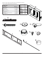
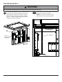
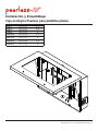
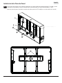
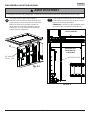
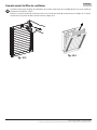
Before you begin, make sure all parts shown are included with your product.
Parts may appear slightly different than illustrated.
L
A
Description Qty. Part #
A enclosure assembly 1 see chart
B adapter brackets 2 201-P1513
C wood screws 6 5S1-015-C03
E
sealed washe
r
6 540-4067
F ROXTEC cable seal 1 600-0107
G
ke
y
1 600-0116
H 12 mm flat head screw 4 520-2325
I
serrated locknu
t
4 530-2021
J wall plate 1 201-P1018
K cord cover plate assembly (not shown) 2 061-7285
L 4 mm allen wrench 1 560-1727
M
1/2" spacer
6 540-1059
Parts List
Model # Part #
FPE47F-S 061-7327
FPE47FH-S
061-7564
FPE55F-S 061-7328
FPE55FH-S
061-7565
FPE47F-UK-S 061-7585
FPE47FH-UK-S
061-7579
FPE55F-UK-S 061-7586
FPE55FH-UK-S
061-7583
FPE47F-EU-S 061-7590
FPE47FH-EU-S
061-7589
FPE55F-EU-S 061-7592
FPE55FH-EU-S
061-7591
Enclosure Assembly (A)
Page is loading ...

5 of 50
ISSUED: 07-12-10 SHEET #: 061-9056-8 03-05-13
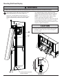
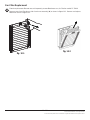
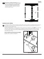
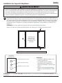
Bay door may be removed for ease of installation
to mounting surface. NOTE: Removal of bay door
is optional. Installation may be completed without
removing bay door.
Insert fl athead screwdriver under brass clip of gas
spring shown in detail 1 and pry up. NOTE: Do not
remove brass clip from gas spring. Pull gas spring
away from bay door.
Optional Removal of Bay Door
1
10-24 x .5"
PHILLIPS SCREWS
A
fi g. 1.1
• Grasp bay door fi rmly. Bay door will swing freely when gas springs are removed.
WARNING
Remove center set of 10-24 x .5" phillips screws
from inside of enclosure assembly (A) as shown in
fi gure 1.1. Slide bay door to the right to disengage
hinges and lift off of enclosure assembly.
1-1
DETAIL 1
GAS SPRING
BRASS CLIP
BRASS CLIP
BAY DOOR
MAIN
ENCLOSURE
ASSEMBLY

6 of 50
ISSUED: 07-12-10 SHEET #: 061-9056-8 03-05-13
Cables may be routed through top, bottom, or rear of main enclosure assembly. An additional available option for
cable entry while maintaining the waterproof seal of the enclosure is the ROXTEC cable gland (F).
Install ROXTEC hardware to top, bottom, or rear of enclosure assembly (A). NOTE: If cables are routed through
rear enclosure assembly hole, wall mount is required for mounting to wall.
Follow the ROXTEC manufacturers' instructions for installation included in ROXTEC cable gland (F) box.
Install cord cover plate assembly (K) to remaining open holes of enclosure assembly (A) as shown in detail 3.
2
Installing Cables
K
A
DETAIL 3
Removal of Rear Supports: Remove 3" serrated
washer head screws and locknuts at top and
bottom of rear supports as shown in detail 2 and
lift rear supports out.
1-2
DETAIL 2
REAR SUPPORT
3" SCREW
LOCKNUT
LOCKNUT
3" SCREW

7 of 50
ISSUED: 07-12-10 SHEET #: 061-9056-8 03-05-13
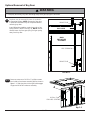
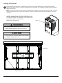
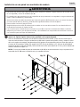
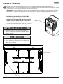
Installation to Wood Stud Wall
NOTE: This step is for mounting enclosure assembly (A) fl ush against supporting surface. For use with
mount, follow instructions provided with wall mount.
Use a stud fi nder to locate the edges of the studs and draw a vertical line down each stud’s center. Place
enclosure assembly (A) on wall as a template, level and mark the center of the six mounting holes. Make sure
that the mounting holes are on the stud centerlines. Drill six 5/32" (4 mm) dia. holes 2.5" (64 mm) deep. Make
sure that the enclosure is level and secure it using six 2.5" wood screws (C) and six washers (E) as shown in
fi gure 3.1.
NOTE: If cord cover plate assembly (K) is used on the rear of the enclosure, you may use the 1/2" spacer (M)
between enclosure assembly and wall surface.
• DO NOT lift more weight than you can handle. Always use an assistant or mechanical lifting equipment to safely lift
and position enclosure assembly (A).
• Installer must verify that the supporting surface will safely support the combined load of the equipment and all
attached hardware and components.
• Tighten wood screws so that the enclosure assembly is fi rmly attached, but do not overtighten. Overtightening can
damage the screws, greatly reducing their holding power.
• Never tighten in excess of 80 in. • lbs. (9 N.M.).
• Make sure that mounting screws are anchored into the center of the stud. The use of an "edge to edge" stud fi nder
is highly recommended.
• Hardware provided is for attachment of mount through standard thickness drywall or plaster into wood studs.
Installers are responsible to provide hardware for other types of mounting situations.
WARNING
3
fi g. 3.1
C
E
A

8 of 50
ISSUED: 07-12-10 SHEET #: 061-9056-8 03-05-13
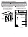
NOTE: The installed display should allow a 1/2" air gap between the front of the display and the interior surface of
the window. A display mounted directly against the window will create a dead air space that traps heat which may
affect the funtionality of both the display and the enclosure mount.
Measure the depth of your display. Choose the appropriate fi xed stop-position from the chart below. Reinstall rear
supports with 3" serrated washer head screws and locknuts into appropriate fi xed stop-position as shown in fi gure
4.1. NOTE: Be sure "UP" arrow of rear support is pointing up as shown in fi gure 4.2.
Do not tighten fasteners.
• Failure to allow this space for air circulation and to allow heat to dissipate from the display may effect the visual ap-
pearance and/or cause damage to your display.
WARNING
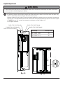
Depth Adjustment
FIXED STOP-POSITION #1
FIXED STOP-POSITION #2
FIXED STOP-POSITION #3 FIXED STOP-POSITION #4
FIXED STOP-POSITION #5
4
Depth of Display
Fixed Stop-Position
1-1/8" - 2-1/8" (29 - 54 mm) #1
1-3/4" - 2-3/4" (44 - 70 mm) #2
2-3/8" - 3-3/8" (60 - 86 mm) #3
3" - 4" (76 - 102 mm) #4
3-5/8" - 4-5/8" (92 - 117 mm) #5
fi g. 4.1
fi g. 4.2
REAR SUPPORT
LOCKNUT
3" SCREW

9 of 50
ISSUED: 07-12-10 SHEET #: 061-9056-8 03-05-13
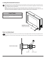
Wall Plate Installation
Attach wall plate (J) to rear supports with four 12 mm fl at head screws (H) and four serrated locknuts (I). Slide
wall plate (J) to desired position (+/- 3/4") vertically.
Level wall plate and tighten 12 mm fl at head screws (H) using 4 mm allen wrench (L).
H
H
J
I
REAR SUPPORT
4-1

10 of 50
ISSUED: 07-12-10 SHEET #: 061-9056-8 03-05-13
Reinstalling Bay Door
If bay door was removed in step 1, lower bay door
onto enclosure assembly and slide to the left to
engage hinges. Align holes of center hinge with
holes of enclosure assembly (A). Reinstall two
10-24 x .5" phillips screws to inside of enclosure
assembly as shown in fi gure 5.1.
5
fi g. 5.1
10-24 x .5"
PHILLIPS
SCREWS
A
• Grasp bay door fi rmly. Bay door will swing freely when gas springs are removed.
WARNING
Secure both gas springs to sides of bay door by
pressing on as shown in detail 4.
NOTE: Be sure thin end of gas spring is
attached to main enclosure assembly.
DETAIL 4
GAS SPRING
BAY DOOR
MAIN ENCLOSURE
ASSEMBLY
5-1

11 of 50
ISSUED: 07-12-10 SHEET #: 061-9056-8 03-05-13
Installing Adapter Brackets
To prevent scratching the display, set a cloth on a fl at, level surface that will support the weight of the display.
Place display face side down. If display has knobs on the back, remove them to allow the adapter brackets to be
attached. Place adapter brackets (B) on back of display, align to holes, and center on back of display as shown
below. Attach the adapter brackets to the back of the display using the appropriate combination of screws, multi-
washers and spacers as shown in steps 6-1 and 6-2.
NOTE: Top and bottom holes must always be used.
Verify that all holes are properly aligned, and then tighten screws using a phillips screwdriver.
6
NOTE: "X" dimensions should be equal.
B
CENTER BRACKETS VERTICALLY
ON BACK OF DISPLAY
X
X
MULTI-WASHER
MEDIUM HOLE FOR M5 SCREWS
SMALL HOLE FOR M4 SCREWS
LARGE HOLE FOR M6 SCREWS
Notes:
• The number of fasteners used will vary, depending
upon the type of display.
• Multi-washers and spacers may not be used,
depending upon the type of display.
• Use the corresponding hole in the multi-washer
that matches your screw size as shown.
• Tighten screws so adapter brackets are fi rmly attached. Do not tighten with excessive force. Overtightening can cause
stress damage to screws, greatly reducing their holding power and possibly causing screw heads to become de-
tached. Tighten to 40 in. • lb (4.5 N.M.) maximum torque.
• If screws don't get three complete turns in the display inserts or if screws bottom out and bracket is still not tightly
secured, damage may occur to display or product may fail.
WARNING

12 of 50
ISSUED: 07-12-10 SHEET #: 061-9056-8 03-05-13
Begin with the shortest length screw, hand thread through multi-washer and adapter bracket into display as
shown below. Screw must make at least three full turns into the mounting hole and fi t snug into place. Do not
over tighten. If screw cannot make three full turns into the display, select a longer length screw from the baffl ed
fastener pack. Repeat for remaining mounting holes, level brackets and tighten screws.
NOTE: Spacers may not be used, depending upon the type of display.
Begin with longer length screw, hand thread through multi-washer, adapter bracket and spacer in that order into
display as shown below. Screw must make at least three full turns into the mounting hole and fi t snug into place.
Do not over tighten. If screw cannot make three full turns into the display, select a longer length screw from the
baffl ed fastener pack. Repeat for remaining mounting holes, level brackets and tighten screws.
For Flat Back Display
For Bump-out or Recessed Back Display
6-2
6-1
If you have any questions, please call Peerless customer care at 1-800-865-2112.
If you have any questions, please call Peerless customer care at 1-800-865-2112.
SCREW
MULTI-WASHER
ADAPTER BRACKET (B)
Display
SCREW
MULTI-WASHER
ADAPTER BRACKET (B)
Display
SPACER

13 of 50
ISSUED: 07-12-10 SHEET #: 061-9056-8 03-05-13
Hook adapter brackets (B) onto wall plate (J) then
slowly swing display in as shown in fi gure 7.1.
Remove 3" serrated washer head screws from
bottom of rear supports. Swing rear supports up to
access safety/security screws as shown in fi gure
7.2.
7
• Always use an assistant or mechanical lifting equipment to safely lift and position the fl at panel displays.
WARNING
DETAIL 5
fi g. 7.1
B
J
J
B
Turn safety/security screws, using 4 mm allen
wrench (L), clockwise at least six times to prevent
display from being removed as shown in detail 5.
NOTE: To lock the display down, tighten safety
screws to wall plate as shown in detail 5.
Route cables through ROXTEC cable seal and plug
into appropriate connection. Reinstall 3" serrated
washer head screws and locknuts to bottom of rear
supports. Tighten all fasteners.
fi g. 7.2
Mounting Flat Panel Display
3" SERRATED WASHER
HEAD SCREWS
• Do not postion AV and power cables close to heater
or damge to cables may occur. See next page for
more information.
CAUTION

14 of 50
ISSUED: 07-12-10 SHEET #: 061-9056-8 03-05-13
Refer to display manufacturers' requirements for optimal environment temperature. If display manufacturer's
requirments state that cooler or warmer temperatures are acceptable, use a fl atblade screwdriver to adjust dial to
desired temperature.
NOTE: Thermostat inside enclosure assembly will determine at what time the Exhaust Fan will initiate. The Intake
Fan will operate at all times. For all other questions, refer to thermostat instruction sheet included in enclosure
assembly.
HEATER INFORMATION (FPE47FH-S,FPE55FH-S only)
Thermostat of heater is not adjustable. The heater will turn
on at 40°±7° and will turn off at 60°±5°.
Heater uses a 20 amp fuse.
Setting Thermostat
8
DIAL
HEATER
THERMOSTAT
• Frame of heater will be hot when turned on. Turn
heater off allowing frame to cool prior to service.
WARNING
• Do not postion AV and power cables close to heater
or damge to cables may occur.
CAUTION

15 of 50
ISSUED: 07-12-10 SHEET #: 061-9056-8 03-05-13
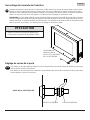
Locking Environmental Enclosure
Gently lower bay door. Using key (G) rotate door locks clockwise until key cannot turn. Make sure that the key has
fully rotated to seal enclosure. If key does not fully rotate, door lock may need to be adjusted for a looser seal. See
step 9-1 below for door lock adjustment.
NOTE: Gasket seal of bay door must be fully compressed to allow for a water tight seal. Test seal of door by
inserting a sheet of paper in between the door seal and the enclsosure seal. If the sheet of paper is easily removed,
door lock may need to be adjusted for a tighter seal. See step 9-1 below for door lock adjustment.
9
G
To allow for a tighter seal, loosen top nut of door locks 1/4" then tighten bottom nut of door locks against lock tab.
To allow for a more loose seal, loosen bottom nut of door locks 1/4" then tighten top nut of door locks against lock
tab.
Door Lock Adjustment
9-1
FRONT OF BAY DOOR
TOP NUT BOTTOM NUT
NUMBER OF LOCKS
ON DOOR MAY VARY
FROM ILLUSTRATION
• Be careful not to pinch your fi ngers when opening and
closing bay door.
CAUTION

16 of 50
ISSUED: 07-12-10 SHEET #: 061-9056-8 03-05-13
Filterfan replacement fi ltermats are sold separately at www.fi lterfanusa.com, for Filterfan model PF 22000.
Remove cover from Filterfan on side of enclosure assembly (A) as shown in fi gure 10.1. Remove and replace
fi ltermat as shown in fi gure 10.2.
Fan Filter Replacment
P
U
L
L
10
fi g. 10.1
fi g. 10.2
© 2013, Peerless Industries, Inc. All rights reserved.
All other brand and product names are trademarks or registered trademarks of their respective owners.
Page is loading ...
Page is loading ...
Page is loading ...
Page is loading ...
Page is loading ...
Page is loading ...
Page is loading ...
Page is loading ...
Page is loading ...
Page is loading ...
Page is loading ...
Page is loading ...
Page is loading ...
Page is loading ...
Page is loading ...
Page is loading ...

Installation et montage :
Enceinte de Protection Peerless pour Écrans Plats
PUBLIÉ LE: 07-12-10 FEUILLE n
o
: 061-9056-8 03-05-13
2300 White Oak Circle • Aurora, Il 60502 • (800) 865-2112 • Fax: (800) 359-6500 • www.peerless-av.com
Modèles nº Capacité de charge maximale Taille de l'écran
FPE47F-S 250 lbs (113 kg) 46 - 47 po
FPE47FH-S 250 lbs (113 kg) 46 - 47 po
FPE55F-S 250 lbs (113 kg) 55 po
FPE55FH-S 250 lbs (113 kg) 55 po
FPE47F-UK-S 250 lbs (113 kg) 46 - 47 po
FPE47FH-UK-
S
250 lbs (113 kg) 46 - 47 po
FPE55F-UK-S 250 lbs (113 kg) 55 po
FPE55FH-UK-
S
250 lbs (113 kg) 55 po
FPE47F-EU-S 250 lbs (113 kg) 46 - 47 po
FPE47FH-EU-S 250 lbs (113 kg) 46 - 47 po
FPE55F-EU-S 250 lbs (113 kg) 55 po
FPE55FH-EU-S 250 lbs (113 kg) 55 po
Page is loading ...
Page is loading ...
Page is loading ...
Page is loading ...
Page is loading ...
Page is loading ...
Page is loading ...
Page is loading ...
Page is loading ...
Page is loading ...
Page is loading ...
Page is loading ...
Page is loading ...
Page is loading ...
Page is loading ...

49 of 50
ISSUED: 07-12-10 SHEET #: 061-9056-8 03-05-13
© 2013 Peerless Industries, Inc.
Peerless Industries, Inc. (“Peerless”) warrants to original end-users of Peerless® products will be free from defects in material and workmanship, under normal
use, for a period of fi ve years from the date of purchase by the original end-user (but in no case longer than six years after the date of the product’s manufacture).
At its option, Peerless will repair or replace, or refund the purchase price of, any product which fails to conform with this warranty.
In no event shall the duration of any implied warranty of merchantability or fi tness for a particular purpose be longer than the period of the applicable
express warranty set forth above. Some states do not allow limitations on how long an implied warranty lasts, so the above limitation may not apply to you.
This warranty does not cover damage caused by (a) service or repairs by the customer or a person who is not authorized for such service or repairs by Peerless,
(b) the failure to utilize proper packing when returning the product, (c) incorrect installation or the failure to follow Peerless’ instructions or warnings when installing,
using or storing the product, or (d) misuse or accident, in transit or otherwise, including in cases of third party actions and force majeure.
In no event shall Peerless be liable for incidental or consequential damages or damages arising from the theft of any product, whether or not secured
by a security device which may be included with the Peerless® product. Some states do not allow the exclusion or limitation of incidental or consequential
damages, so the above limitation or exclusion may not apply to you.
This warranty is in lieu of all other warranties, expressed or implied, and is the sole remedy with respect to product defects. No dealer, distributor, installer or other
person is authorized to modify or extend this Limited Warranty or impose any obligation on Peerless in connection with the sale of any Peerless® product.
This warranty gives specifi c legal rights, and you may also have other rights which vary from state to state.
*This warranty does not cover corrosion or rust trails resulting from damaged paint or surface chipping which exposes raw metal to the elements. Surface
corrosion from scratches, nicks and chips is not covered. Peerless Industries, Inc. establishes a warranty period of corrosion for one year for product
manufactured or supplied by Peerless.
LIMITED FIVE-YEAR WARRANTY*
www.peerless-av.com
© 2013 Peerless Industries, Inc.
Peerless Industries, Inc. (Peerless) les garantiza a los usuarios fi nales originales de los productos Peerless® que los productos Peerless® estarán libres de
defectos de materiales o de manufactura, en condiciones de uso normal, durante un periodo de cinco (5) años a partir de la fecha en la que el usuario fi nal
original compre cualquier producto (pero, en ningún caso, durante un periodo mayor de 6 años después de la fecha de manufactura del producto). Queda a la
discreción de Peerless, reparar, reemplazar o rembolsar el precio de compra de cualquier producto que no cumpla esta garantía.
La duración de toda garantía implícita de comerciabilidad o de idoneidad para un propósito en particular no sobrepasará en caso alguno el periodo
de vigencia de la garantía explícita correspondiente indica en lo anterior. Algunos Estados no permiten que se establezcan limitaciones en relación con el
periodo de duración de una garantía implícita, de manera que es posible que la limitación expuesta en lo anterior no sea pertinente a usted.
Esta garantía no cubre daños causados por (a) trabajos de mantenimiento o de reparación hechos por el cliente o alguna persona que no esté autorizada por
Peerless para realizar dichos trabajos de mantenimiento o de reparación, (b) no empacar el producto como es debido si lo devuelve, (c) hacer una instalación
incorrecta o no seguir las instrucciones o las advertencias de Peerless al instalar, utilizar o guardar el producto o (d) el mal uso o los accidentes, en tránsito o en
otras circunstancias, incluidos los casos relacionados con las acciones de terceros o una fuerza mayor.
Peerless no tendrá responsabilidad en ningún caso de daños y perjuicios incidentales o indirectos o de daños y perjuicios que surjan por el robo de
cualquier producto, ya sea que el mismo esté o no esté asegurado con un dispositivo de seguridad que se haya incluido con el producto de Peerless®.
Algunos Estados no permiten que se excluyan o se establezcan limitaciones en relación con los daños y perjuicios incidentales o indirectos, de manera que es
posible que la limitación o la exclusión expuesta en lo anterior no sea pertinente a usted.
Esta garantía remplaza toda otra garantía, expresa o implícita, y es el único recurso en lo que respecta a los defectos del producto. Ningún concesionario,
distribuidor, instalador ni ninguna otra persona está autorizada a modifi car o extender esta Garantía Limitada ni a imponer obligación alguna a Peerless en
relación con la venta de cualquier producto de Peerless®.
Esta garantía concede derechos específi cos creados por ley y es posible que usted, además, tenga otros derechos que varían de acuerdo con el Estado donde
se encuentre.
*Esta garantía no cubre la corrosión ni las manchas de oxidación que sean el resultado de pintura arruinada o superfi cies rayadas, que expongan el metal no
tratado a los elementos. No se cubre la corrosión de la superfi cie a causa de rayones, muescas o descascarillados. Peerless Industries, Inc. establece un
periodo de garantía de un (1) año por corrosión para los productos manufacturados o suministrados por Peerless.
GARANTIE DE CINQ ANS*
www.peerless-av.com
Page is loading ...
-
 1
1
-
 2
2
-
 3
3
-
 4
4
-
 5
5
-
 6
6
-
 7
7
-
 8
8
-
 9
9
-
 10
10
-
 11
11
-
 12
12
-
 13
13
-
 14
14
-
 15
15
-
 16
16
-
 17
17
-
 18
18
-
 19
19
-
 20
20
-
 21
21
-
 22
22
-
 23
23
-
 24
24
-
 25
25
-
 26
26
-
 27
27
-
 28
28
-
 29
29
-
 30
30
-
 31
31
-
 32
32
-
 33
33
-
 34
34
-
 35
35
-
 36
36
-
 37
37
-
 38
38
-
 39
39
-
 40
40
-
 41
41
-
 42
42
-
 43
43
-
 44
44
-
 45
45
-
 46
46
-
 47
47
-
 48
48
-
 49
49
-
 50
50


Peerless FPE47FH-EU-S User manual
- Category
- Flat panel wall mounts
- Type
- User manual
- This manual is also suitable for
Ask a question and I''ll find the answer in the document
Finding information in a document is now easier with AI
in other languages
- français: Peerless FPE47FH-EU-S Manuel utilisateur
- español: Peerless FPE47FH-EU-S Manual de usuario
Related papers
-
Peerless PLP-V6X5 Installation guide
-
-
-
-
-
Peerless ACC962 Owner's manual
-
-
-
-
Other documents
-
Peerless Industries LCFL RCA27 User manual
-
-
Xtreme 18012 Installation guide
-
-
RCA MAF15BKR User manual
-
 Roxtec CM BG B Series Installation Instructions Manual
-
 Roxtec RS 25 OMD Installation guide
-
-
-
 ClosetMaid 1398 Operating instructions


