Page is loading ...

- 1 -
Rivet-Span.
Installation Instructions
32-50500-000A
SEPTEMBER 1996
BORROUGHS CORPORATION
3002 N. BURDICK STREET • KALAMAZOO, MI 49004-3483
800-748-0227 • FAX 616-342-4161 • CANADA 800-968-0162
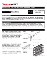
Bulk Storage Unit
Angle Post
Support Tie
Shelving Unit
Double
Rivet
Angle
Beams
Single Rivet
Beam
Angle
Post
5/8" Thick
Particle Board
Decking
Double Rivet
Angle Beams
Foot Plate
Angle Post
Single Rivet
Beams
Double
Rivet
Angle
Beams
Double Rivet
Angle Beams
Angle Post
Double Rivet
Angle Beam
or
Double Rivet
Channel Beam
5/8" Thick
Particle
Board
Decking
IMPORTANT - PRODUCT LIABILITY INFORMATION
READ ALL INSTRUCTIONS BEFORE PROCEEDING WITH ASSEMBLY. VITAL PRODUCT INFORMATION PERTAINING TO
PROPER SETUP AND CAUTIONS ARE INCLUDED. FAILURE TO FOLLOW THESE INSTRUCTIONS MAY RESULT IN
PERSONAL INJURY AND/OR PROPERTY DAMAGE.
RETAIN THIS MANUAL FOR FUTURE REFERENCE
SR= Single Rivet Beams
LP = Double Rivet Low Profile Beams
DR =Double Rivet Angle Beams
ZB= Double Rivet Z Beams
DH =Double Rivet Angle Beams with Support Tie
CH =Double Rivet Channel Beams with Support Tie
PR= Punched Double Rivet Angle Beams
(to accept record storage support angles)
PH= Punched Double Rivet Channel Beams with Support Tie
(to accept record storage support angles)
Pre-configured Catalog Units
B 7 2 2 4 D R 4 7
Starter or Adder Unit
Depth of Unit in Inches
Width of Unit in Inches
B = Starter; A = Adder
Type of Beam
Number of Beam Levels
Height of Unit in Feet
®
Part Numbering System
Support Tie

- 2 -
General Instructions:
1. Check parts and bundles against packing slip to be sure all parts and bundles were received.
2. Sort parts so that like parts are together. This will make installation easier and faster.
3. Read through the entire instructions carefully - before attempting to assemble the units.
Tools Required:
1. Rubber mallet or a hammer and block of wood.
2. Two pairs of pliers or two 7/16" wrenches for installing Foot Plates and/or Support Ties.
Beam Profiles
Single Rivet Beam
Shelving - standard duty
Double Rivet Low Profile Beam
Shelving - heavy duty
Double Rivet Z Beam
Shelving - heavy duty
Bulk Storage - standard duty
Double Rivet Angle Beam
Bulk Storage - standard duty
Double Rivet Channel Beam
Bulk Storage - heavy duty
Tire Beam
Tires and Wheels - standard duty
12" to 60"
69" & 72"
Z Tie
Support Tie
Tire Beam
Wall Tie
Aisle Tie
Double Rivet Angle Beam
Back Spacer Tie
Particle Board
Tie Plate Angle Post
Heavy Duty Angle Post
Angle Post
Single Rivet Beam
Double Rivet Low Profile Beam
Double Rivet Z Beam
Double Rivet Channel Beam
T Post
Foot Plate
At no time should personnel be allowed to climb or stand on shelving product. Safe access to all shelving levels should be provided with ladders
and/or other devises which are in accordance with applicable OSHA regulations.
Wall, floor or top tie anchoring is recommended for units when the height to depth ratio exceeds 4.
Example: A 7' high x 18" deep unit has a height to depth ratio of 4.67 and should be attached to a firm restraint, such as a floor, wall or tied
overhead across the aisle to an opposite upright assembly.
Important Notice
Intermix beam families on the same beam level
These beam families can be intermixed without
decking problems:
✦ Single Rivet Beams
✦ Double Rivet Low Profile Beams
✦ Double Rivet Z Beams
These beam families can be intermixed without
decking problems:
✦ Double Rivet Angle Beams
✦ Double Rivet Channel Beams
The above groupings cannot be intermixed and
support decking.

- 3 -
Bulk Storage Unit / Shelving Unit:
Beams are installed by placing both of the rivets in post slots, making sure the rivets are engaged, then striking the beam with a rubber mallet (or by
placing a block of wood over the beam, to protect the finish, and striking with a hammer). See Figure 1. Make sure both rivets are fully seated on the
bottom of the post.
Units require, for stability, a full "perimeter" of double rivet beams, meaning (2) side-to-side and (2) front-to-back, at both top and bottom of each unit.
For best results, assemble the unit in this order:
Assemble the ends of the units installing double rivet beams front-to-back to the top and bottom of the posts. See Figure 2.
NOTE: Pre-configured catalog units - starter unit has (4) angle posts; adder unit has (2) T posts.
Then, attach the double rivet beams right-to-left to the assembled ends, starting on the bottom. When this step is complete, the unit stands on its own.
See Figure 3.
NOTE: Pre-configured catalog channel beam units use angle beams located directly at floor level. Channel beams cannot be located directly at the floor
level due to their larger face; they must be positioned up one hole on the post to allow proper seating of their rivets.
Under Single Unit Under Adjoining Units
Foot Plate - Optional
Fully Seated Rivets
FIGURE 3
FIGURE 1
Back
Double Rivet
Beams
FIGURE 2

- 4 -
Bulk Storage Unit:
Support Ties - Optional
Support ties are used with the bottom and top level left-to-right double rivet angle and channel beams. They
are installed from front-to-back as shown in Figure 4. Beams under 96" use (1) support tie in the middle of the
beam while 96" beams use (2) support ties dividing the beam into thirds.
Intermediate Beam Levels
All units must have double rivet beams, left-to-right and front-to-back, installed at every level. If optional
support ties are required, add to each intermediate level as shown in Figure 4.
Single
Rivet
Beams
Double Rivet
Angle Beam
Single
Rivet
Beams
Single
Rivet
Beam
FIGURE 4
FIGURE 5
FIGURE 6
FIGURE 7
Shelving Unit:
Intermediate Beam Levels
Units 24" or less in depth do not require single rivet beams at every front-to-back
intermediate level.
Units 6', 7' and 8' tall must have (1) level of single rivet beams from the
front to the back located in the middle of the unit. See Figure 5.
Units 9' and 10' tall must have (2) levels of single rivet beams from the
front to the back dividing the unit into thirds. See Figure 6.
Units 11' to 16' tall must have (1) level of double rivet angle beams all the
way around the perimeter, right-to-left and front-to-back located in about
the middle of the unit and front-to-back single rivet angle beams running
from front-to-back located about the midway of the halves. See Figure 7.
Units 30" deep or deeper must have single rivet beams front-to-back at every
intermediate level. Additionally, units 11' to 16' must have an intermediate double
rivet beam level around the perimeter located in the middle of the unit. See
Figure 7.
Accessories:
Tie Plates
Tie plates are recommended to tie adjacent units together and insure structure
stability. Tie plates should be installed as shown in Figure 8 and placed at the
top and bottom of adjacent posts with additional tie plates no more than 48"
apart.
Aisle Ties
Aisle ties are designed to join shelving together and to provide additional
stability over aisle space. See Figure 9. They Are NOT Designed To Carry
Weight or Support Upper Level Walkways. Install on aisle side of post, at
height desired, in the same manner as a beam (See Figure 1). Aisle ties will not
install at the same level as beams.
Back Spacer Ties
Back spacer ties are designed to space shelving when they are used in a back-
to-back configuration and a space is desired between them. See Figure 9. Back
spacer ties are designed and installed the same as the aisle tie. They Are NOT
Designed to Carry Weight.
Wall Ties
Wall ties are designed to tie the shelving to the wall and to provide additional
stability when required. See Figure 9. They Are NOT Designed To Carry
Weight. Install to wall side of post, at height desired and bolt to wall (bolts or
screws not supplied). Wall ties will not install at the same level as beams.
FIGURE 8
Foot Plate
Back Spacer Tie
Aisle Tie
Wall Tie
Wall Tie Floor
Back Spacer Tie
FIGURE 9
Accessories in Use
End View
/