Page is loading ...

WARNING:
• This fixture is intended for installation in accordance with the
National Electric Code (NEC) and all local code specifications.
• Supply wires are not intended for use through or concealed
behind walls, floors, or ceilings.
DIMMING: This LED fixture is compatible with electronic low
voltage dimmers only.
CAUTION – RISK OF SHOCK –
Disconnect Power at the main circuit breaker panel or main fuse
box before starting and during the installation.
1) Assemble mounting screws to backpan using hexnut.
2) At the center of the backpan are knockout slots. Remove
the set that matches your outlet box.
3) Position the backplate over the outlet box. Secure the
backpan to the outlet box using mounting strap screws
provided (these are the shorter of the two screws)
4) Mark the location of the outer keyhole slots of the backplate
to the wall. Be sure to mark only the narrow part of the
keyhole slot. Remove the backplate from the wall. Drill the
holes using an appropriately sized drill bit. Insert the pro
vided anchors into the holes.
5) Grounding instructions: (See Illus. A or B).
A) On fixtures where mounting strap is provided with a
hole and two raised dimples. Wrap ground wire from
outlet box around green ground screw, and thread into
hole.
B) On fixtures where a cupped washer is provided. Attach
ground wire from outlet box under cupped washer and
green ground screw, and thread into mounting strap.
If fixture is provided with ground wire. Connect fixture
ground wire to outlet box ground wire with wire connector
(not provided.) after following the above steps. Never connect
ground wire to black or white power supply wires.
6) Make wire connections (connectors not provided). Reference
chart below for correct connections and wire accordingly.
7) Carefully push wire connections back into outlet box making
sure all connections remain secure.
8) Secure the backpan to the outlet box with the mounting
strap screws.
9) Anchor the backpan to the wall using the set of holes at
each end of fixture using the provided wood screws and
plastic anchors.
10) Slip the holes of the faceplate over mounting screws and
backpan.
11) Secure faceplate to backpan using lockwashers and lock-up
knobs.
12) Carefully lower each diffuser and rest onto the bottom tabs
of the side brackets.
Connect Black or
Red Supply Wire to:
Connect
White Supply Wire to:
Black White
*Parallel cord (round & smooth) *Parallel cord (square & ridged)
Clear, Brown, Gold or Black
without tracer
Clear, Brown, Gold or Black
with tracer
Insulated wire (other than green)
with copper conductor
Insulated wire (other than green)
with silver conductor
*Note: When parallel wires (SPT I & SPT II)
are used. The neutral wire is square shaped
or ridged and the other wire will be round in
shape or smooth (see illus.)
Neutral Wire
Date Issued: 12/14/16 IS-10798LED-US
GREEN GROUND
SCREW
CUPPED
WASHER
OUTLET BOX
GROUND
FIXTURE
GROUND
DIMPLES
WIRE CONNECTOR
OUTLET BOX
GROUND
GREEN GROUND
SCREW
FIXTURE
GROUND
A
B
We’re here to help 866-558-5706
Hrs: M-F 9am to 5pm EST
SEE OTHER SIDE FOR SPANISH TRANSLATIONS.
VEA EL OTRO LADO DE TRADUCCIONES AL ESPAÑOL.
This device complies with part 15 of the FCC Rules. Operation is
subject to the following two conditions: (1) This device may not
cause harmful interference, and (2) this device must accept any
interference received, including interference that may cause un-
desired operation.
Note: This equipment has been tested and found to comply with
the limits for a Class B digital device, pursuant to part 15 of the
FCC Rules. These limits are designed to provide reasonable pro-
tection against harmful interference in a residential installation.
This equipment generates, uses and can radiate radio frequency
energy and, if not installed and used in accordance with the in-
structions, may cause harmful interference to radio communica-
tions. However, there is no guarantee that interference will not
occur in a particular installation. If this equipment does cause
harmful interference to radio or television reception, which can
be determined by turning the equipment off and on, the user is
encouraged to try to correct the interference by one or more of
the following measures:
• Reorient or relocate the receiving antenna.
• Increase the separation between the equipment and receiver.
• Connect the equipment into an outlet on a circuit different from
that to which the receiver is connected.
• Consult the dealer or an experienced radio/TV technician for
help.
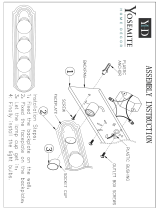
DIFFUSER
LED MODULE
OUTLET BOX
WIRE
CONNECTORS
MOUNTING PLATE
MOUNTING SCREW(S)
HEXNUT(S)
10798LED (USE FOR 10799LED & 10800LED)
FACE PLATE

WARNING:
• This fixture is intended for installation in accordance with the
National Electric Code (NEC) and all local code specifications.
• Supply wires are not intended for use through or concealed
behind walls, floors, or ceilings.
DIMMING: This LED fixture is compatible with electronic low
voltage dimmers only.
CAUTION – RISK OF SHOCK –
Disconnect Power at the main circuit breaker panel or main fuse
box before starting and during the installation.
1) Assemble mounting screws to backpan using hexnut.
2) At the center of the backpan are knockout slots. Remove
the set that matches your outlet box.
3) Position the backplate over the outlet box. Secure the
backpan to the outlet box using mounting strap screws
provided (these are the shorter of the two screws)
4) Mark the location of the outer keyhole slots of the backplate
to the wall. Be sure to mark only the narrow part of the
keyhole slot. Remove the backplate from the wall. Drill the
holes using an appropriately sized drill bit. Insert the
provided anchors into the holes.
5) Connect fixture ground wire to outlet box ground wire with
wire connector. Never connect ground wire to black or white
power supply wire.
6) Make wire connections (connectors not provided). Reference
chart below for correct connections and wire accordingly.
7) Carefully push wire connections back into outlet box making
sure all connections remain secure.
8) Secure the backpan to the outlet box with the mounting
strap screws.
9) Anchor the backpan to the wall using the set of holes at
each end of fixture using the provided wood screws and
plastic anchors.
10) Slip the holes of the faceplate over mounting screws and
backpan.
11) Secure faceplate to backpan using lockwashers and lock-up
knobs.
12) Carefully lower each diffuser and rest onto the bottom tabs
of the side brackets.
Connect Black or
Red Supply Wire to:
Connect
White Supply Wire to:
Black White
*Parallel cord (round & smooth) *Parallel cord (square & ridged)
Clear, Brown, Gold or Black
without tracer
Clear, Brown, Gold or Black
with tracer
Insulated wire (other than green)
with copper conductor
Insulated wire (other than green)
with silver conductor
*Note: When parallel wires (SPT I & SPT II)
are used. The neutral wire is square shaped
or ridged and the other wire will be round in
shape or smooth (see illus.)
Neutral Wire
Date Issued: 12/14/16 IS-10798LED-CB
INSTRUCTIONS
For Assembling and Installing Fixtures in Canada
Pour L’assemblage et L’installation Au Canada
We’re here to help 866-558-5706
Hrs: M-F 9am to 5pm EST
SEE OTHER SIDE FOR CANADIAN FRENCH TRANS-
LATIONS.
VOIR L’AUTRE CÔTÉ POUR LES CANADIENS TRA-
DUCTIONS EN FRANÇAIS.
This device complies with part 15 of the FCC Rules. Operation is
subject to the following two conditions: (1) This device may not
cause harmful interference, and (2) this device must accept any
interference received, including interference that may cause un-
desired operation.
Note: This equipment has been tested and found to comply with
the limits for a Class B digital device, pursuant to part 15 of the
FCC Rules. These limits are designed to provide reasonable pro-
tection against harmful interference in a residential installation.
This equipment generates, uses and can radiate radio frequency
energy and, if not installed and used in accordance with the in-
structions, may cause harmful interference to radio communica-
tions. However, there is no guarantee that interference will not
occur in a particular installation. If this equipment does cause
harmful interference to radio or television reception, which can
be determined by turning the equipment off and on, the user is
encouraged to try to correct the interference by one or more of
the following measures:
• Reorient or relocate the receiving antenna.
• Increase the separation between the equipment and receiver.
• Connect the equipment into an outlet on a circuit different from
that to which the receiver is connected.
• Consult the dealer or an experienced radio/TV technician for
help.
DIFFUSER
LED MODULE
OUTLET BOX
WIRE
CONNECTORS
MOUNTING PLATE
MOUNTING SCREW(S)
HEXNUT(S)
10798LED (USE FOR 10799LED & 10800LED)
FACE PLATE
/


![hykolityHykolity 16 Inch Flush mount LED Ceiling Light Fixture, 25W [200W Equivalent] 4000K 1600lm BN Finish Dimmable Saturn Ceiling Lights, ETL Listed for Hallway, Bathroom,Kitchen, Bedroom, Walk In Closet](http://vs1.manuzoid.com/store/data/000915426_2-0d75ac8f2a0c4976f6e3c18e8dfa221f-160x210.png)