Page is loading ...

D225215-83E
n
1 Plan
Draw your fence plan on the grid below.
The following charts will help you determine the correct heights for panels,
posts and the proper spacing for panels and gates.
Comparison of Heights
Fence Height
(Post Height Above Ground)
Panel
Height
Flanged Post
Height
Post w/o Flange
Minimum Length
3' (36") 32" 36" 54"
3-
1
⁄2' (42") 38" 42" 60"
4' (48") 44" 48" 66"
5' (60") 58" 60" 78"
6' (72") 70" 72" 90"
Post Spacing for Gates
Actual Gate Width
Actual Opening Between Posts
Using Standard Gate Hardware Kit
Gate with Lockbox
Using Standard Gate Hardware Kit
33" 36" 35-
3
⁄4"
39" 42" 41-
3
⁄4"
Post Spacing for Panels
Panel Length
Post Spacing
(Center-to-Center)
Basic
Grade
Standard
Grade
Premium
Grade
Basic
Grade
Standard
Grade
Premium
Grade
94" 93" 92" 96-½" 95-½" 94-½"
NOTES _____________________________
_____________________________________
____________________________________
_____________________________________
_____________________________________
_____________________________________
_____________________________________
Sample Fence Layout
HOUSE
PROPERTY LINE
PROPERTY LINE
PROPERTY LINE
GATE
P PPP
P
P= Post
P
P P
Description Quantity To Use
Qty.
To
Buy
Price
Each
Total
Price
Panel
Quantity varies
based on
application
Gate
Quantity varies
based on
application
Post
Post with Flange
One per panel,
plus one, plus one
additional for each
gate
Mounting Bracket
One pack of four
per panel
Gate Hardware Kit
1 kit per gate
Gate Cane Bolt
1 per gate
Masonry Anchor
One pack of four
per post, if needed
Gate Flat Wall Hardware Kit
1 kit per gate
Gravity Latch Kit
1 kit per gate
Plastic Post Tops
1 per post
For 100 ft of Fence, You’ll Need For 150 ft of Fence, You’ll Need For 200 ft of Fence, You’ll Need
Qty Description Qty Description Qty Description
13 Fence Panels 19 Fence Panels 25 Fence Panels
1 Gate * 1 Gate * 1 Gate *
15 Posts 21 Posts 27 Posts
13 Mounting Brackets 19 Mounting Brackets 25 Mounting Brackets
1 Gate Hardware Kit 1 Gate Hardware Kit 1 Gate Hardware Kit
20 Bags of Quick Set Concrete 28 Bags of Quick Set Concrete 36 Bags of Quick Set Concrete
n
2 Components Needed
n
3 Choose Panels, Gates & Accesories
NOTE: For surface mounting installation you will need to use masonry or anchor bolts with flanged posts.
* Quantities may vary based on application.
Before You Start Your Project, Remember:
Tape measure, post hole digger, hoe, shovel, wrench, pliers, carpenter’s
level, wheel barrow, gloves, rope, string, wood stakes, and chalk line.
Planning and installation guide
ORNAMENTAL STEEL FENCE
m~êí=@
cOdeapVPuRU
dOdeapPPuRU
j_c
cmOSMm
mOTUm
deha
d`_
j^ORM
dcteh
dih
mm`OKM`
dOdeapPVuRU
rp=E_ä~ÅâF
trpEtÜáíÉF
ktrpEk~î~àçF

IMPORTANT
Before you start working it is important to check:
That fence footings do not cross legally established property
lines. If you are uncertain, refer to the real estate agent’s line
plot or consult a professional surveyor.
Locally adopted building codes for specific code applications
and requirements. A permit may be required.
With your local utility companies for the location of
underground cables or pipelines.
n
1
Layout Your Fence
Read this instruction sheet completely before starting work. Accurately laying out your fence line is the most critical step.
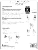
STEP 1
Locate the boundary lines to your property.
STEP 2
Drive stakes into the ground along the property line and stretch a string taut between each stake. Extend the string
approximately 24” beyond the end of the property line (Fig. 1). It is recommended that all posts be set approximately
6” inside of the property line so that the post footings do not encroach onto the adjoining property.
STEP 3
Mark the location of each terminal post with a stake (end posts, corner posts and gate posts are called terminal
posts). When determining the location of gate posts, refer to the chart on reverse side for actual gate opening sizes.
NOTE: If you are using flanged posts to mount your fence onto concrete or wood, use a chalk line instead of a string line
to mark the fence line. Anchor the flanged posts with MA250 masonry anchors (on concrete) or lag screws (on wood).
n
2
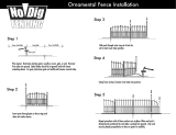
Installing Fence Over Sloped Terrain
If you are installing your fence over sloped terrain,
there are two options.
A. STEPPING THE FENCE PANELS (Special Order)
All styles can be stepped to follow the slope of
the terrain (Fig 2). When laying-out a stepped
installation, putting the posts closer together
will lessen the gap below the fence on the low
end of the slope.
B. ADjUSTABLE PITCH FENCE PANELS
Columbia style fencing is available in adjustable pitch panels (special
order) which allow you to adjust the panel to follow the slope of the
terrain (Fig. 3). When laying-out adjustable pitch fence panels over a
sloped terrain, measure your post spacing following the slope.
NOTE: For a stepped installation you will need to use longer posts.
n
3
Setting Your Terminal Posts
Although post depth and hole diameter will be determined by local weather and soil
conditions, holes for terminal posts and line posts are typically dug 8” in diameter,
18”-24” deep with sloped sides (Fig. 4).
STEP 1
Dig all terminal post holes.
STEP 2
Position the post in the hole. The post should be centered in the hole and must be
square with the fence line so that the sides of the post parallel the string line. Check
the post on the two adjacent sides with a carpenter’s level and adjust as necessary
so that it is plumb. The height
of the fence above the ground
is determined at this time as
well. Refer to the chart on
reverse side.
STEP 3
Pour concrete around the post,
fill to 2” below ground level. You
may need to tie off the posts using stakes and string to keep them from moving while the concrete cures. Once the concrete
is completely dry, fill the remainder of the hole with dirt.
STEP 4
After the terminal post footings have hardened enough to remain stable, stake and stretch a string line taut across the tops
of the posts on each end of the fence line to designate the desired height of the line posts (Fig. 5).
Sample Fence Layout
HOUSE
PROPERTY LINE
PROPERTY LINE
PROPERTY LINE
GATE
P PPP
P
P= Post
P
P P
n
4
Locating and Setting Your Line Posts
STEP 1
Working along the string line, stake out the position of all line posts. If your line of fence does not work out to even
increments of standard fence sections, you will need to trim a fence panel to fit the odd spacing on the end. If this
becomes necessary, consider trimming an even amount off of each end of the panel so that the space from the last
picket to the post remains consistent (Fig. 6). For aesthetic reasons, you may want to consider splitting the differ-
ence and trimming the panel on each end of your fence line, or trimming a portion off of each panel in your fence
line, so that all panels are the same size. Choose the option that works best and and position line posts accordingly.
STEP 2
Dig all line post holes.
STEP 3
Set all line posts as you did
the terminal posts, using
the string line at the top of
the posts to determine the
proper post height.
n
5
Hanging Your Fence Panels
If you cut fence sections, the length of the rails should be 1/2” less than the opening between posts. Cut ends must
be thoroughly cleaned, primed with a zinc-rich primer and painted with a high-quality rust inhibiting enamel paint to
ensure against corrosion of the exposed metal.
STEP 1
Place all four of the fence mounting brackets into the ends of the panel rails with the tabs facing downward.
STEP 2
Place the panel between the posts and align the top of the panel with the top of the post. Place blocks under the
panel to hold it at the desired height. Mark the location of the mounting holes in the four mounting brackets.
STEP 3
Remove the panel and drill 1/8” diameter pilot holes in the posts where marked.
STEP 4
Replace the fence panel (with the mounting brackets still in the rails) and secure to the posts with the screws provided.
n
6
Hanging Your Gates
The following instructions detail hanging a gate using a standard gate hardware
kit. If using another type of hardware, consult the installation instructions included
with that hardware.
STEP 1
On the hinge side of the gate, drill a 7/16” diameter hole 5” down from the top of the
gate and one 5” up from the bottom of the gate (Fig. 7). Remove the outer nut on both
hinge hanger bolts and adjust the inner nut so that when the bolt is inserted into the
holes you’ve drilled in the gate frame, approximately 1” or more of threads are exposed.
Replace outer nuts finger-tight and position the bolts so that the short end of the top bolt
points up and the short end of the bottom bolt points down. Tighten the outer nuts.
STEP 2
Position the gate in the opening and place blocks under the gate to achieve the de-
sired height. Remove the nut and bolt from one hinge hanger bracket and slip the
clamp onto the post. Position the hinge hanger bracket so that the bottom hinge
hanger bolt is well seated in the bracket. Replace the nut and bolt and tighten.
STEP 3
Repeat step 2 to attach the top hinge hanger bracket.
STEP 4
Adjust the gate to hang squarely in the opening using the nuts on the hanger bolts. For example, if the latching side
of the gate sags downward, “tighten” the nuts at the top or “loosen” the nuts at the bottom.
STEP 5
Position the gravity latch striker bar on the gate at the desired height (mount striker bar to the outside of the gate to
make the gate swing out, mount on the inside to make the gate swing in). Mark the position of the hole in the striker
bar mounting plate. Drill 1/8” inch pilot holes in the post where marked. Replace the striker bar and mount it to the
post with the screws provided.
STEP 6
Remove the nut and bolt from the latch. Slip the clamp onto the post and position it so that the striker bar engages
the latch smoothly. Replace the nut and bolt and tighten.
NOTE: For double gates, purchase two hardware kits: 1 gate hardware kit and 1 cane bolt. Mount the hinges and
latch as described above for single gates. Mount the striker bar to the gate which will be used primarily for opening
and entering. Mount the latch and the cane bolt to the gate which will be primarily stationary. Mount the cane bolt
as described on the back of the package.
n
7
Touch-Up and Clean-Up Of Installation
Clean material as necessary with a soft rag and mild soap to remove dirt and any concrete that may have splashed
onto the material. Rinse with clean water to remove all soap.
NOTE: First Alert products are constructed of steel for strength and durability. Due to the nature of steel, exposed, scratched
or scraped areas will rust. Immediately upon completion of your installation, clean, prime and paint all areas damaged dur-
ing handling and installation. Periodically check fence for signs of wear and oxidation and repaint as necessary.
4
5
1
6
7
3
2
/