Page is loading ...

FENCE
INSTALLATION GUIDE
6’ HIGH FENCE
1.866.648.9336 www.simtekfence.com

INSTALLATION GUIDE
These instructions are designed to assist both professional installers and do-it-yourselfers of SimTek™ decorative
rock-walls. These instructions are detailed to insure an excellent nished wall.
A quality nished wall is a result of a quality installation. The layout must be consistent with ground contours;
posts must be appropriately spaced and properly anchored. Follow SimTek™ installation instructions carefully and
your wall will be both structurally correct and a beautiful addition to your project or property.
Before any installation, check all local regulations regarding fencing, location of all buried utility lines, and correct
property lines. Be certain that you are in compliance will all local codes, permits, county and state laws. Ensure
that you have all the components needed to complete your fence conguration.
Tape Measure
Level
Auger or Post Hole Digger
Shovel
Power Drill
Circular Saw
Concrete
Spray Paint
Mallet or Hammer
Fence String
TOOLS NEEDED

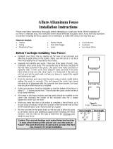
Step 1: Lay Out Fence Line
1. Locate your property line and stretch a string between stakes from
the beginning to the end of the fence to ensure posts will be set on
a straight line.
2. Beginning at the corner or end post, mark the location of the post.
Dig a hole for each post.
House
Center to Center Post Dimensions
Line Corner End Gate
71 ½” 72 ½” 71 ½” 72 ½”
73 ½” 72 ½” 73 ½”
Line
Corner
Step 2: Digging Holes
1. If a laser is available, it will be an excellent tool to assist in determining
grade and slope.
2. For a level ground installation, begin at a corner or an end post. This will
give you a good starting point. If there is a slope, it is easier to begin at the
top and work your way down hill.
3. Dig all post holes 10″- 12″ diameter by 30″- 36″ deep for the six foot high
wall and 48” deep for the eight foot high wall. Make sure to check local
building codes to ensure required depths and diameters are met.
4. Holes must be 71.5″ apart, center to center for the six foot wall and 96” for
the eight foot wall. It is essential that the panel stiffener touches post to
post. The panel stiffener is wider than the panel to accommodate panel
thermal expansion. DO NOT CUT THE STIFFENER UNLESS THE
PANEL IS BEING CUT SHORTER.
5. Walls will rarely measure out to an exact number of full panels; therefore it
will likely require cutting one or more panels to complete a wall.
Depending on personal preference, you may wish to narrow the width of the
last 2 to 3 panels or cut the rst and last panels evenly so that there is not one
very narrow panel. Panels can be cut with any circular saw, although the
steel stiffeners will require a metal cutting blade.

Step 3: Installing Fence Brackets
If posts are to be installed in level ground attaching brackets in advance
of post installation is easiest when using a measuring template for
faster repetitive bracket installation. It is easier to change a bracket in
the eld if necessary than to install brackets once posts are installed in
the ground.
Installed brackets provide a leveling point on each post.
DISTANCE FROM TOP OF POST TO SUPPORT BRACKET SURFACE
3’ 4’ 6’ 8’
37.5” 49.5” 73.5” 99”
Panel Size
Bracket
location
Tip
Note: Brackets come packaged at the tip of the
post during shipping. They must be removed and
reattached in the channel of the post at the desired
height during installation.
Step 4: Setting Posts
1. Set a post in the hole with concrete. Using a mallet or hammer, tap the post
into the concrete until the top of the post meets the desired height.
2. Fill the remainder of the hole with concrete. Using a level, check two adjacent
sides of the post. Two-way levels are useful. Adjust the post until it is both vertical
and at the correct height.
3. If using a dry mix method, rst place the post in the hole in the approximate
position at the bottom of the hole. Pour the dry mix in the hole, positioning the post
as soon as it is feasible.
4. Using the steel stiffener out of the panel, which is exactly 70.25″ for the six foot
wall and 95” for the eight foot wall, as a spacer, set the next post the same as the
rst.
5. Do not move the post which is now in position. Leave the panel stiffener spacer in
place for one hour minimum, as concrete begins to cure, to keep the posts from
moving. Set 3 to 4 posts with panel stiffeners as spacers, then advance them one at
a time, by moving the rst spacer placed. Allow the concrete to cure for a
minimum of 24 to 48 hours.
6. For a complete step-by-step installation video, visit our website at:
http://www.simtekfence.com/product-information or for personalized assistance
call our customer service line at 1-866-648-9336.
Make sure post is straight, plumb, and evenly spaced
Tip
Note: All SimTek posts are reinforced with galvanized steel. If posts need to be cut,
we suggest cutting them at the tip. Do not cut the top of the post.

Step 5: Installing Fence Panels
1. Panel support brackets must be attached to all posts.
2. Be certain steel stiffeners are inserted in the top and
bottom rail of each panel; they come installed from the
factory, but may have been removed to use as post spacers.
3. Panels are universal, with no front or back, and no top
or bottom edge. Randomly installing panels gives the most
pleasing aesthetic effect.
4. Lift the panel bottom edge to approximately 4’ off the
ground. Have one person ex the next post outward until
the groove will receive the panel. Once the section is in the
channel, ease the panel down onto the support brackets.
5. Install caps over the posts.
6. Caps are pressure tted making securing them typically
unnecessary; however, a 3” screw can be driven through the
top of the cap into the middle of the post if desired.
Step 6: Securing Panels
1. Panels must be attached to all six foot gate posts
and corner posts because they could conceivably
become disengaged from the post because of the
shallower groove.
2. To prevent unauthorized panel removal, you can
drive one fastener per panel through the panel
edge into the post.
3. Caution. Never attach both edges of any panel to
posts. Polyethylene has a degree of thermal
expansion and contraction.
#14 Hex Washer Head, 3”
Self Tapping Screw
Fasteners should attach
panels to end post and
corner post inside panel
grooves
Tip
Note: Never attach both edges of any panel to posts. Polyethylene has a degree of
thermal expansion and contraction.

Step 7: Cutting Panels
Where a narrower panel is required to nish a wall, pan-
els can be cut to any desired length.
1. Remove steel stiffeners from panels. Determine the
exact width between post channels. Mark and cut
stiffeners to that width with a metal cutting blade.
2. Mark and cut the panel to the stiffener width, minus
½” to allow for thermal expansion and contraction of
the panel. Make certain panels are cut accurately
with edges parallel.
3. If a cut panel is used with an end or corner post, use
the factory edge for attachment to the post.
4. For steeper slopes, panels can be cut so the step or
drop in each section is 12” or less.
Installing on a Retaining Wall
SimTek can be installed on top of an 8” minimum width poured concrete wall or on at
concrete using SimTek’s Concrete Mounting Brackets. Concrete surface mounts are
manufactured with a heavy steel plate with vertical members. It attaches to the con-
crete with anchors and bolts to the post. Specic concrete shoes are available for end
post, line post and corner posts.
1. Cut the post to the desired height. Post may need to be cut longer to accommodate
changes in elevation. Always cut off the bottom of the post, retaining the factory
nished post top.
2. Panel support brackets are unnecessary when using concrete shoes. The Panels
will set directly on the wall or driveway surface.
3. Start at the corner or an end post position. Locate the concrete shoe an equal
distance from the edges of the concrete.
4. Mark the position of the plate. Drill all four
holes through the pre-drilled holes in the steel plate.
5. Next install all the concrete anchor bolts in the
base plate bolt holes provided with a minimum
tension and shear strength of at least 4,000 lbs.
Position the bolts to fasten the mounting place
of the shoe.
6. Place the shoe over the bolt and attach the
shoes to the concrete with specied fasteners

7. If the concrete is not level, washers may be placed over anchor bolts and before shoes are bolted down to serve as
leveling devices.
8. Position the skirt covers over the shoes, covering the metal plates. Skirts must be inserted prior to posts being attached.
9. Attach the shoe straps to the posts with fasteners in pre-drilled holes. Each side of the strap gets three staggered screws
installed from opposite sides of the post for line posts and three each for ends and corners.
10. With the rst shoe anchored, and the post attached, determine and mark the next shoe position using a panel stiffener
as a spacer. It will measure 71.5” (for 3’ high and 6’ high) from the center of the next post and 1” shorter for a line to
a corner post. For 4’ high and 8’ high sections, it will measure 96” center to center.
11. Cut 7/8” of the bottom panel stiffer to accommodate the shoe strap and its screws. It is also recommended to remove
½” off the lower two feet on both sides of the panel edge to accommodate the shoe straps as well.
12. Mark and drill the holes for the next shoe.
13. Once all the shoes and posts are securely anchored to the wall and skirts are in place, insert the panels. Be certain that
steel stiffeners are in both top and bottom rails of each panel.
14. Finally, place the caps on the post for a nished look.
Concrete Surface Mounting Brackets

Installing on Sloping Terrain
Caution: SimTek Fence is not engineered
for use as a retaining wall.
Installation on sloping terrain is similar to that on at terrain. Pro-
fessionals typically use a laser to shoot and obtain a grade.
1. Set the rst post on the uphill side. Post placement is
important! Posts are typically placed at the point where the
slope changes whether in a peak or a valley.
2. The panel support brackets should be pre-attached at 73
½” for 6’ high or 98” for 8’ high and can receive the down
hill side of the panel at that height. Once the slope and
the drop per panel have been determined, the bracket on the
uphill side should be adjusted to the proper height. Panels
will always be set level even on a slope.
3. Set the second post and make any adjustments to bracket
position.
4. Use steel stiffeners for spacing to set the distance for each
succeeding post.
5. Use a level on the stiffener to insure panels will be level
when installed.
6. For more information see illustration A and B
7. Please visit our website for a full installation video
http://www.simtekfence.com/install/
FYI
A 6’ wide panel can be stepped as much as 12” per panel. For steeper elevations you can
use our 142” long post. For more details and instructions call your sales representative

SimTek Gate Installation Guide
Gate Components and Tools Needed
Gate Post
SimTek™ Fence Gate
End Post
SimTek™ Hinges
Latch
Striker Rod (optional)
2 ½” Self-tapping Screws
Button Head Screws
Level and Power Drill
Concrete
Step #1: Set the Gate Post
Gate posts have extra steel reinforcing for strength and are different than all
other posts. Before setting the post in the ground, make sure that a gate post
(not an end post is used)
1. Dig a hole 10” to 12” in diameter by 30” to 36” deep in the ground.
2. The at surface (without a channel) must be in position to receive the gate
and gate hardware.
3. Post spacing is critical. The ideal spacing is to have a 1” gap between the
latch post and the striker bar side of the gate and 1 ½” for the hinge side.
The extra gap on the hinge side is to allow for thermal expansion and con
traction.
4. Set the post utilizing the same method as for other posts and ll the hole
with concrete. Allow the concrete to cure for 48 to 72 hours.
Gate Post
End Post
(Hinges are attached to this post)
(The latch is attached to this post)
(inside-to-inside post spacing)

Step #2: Gate Openings
All gates require about a 1 ½” gap between the gate and the gate post, and about a 1” gap between the gate
and the end post or between the two gates when using double gates.
For a single gates, use one gate post and one end post. For double gates, use two gate posts.
Gate Post End Post
Inside-to-Inside Post Spacing
(see table below)
SimTek Gates
3ft Wide Gate
4ft Wide Gate
5ft Wide Gate
6ft Wide Gate
Gate Width
38.5”
50.5”
62.5”
73.5”
Single
Opening
76.0”
88.0”
99.5”
110.5”
Double Drive
w/3’ Gate
88.0”
100.0”
111.5”
123.5”
Double Drive
w/4’ Gate
100.0”
112.0”
122.5”
134.5”
Double Drive
w/5’ Gate
112.0”
124.0”
134.5”
145.5”
Double Drive
w/6’ Gate

Step #3: Gate Hardware Installation
A. Thread the ½” hinge rod into the upper and lower inserts in the gate metal
frame leaving about 1 ½” from the edge of the gate to the bracket (this can
be re-adjusted later)
B. Next hold the gate and its hinges against the gate post at the proper position
and height. Drill the provided 2 ½” self-tapping screws into the gate post.
Do not over tighten the screws because it can crush the
internal foam, making an indentation in the post.
C. Level the gate. The standard height should be level with the top of the fence
panel. Gates are designed with a 4” gap at the bottom to facilitate an un
obstructed swing. If you desire a gap smaller than 4”, you may lower the
gate relative to the fence panels.
D. Attach the striker rod to the gate by using the provided button head screws.
E. Finally, align the latch with the striker rod and attach the latch to the end
post by using the supplied 2 ½” self-tapping screws.
Internal
Metal Frame
Illustration A
Hinge
Gate Panel
2 ½” Zinc Plated Self Tapping Screw
SimTek Hinge
Striker Rod
Button Head Screw
Latch
2 ½” Zinc Plated Self Tapping Screw
1.866.648.9336 www.simtekfence.com
!

SimTek™ Fence warrants the product line to be free from manufacturing defects in materials and workmanship for 25-years from
the date of purchase, or for as long as the original end-user purchaser of the product owns and occupies the real estate on which
the product was rst installed. The manufacturer’s warranty does not apply to installation.
What We Cover. When proper installation procedures are followed and under normal and proper use, SimTek™ Fence will
not crack, warp, peel, rot, blister, fade or drastically change colors. If such defects or degradation is discovered, SimTek™ at its
sole discretion will repair, replace the product, or provide the customer a credit for the value of the product subject to the warranty
within a reasonable time following the receipt by SimTek™ Fence of notice of such a defect.
Limitations and Exclusions. This warranty does not cover damages as a result of abuse, misuse, vandalism, unauthorized
repairs or modications, defacement, neglect, accidents, improper installations, or improper use, acts of god, improper ground
settlement, failure of any structure or soil in which the fence was installed, exposure to extremely harmful chemicals, re, etc.
SimTek™ will not be responsible for labor or other expenses not directly incurred by SimTek™ in effecting any claims under this
warranty.
SimTek™ reserves the right to modify, enhance, discontinue its products, including colors and will not be responsible in the event
replacement products vary in granite colors compared to the original product as a result of reasonable weathering and/or product
engineering.
Registration. In order to receive full benets on this warranty, you must register your warranty within 90 days of installation by
completely and accurately lling out our online warranty registration at our website: www.simtekfence.com/registration/
WARRANTY INFORMATION
Toll Free 1.866.648.9336
Tel. 1.801.655.5236
Fax 1.801.655.5240
www.simtekfence.com
Since 2007
/