Toro Light Kit (10 Colonial and 80 Watt Power Pack) User manual
- Type
- User manual
This manual is also suitable for
- Light Kit (10 Tier Path and 80 Watt Power Pack)
- Light Kit (12 Contemporary and 84 Watt Power Pack)
- Light Kit (12 Tier Path and 84 Watt Power Pack)
- Light Kit (6 Contemporary, 4 Variable Focus and 72 Watt Power Pack)
- Light Kit (6 Tier Path and 56 Watt Power Pack)
- Light Kit (6 Variable Focus and 56 Watt Power Pack)
Page is loading ...

2
TORO
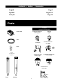
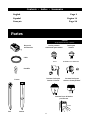
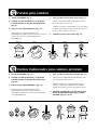
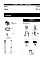
Fixtures
(Type depends on kit purchased)
Power Pack
Cable
Bulbs
Flood
Pathway
Stakes
(Type depends
on fixture)
Premium Traditional
Pathway Light
Premium Varifocus
®
Floodlight
Floodlight
Premium Colonial
Pathway Light
Premium Wood
Deck Light
Premium Contemporary
Pathway Light
Pathway
Lights
Parts
English Page 2
Español Pagina 14
Français Page 26
Contents • Indice • Sommaire

3
IMPORTANT:
• For use with landscape
lighting systems only.
• The device is accepted as a
component of a landscape
lighting system where the
suitability of the combination
shall be determined by CSA
or local inspection authorities
having jurisdiction.
• Do not connect two or more
power supplies in parallel.
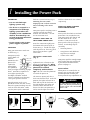
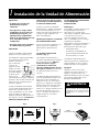
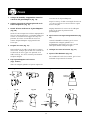
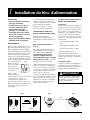
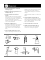
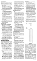
LOCATION
Hang your Toro Power Pack near
an outlet (Fig. 1).
Toro power packs
with a photo cell
must be
mounted so the
photo cell is
exposed to
natural light.
This photocell
shuts your lights off during daylight
hours. Avoid direct exposure to
street lights, porch lights,
headlights and other artificial
sources of light because this may
cause your system to shut off.
Hang the power pack (screw
provided) at least one foot (30 cm)
above the ground, making sure the
cord can reach the outlet. Make
sure the power pack is mounted
flush on a vertical surface (Fig. 2).
Mounting the Power Pack
improperly can result in corrosion
and overheating to the Power
Pack.
Your power pack’s cord plugs into a
120-volt covered GFCI outlet
marked “Wet Location.”. Do not
use an extension cord.
CONNECT THE CABLE TO
YOUR TORO POWER PACK.
Insert the connectors tightly into
the bottom of the power pack as
shown in Fig. 3. Install each light
with the power on. That way you’ll
know when you have a good
connection.
The VariSet™ Power Pack
(Fig. 4)
A photoelectric cell turns on the
power pack automatically. When
installing your lights, cover the
photoelectric window
completely with thick dark
tape. This will cause the photocell
to switch the power on.
The VariSet™ power pack has a
slide switch on the back. In the left
position, the lights will turn on at
dusk and stay on for four hours. In
the right position, the lights will
turn on at dusk and turn off at
dawn. The other two positions (6,
and 8) turn the lights on at dusk
and leave them on for 6 or 8 hours,
respectively.
WHAT YOU NEED TO KNOW
ABOUT POWER PACKS
Overloads
Power packs have built-in overload
protection. If an overload occurs,
your power pack will shut off and
not turn back on for 5 to 20
minutes. If not corrected, the
power pack will keep cycling on
and off. Overloading may be
caused by:
• Too many fixtures.
• Using fixtures with bulb wat-
tages that are too high.
• A short in the cable.
Your power pack has enough output
for the lights that came with this kit.
If you want to add more fixtures,
please read page 11.
Power Failure
When power is restored after an
outage, your system will resume
normal operation without you
having to make any adjustments to
1 Installing the Power Pack
To avoid electrical shock, do not
open the power pack housing.
There are no user-serviceable
parts inside.
WARNING
Fig. 2 Fig. 3 Fig. 4
TORO
Fig. 1
photocell
Yes
No

4
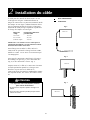
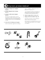
! Overloading the Cable or a Cable Connector
Can Cause Fire !
• Overloading a cable connector will cause overheating and
can cause fire if near combustible materials.
• Never bury the cable in combustible materials such as wood
chips, bark, dried leaves, etc.
WARNING
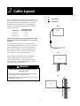
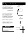
2 Cable Layout
There are two ways to lay out your cable: in a single
line or in branching lines using cable connectors. The
total lamp wattage on a branching line affects the
length of the line you can have. The maximum
length of cable per line depends on the lamp-load
wattage on that line.
Maximum Cable
Lamp Load Length per Branch
0–40 watts 250 feet
40–72 watts 150 feet
98 Watts & up 100 feet.
IMPORTANT: EXCEEDING THE RECOMMENDED CABLE
LENGTH WILL RESULT IN DIM LIGHTS AT THE END OF
THE LINE.
For adding or splicing cable, use a TORO model
52914 outdoor lighting system connector. Be sure to
read and follow the cable connector instructions.
Three types of connections are shown below: An
inline extension (Fig. 5), a T-branch connection
(Fig. 6) and a four-way connection (Fig. 7).
Always bury the cable and connector about four
inches underground after you have finished
connecting your lights. Do not bury the cable or
cable connectors in combustible materials such as
wood chips, bark, dried leaves, etc.
Power Pack
Connector
Fig. 5
Fig. 6
Fig. 7
Home
Home
Home

5
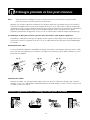
The most important part of installing the fixtures is making sure their metal pins pierce
the wire inside the cable. Make sure the piercing points are straight before you press
the cable into them. Use a screwdriver to straighten points if they are misaligned.
Correct Piercing Points
Misaligned Piercing Points
This
Not This
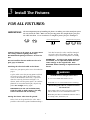
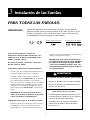
IMPORTANT:
FOR ALL FIXTURES:
3 Install The Fixtures
Connect fixtures to 16-gauge or 18-gauge SPT-3
low-voltage outdoor lighting cable only.
Recommended spacing of fixtures: at least five
feet.
Do not install the fixtures within ten feet of a
pool, spa, or fountain.
Attaching the electrical cable to the fixture.
Make sure your power pack is on as described on
page 3.
Lay the cable across the piercing points and slide
the stake over the cable in the direction of the
arrow on the bottom of the fixture. If you have
done this correctly, the fixture will light. If it
doesn’t, make sure the power pack is on (and the
photocell is covered to block light), the piercing
points are straight, and try again.
IMPORTANT: Do not cut insulation away
from the cable to make contact. This may
lead to corrosion and overheating.
Putting the fixture stake into the ground.
Make a hole in the ground for the stake. Don’t
push the stake into the ground without making a
! Lit bulbs are hot enough to burn skin !
• Do not remove bulbs while fixtures are on.
• Allow bulbs to cool several minutes before touching.
! Overloading the Cable or a Cable Connector
Can Cause Fire !
• Overloading a cable connector will cause overheating
and can cause fire if near combustible materials.
• Never bury the cable in combustible materials such as
wood chips, bark, dried leaves, etc.
WARNING
hole first because the stake could be damaged.
Insert the stake, fill around it with dirt. Do not
hammer or press on the lamp fixture assembly.
IMPORTANT: To ensure your power pack isn’t
overloaded, use a replacement bulb with the
same wattage as the original bulb. Note:
Maximum allowed wattage is imprinted on the
fixture.

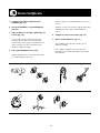
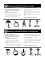
6
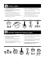
1. Install the light bulb (Fig. 8).
2. Firmly center the cable straight over the
piercing points (Fig. 9).
3. Attach the stake to the fixture (Fig. 10).
Slide the closed stake onto the fixture base,
locking the cable against the contacts (follow the
arrow direction on the fixture).
4. Run the cable through the stake (Fig. 11).
Open the stake by pinching together the locking
tabs near the base of the stake.
Fold the cable into each side of the stake. Align
the cable with the notches at the bottom of the
stake and snap the stake closed.
5. Put the stake into the ground (Fig. 12).
Pathway Lights
Fig. 8 Fig. 9 Fig. 10 Fig. 11 Fig. 12
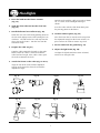
1. Install the light bulb (Fig. 13).
2. Firmly center the cable straight over the
piercing points (Fig. 14).
3. Attach the stake to the fixture (Fig. 15).
Slide the closed stake onto the fixture base,
locking the cable against the contacts (follow the
arrow direction on the fixture).
Premium Traditional Pathway Lights
4. Run the cable through the stake (Fig. 16).
Open the stake by pinching together the locking
tabs near the base of the stake.
Fold the cable into each side of the stake. Align
the cable with the notches at the bottom of the
stake and snap the stake closed.
5. Optional: Removing Traditional Pathway
Light middle tier (Fig. 17 & 18).
Fig. 13 Fig. 14 Fig. 15 Fig. 16 Fig. 17 Fig. 18

7
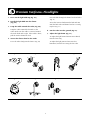
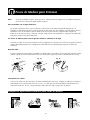
1. Press the bulb into the fixture contacts
(Fig. 19).
2. Snap the silver reflector into the clear lens
(Fig. 19).
3. Install the fixture lens/reflector (Fig. 20).
Install the clear lens/reflector by pushing down on
the lens with slight pressure while turning the lens
clockwise. The tabs on the lens will snap into the
three slots on the fixture. Turn the lens until the
movement stops.
4. Prepare the stake (Fig 21).
Loop the cable around the channels in the stake.
Make certain the cable is centered around the
stake head and is tight. If the cable is loose, pull
the ends to eliminate the slack.
5. Attach the fixture to the stake (Fig. 22 & 23).
Align the side of the stake with the imprinted
triangle to the top of the fixture head with the
imprinted triangle.
Hold the stake with the cable at an angle of about
30° (1 o'clock) to the floodlight housing as
shown.
Press the stake with the cable down firmly into
the piercing points on the fixture.
6. Lock the stake in place (Fig. 24).
After the fixture has lit, turn the stake away from
the imprinted triangle on the fixture to lock it in
place. Pull on the cable to remove any slack.
7. Put the stake into the ground (Fig. 25).
8. Adjust the light beam (Fig. 26).
To adjust the light beam from narrow to broad,
turn the lens using the tabs.
Floodlights
Fig. 19 Fig. 20 Fig. 21 Fig. 22
Imprinted
triangles
1
o'clock
Imprinted
triangles on
the stake
and the
fixture
Fig. 23 Fig. 24 Fig. 25 Fig. 26

8
TORO
1. Press on the light bulb cap (Fig. 27).
2. Install the light bulb into the fixture
(Fig. 28).
3. Loop the cable around the stake (Fig. 29).
Loop the cable around the channels in the
stake. Make sure the cable is centered around
the stake head and is tight. If the cable is loose,
pull the ends to eliminate slack.
4. Secure the fixture head to the stake.
Press the stake firmly into the fixture (Fig. 30)
Insert the bolt through the fixture head and stake
(Fig. 31).
Screw the fastener knob onto the bolt and turn
until the bolt stake and fixture head are securely
in place (Fig. 31).
6. Put the stake into the ground (Fig 32).
7. Adjust the light beam (Fig. 33).
To adjust the light beam from narrow to broad,
turn the focus ring.
To adjust the light pattern from vertical to
horizontal, turn the lens using the lens tabs.
2
3
1
Premium Varifocus
©
Floodlights
Fig. 27 Fig. 28 Fig. 29 Fig. 30
Fig. 31 Fig. 32 Fig. 33

9
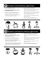
Premium Colonial Pathway Light Fixture
1. Install the light bulb (Fig 34).
2. Firmly center the cable straight over the
piercing points (Fig. 35).
3. Attach the stake to the fixture (Fig. 36).
Slide the closed stake onto the fixture base.
(Follow the arrow direction on the fixture.) This
locks the cable against the contacts.
4. Run the cable inside the stake.
Open the stake by pinching together the locking
tabs near the base of the stake (Fig. 37).
Fold the cable into each side of the stake. Align
the cable with the notches at the bottom of the
stake and snap the stake closed.
Snap on the black cover by pushing it straight
down onto the lens.
5. Put the stake into the ground (Fig. 38).
Fig. 34 Fig. 35 Fig. 36 Fig. 37 Fig. 38
Premium Contemporary Pathway Light Fixture
1. Install the light bulb (Fig. 39).
2. Firmly center the cable straight over the
piercing points (Fig. 40).
3. Attach the stake to the fixture (Fig. 41).
Slide the closed stake onto the fixture base.
(Follow the arrow direction on the fixture.) This
locks the cable against the contacts.
After the stake is attached, attach the black cover
to the top of the fixture. Rotate the cover until the
locking tabs on the lens snap into place on the
cover.
4. Run the cable inside the stake (Fig 42).
Open the stake by pinching the locking tabs
together.
Fold the cable into each side of the stake. Align
the cable with the notches at the bottom of the
stake and snap the stake closed.
Snap on the black cover by pushing it straight
down onto the lens.
5. Put the stake into the ground (Fig. 43).
Fig. 39 Fig. 40 Fig. 41 Fig. 42 Fig. 43

10
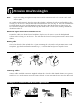
Note: Before assembling your lights, you may want to seal the wood parts with a clear exterior sealer, wood
stain or paint.
To assemble with the top only: fasten the top to the backplate, and fasten the reflector and backplate to the
rail using 5/8-inch screws. Run the cable out of the channel on either side (Fig. 44). You can also mount the
Deck Light flush on a rail or wall by flipping the top of the other side of the backplate as shown in Fig. 45.
First attach the backplate and reflector to the top, then mount with 5/8-inch screws, running cable out the
channel on either side.
Wood Deck Lights can also be used without the top:
Position the cable in the channel on the backplate and place it in the corner. Fasten the backplate and
reflector to the rail using 5/8-inch screws. The cable must be fastened securely to prevent the contacts from
damage.
Connecting Cables
Connect cables with cable connectors supplied with your kit. Place the cable from the fixtures in the groove
marked “18 GA.” and the power pack in the groove marked “16 GA.” Now put the cover over the cables and
fasten with a screw.
Routing Cable
The lens has break-off tabs on both sides. If you are running the cable out the side, you must remove a tab.
Using pliers, grip the tab and bend it outward (Fig. 46). It will break off and you can snap the lens on.
Premium Wood Deck Lights
Examples of Versatile Wood Deck Applications
Fig. 44 Fig. 45 Fig. 46

11
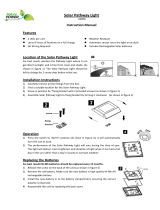
Your power pack has enough output for the lights that
came in your kit However, you can add fixtures to
some kits. Also, you can increase the bulb wattage to
some fixtures (see each fixture for the maximum bulb
wattage it will handle). Just make sure the total lamp
load doesn’t exceed your power pack’s output rating.
Your power pack’s maximum OUTPUT is listed on the
front above the model number:
To find out your lamp load, add the bulb wattages of
your fixtures. EXAMPLE: Ten fixtures, each with
7-watt bulbs = 70-watt lamp load.
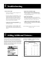
Maximum number of lights
for each type of power pack:
Maximum Output Bulb Wattage
4 7 12 18
Maximum number of lights
21 watt 5 3 1 1
36 watt 9 5 3 2
40 watt 10 5 3 2
49 watt 12 7 4 2
56 watt 14 8 4 3
72 watt 18 10 6 4
80 watt 20 11 6 4
84 watt 21 11 6 4
98 watt 24 14 8 5
152 watt 38 21 12 8
160 watt 40 22 13 8
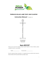
Power Pack
Bloc D’alimentation
Paquete de Energía
CAUTION: SUITABLE FOR OUTDOOR USE ONLY
USE ONLY TORO TYPE T-5 BULBS RATED 18W MAXIMUM
MOUNT AT LEAST 30 CM (1 FOOT) ABOVE GROUND.
Input: 120 V 60 Hz 1.0 A Output: Max XXX W 12 V AC lamp load
Not for use with a dimmer
ATTENTION: POUR UTILISATION A L'EXTERIER SEVLEMENT
UTILISER SEULMENT DES AMPOULES TORO DE TYPE T-5
INSTALLER A AU MOIN 30 CM AU-DESSUS DU SOL.
Energlo d''entré: 120 V 60 Hz 1.0 A Puissance de sortie:
XXXW Max charge de lampo 12 V C.A.
Ne pas utilliser avec un régulateur de tension
PRECAUCION: APTO SOLAMENTE PARA USO EN EXTERIORES
USE SOLO BOMBILLAS TORO TIPO T-5 CON CAPACIDAD
COLOCAR POR LO MENOS A 30 CM (1 PIE) DEL SUELO
Entrada: 120 V 60 Hz 1.0 A Salida: Max XXX W 12 VCA
carga de bombillas. No user con un atenuador de corrienta.
SERIAL NUMBER/NUMERO DE SERIE:
Model/ModelModèle: 1 2 3 4
®
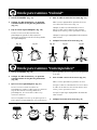
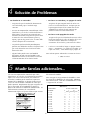
• Fixtures do not light
– Make sure your power pack is plugged in and
your outlet is working.
– You have a photo-cell controlled timer. If it is
daylight, the photo cell must be covered with
tape or other material to simulate darkness.
Make sure the tape or material is heavy and
dark so that no light gets through. The tape
must be removed after installation.
– Contact points in the fixture may be bent.
Straighten the contacts to align with the copper
wire inside the cable.
– A fixture might have a defective bulb. Test by
using another bulb. A defective bulb in one
fixture will not affect the operation of the other
fixtures.
• Lights turn on and off at night.
Make sure a fixture from your lighting set is not
facing your photo cell. See if other light sources
(such as headlights or reflections from a window)
are triggering the photo cell.
• Lights stay off at night.
Make sure the photo cell isn’t getting light from a
street light, porch light or other light sources. Check
connections in the fixtures or cable connector.
• Lights go on, then shut off for about 5–20
minutes, then go on (and the cycle repeats).
See Overloads, page 3.
To order additional parts or for technical assistance:
1 (800) 321-8676
5 Adding Additional Fixtures...
4 Troubleshooting

12
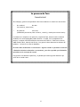
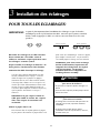
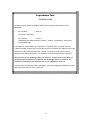
The Toro Promise
A Full Warranty
The Toro Company warrants this TORO Product against defects in material or workmanship.
The following time periods apply from date of purchase.
• Standard Light Kits Two years
(Pathway Light and Floodlight fixtures)
• Premium Light Kits Five years
(Traditional Pathway, Varifocus
©
, Colonial, Contemporary, and Wood Deck fixtures)
To receive a replacement or repair, at Toro’s option, just return the defective component
(light fixture, power pack or wire), postage prepaid, to the seller or the TORO Service Center,
5300 Shoreline Blvd., Mound, MN 55364 along with proof of purchase. This warranty covers
product defects only. Warranty excludes bulbs.
The Toro Company is not liable for indirect, incidental or consequential damages in
connection with the use of TORO products covered by this warranty. Some states do
not allow the exclusion or limitation of Incidental or consequential damages, so the
above limitation may not apply to you.
This warranty gives you specific rights, and you may have other rights, which vary from state
to state.

13
®
When You Want It Done Right™
Page is loading ...
Page is loading ...
Page is loading ...
Page is loading ...
Page is loading ...
Page is loading ...
Page is loading ...
Page is loading ...
Page is loading ...
Page is loading ...
Page is loading ...

25
®
When You Want It Done Right™

26
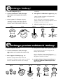
TORO
Eclairages
(Le type dépend du kit acheté)
Bloc
d'alimentation
Câble
Ampoule
Projecteur
Pour Allées
Piquets
Le type dépend de l'éclairage)
Eclairage premium
traditionnel Pathway™
Projecteur premium
Varifocus®
Projecteur
Eclairage premium
olonial pour allées
Eclairage premium en
bois pour terrasses
Eclairage premium
contemporain pour allées
Eclairages Pathway™
Pièces
English Page 2
Español Pagina 14
Français Page 26
Contents • Indice • Sommaire
Page is loading ...
Page is loading ...
Page is loading ...
Page is loading ...
Page is loading ...
Page is loading ...
Page is loading ...
Page is loading ...
Page is loading ...
Page is loading ...
-
 1
1
-
 2
2
-
 3
3
-
 4
4
-
 5
5
-
 6
6
-
 7
7
-
 8
8
-
 9
9
-
 10
10
-
 11
11
-
 12
12
-
 13
13
-
 14
14
-
 15
15
-
 16
16
-
 17
17
-
 18
18
-
 19
19
-
 20
20
-
 21
21
-
 22
22
-
 23
23
-
 24
24
-
 25
25
-
 26
26
-
 27
27
-
 28
28
-
 29
29
-
 30
30
-
 31
31
-
 32
32
-
 33
33
-
 34
34
-
 35
35
-
 36
36


Toro Light Kit (10 Colonial and 80 Watt Power Pack) User manual
- Type
- User manual
- This manual is also suitable for
-
- Light Kit (10 Tier Path and 80 Watt Power Pack)
- Light Kit (12 Contemporary and 84 Watt Power Pack)
- Light Kit (12 Tier Path and 84 Watt Power Pack)
- Light Kit (6 Contemporary, 4 Variable Focus and 72 Watt Power Pack)
- Light Kit (6 Tier Path and 56 Watt Power Pack)
- Light Kit (6 Variable Focus and 56 Watt Power Pack)
Ask a question and I''ll find the answer in the document
Finding information in a document is now easier with AI
in other languages
Related papers
-
Toro Metal Tier Path Light (52606) and 80 Watt Power Box Installation guide
-
-
-
-
-
-
-
-
-
Other documents
-
 Lumabase 61308 Operating instructions
-
 Nature Power 21072 Owner's manual
-
 Kichler Lighting 15578BK User manual
-
 Utilitech SP-049 User manual
-
 Nature Power 23107 Owner's manual
-
 Nature Power 23107 Owner's manual
-
 Gama Sonic GS-105PL880 Installation guide
-
dewenwils HOYS22M User manual
-
Portfolio EE3394BK User manual
-
 Hampton Bay HD172789 Installation guide


