Pentek PENTEK-150166 User manual

Category
Sanitary ware
Type
User manual
Water Filter
Installation and Operating Instructions
Specifications
Tools Required
Screwdriver File Pipe Cutter or Hacksaw
2 Adjustable Wrenches Pencil
Materials Required
Depends on type, size, and location of pipe on which system will be installed. See instructions that relate to your
particular installation, or consult your local hardware store or plumbing supplier to find out more about your particular
installation needs.
Precautions
WARNING: Do not use with water that is microbiologically unsafe or of unknown quality without adequate disinfection
before or after the system.
CAUTION: Filter must be protected against freezing, which can cause cracking of the filter and water leakage.
CAUTION: The rubber o-ring provides the water-tight seal between the cap and the bottom of the housing. It is important
that the o-ring be properly seated in the groove below the threads of the housing, or a water leak could occur.
CAUTION: To prevent costly repairs or possible water damage the sump of plastic housings must be replaced every five
years for clear, and ten years for opaque. If sump is older than recommended, replace immediately. Date sump for reference
and indicate replacement date.
Install on cold water line only.
Do not install where system will be exposed to direct sunlight.
Make certain that installation complies with all state and local laws and regulations.
For prolonged periods of non-use (such as during a vacation), it is recommended that the system be flushed
thoroughly. Let water run for 5–6 minutes before using.
The filter cartridge has a limited service life. A decrease in water flow indicates that the cartridge should be
replaced.
Some harmless bacteria will attack cellulose media cartridges. If your cartridge seems to disintegrate or has a musty
or moldy odor, switch to a synthetic media cartridge or consult the cartridge manufacturer.
1
Filter Housing Temperature Range Pressure Range Optional Accessories
3/4-inch I/O 40–125°F (4.4–51.7°C) 30-125 psi (2.1-8.62 bar) Mounting Bracket (151011)
Spanner Wrench (150295)
1/4, 3/8, 1/2-inch 40–125°F (4.4–51.7°C) 30-125 psi (2.1-8.62 bar) Mounting Bracket (244047)
I/O Spanner Wrench (150539)
1-inch, 1-1/2-inch 40–100°F (4.4–37.8°C) 30-100 psi (2.1-6.89 bar) Mounting Bracket (150062)
I/O Spanner Wrench (150296)
Whole House Installation
(1/2 inch or 3/4-inch main cold water line)
Materials Required:
(2) 3/4-inch or 1/2-inch NPT compression fittings
Teflon
®
tape
Reducing adapters (if necessary)
NOTE:
Reducing adapters can be used to adapt the filter to different pipe sizes. See your local
hardware store or plumbing store for help in selecting the necessary adapters and com-
pression fittings for your installation needs.
Galvanized fittings must be used with installation on galvanized pipe.
Filter must be installed after water meter or pressure tank.
1. Turn off cold water supply and open nearest faucet to drain pipes before starting instal-
lation. Wrap about 6 inches of Teflon
®
tape in clockwise direction around pipe threads
of each compression fitting.
2. If mounting bracket (not supplied) is to be used, first use bracket as a template to mark
screw locations. Then place bracket over cap and align with inlet and outlet ports. Allow
1-
1
/
2 inch clearance below housing to enable cartridge changes.
NOTE: Mounting bracket for heavy-duty filter does not fit over inlet/outlet connec-
tions. Heavy-duty bracket should be screwed directly into cap or filter.
3. Start compression fittings into cap by hand and use a wrench to tighten firmly. DO NOT
OVERTIGHTEN. About one thread should remain visible. Remove compression nuts from
fittings.
4. Measure length (shown as X on Figure 4) across assembled fittings and subtract 1 inch
if you are installing on 3/4-inch pipe or 1
1
/
2 inches if you are installing on 1/2-inch pipe.
Mark section of pipe to be removed.
5. Use a pipe cutter or hacksaw, cut pipe and remove marked section of pipe. File or sand
sharp edges on remaining pipe.
6. Slip compression nut and ferrule onto each end of pipe.
7. Align filter assembly with ends of pipe, making certain cap opening marked “IN” is fac-
ing your incoming water supply. It will be necessary to spread ends of pipe apart to
install filter assembly. Using two adjustable wrenches, hold incoming adapter securely
with one wrench and tighten nut with second wrench. Repeat process for outgoing
adapter.
8. Slowly turn on the water supply to allow filter to fill with water, then press the red pres-
sure-relief button on top of filter to release trapped air. Open nearest faucet and flush
water through cartridge for 5 minutes. Check for leaks before leaving installation.
9. CAUTION: If water pipes are used to ground electrical systems, appliances, or
phones, be certain to install a jumper wire. Contact a qualified electrician with any
questions about your home’s electrical system.
1
4
5
6
3
2
x
2
IN
OUT
8
7
9
x
Undersink Installation
(3/8-inch cold water line)
Materials Required:
Teflon
®
tape
Plastic tubing
(2) 3/8-inch compression fittings
(2) 3/8-inch compression elbows (with ferrules and tubing inserts)
(2) 3/8-inch to 3/4-inch NPT reducing adapters (for installation of 3/4-inch I/Os / filters)
NOTE:
Reducing adapters can be used to adapt the filter to different pipe sizes. See your local
hardware store or plumbing store for help in selecting the necessary adapters and com-
pression fittings for your installation needs.
1. Turn off cold water supply and open nearest faucet to drain pipes before starting instal-
lation. Place a tray or towel under the cold water line to catch excess water. Wrap about
6 inches of Teflon
®
tape in clockwise direction around pipe threads of each fitting /
adapter.
2. Attach the mounting bracket:
3/4-inch filters–see #2 under Whole House Installation
3/8-inch filters–using the self-tapping screws, attach mounting bracket to cap.
Mark location under sink where filter is to be mounted. Allow
1
1
/
2
inches under filter to
enable cartridge changes.
3. Assemble fittings/adapters. Start fitting/adapter into inlet of cap by hand, then tighten
with a wrench. DO NOT OVERTIGHTEN. About one thread should remain visible. Repeat
for outlet on filter cap.
4. Using a pipe cutter or hacksaw, remove a 3-inch section of pipe from the cold water line.
Deburr ends of remaining pipe with a file.
5. Determine the lengths of tubing needed to connect the inlet and outlet sides of the filter
to compression elbows on the cold water line. Measure tubing short enough to prevent
kinking. Using two wrenches, tighten compression nuts 1
1
/
2- to 2-turns.
6. Turn on water supply to allow filter to slowly fill with water, then press the pressure-
relief button on the housing to release trapped air. Open faucet and flush filter with
water for 5-minutes. Check for leaks and tighten fittings as needed.
Cartridge Replacement
A. Turn off water supply to filter. Depress red pressure-relief button to relieve the pressure,
then twist off bottom of housing.
NOTE: If turning off water supply to filter will also turn off water supply to the rest of
the home, be sure to fill a bucket of water first to allow you to clean housing after it has
been removed.
B. Locate and remove large o-ring, wipe clean of lubricant, and set aside.
Discard used cartridge. Rinse out bottom of housing and fill about 1/3 full with water.
Add about 1 tablespoon of bleach and scrub cap and bottom of housing with nonabra-
sive sponge or cloth. Rinse thoroughly.
Lubricate o-ring with clean silicone grease. Clean groove and connection point on cap.
Insert o-ring back into groove and smooth into place with finger.
Insert new cartridge over standpipe in bottom of housing.
C. Screw bottom of housing onto the cap and hand-tighten. DO NOT OVER-TIGHTEN.
Make certain cap standpipe slips into cartridge.
Slowly turn on the water supply to allow filter to fill with water and then press the red
pressure-relief button on top of the filter to release trapped air. Open faucet and flush
filter with water for 5-minutes. Check for leaks before leaving installation.
1
4
5
6
3
2
IN
3”
cold water
line
nut
ferrule
elbow
OUT
3
Scale & Coarse Sand, Dirt, Fine sand, Extra-fine sand,
rust particles sand silt dirt, silt dirt, silt
P5 5 micron nom. Spun Polypropylene 10 gpm/<1 psi 2 mo. ••
CP-5 5 micron nom. Pleated Cellulose/Poly 10 gpm/< 1psi 2 mo. ••
CW-F 10 micron nom. Cord-Wound 7 gpm/< 1 psi 3 mo. ••
S1 20 micron nom. Pleated Cellulose 10 gpm/< 1 psi 4 mo. ••
CW-MF
30 micron nom. Cord-wound 10 gpm/< 1 psi 3 mo. ••
R30 30 micron nom. Pleated polyester 12 gpm/< 1 psi 4 mo. ••
R50 50 micron nom. Pleated polyester 12 gpm/< 1 psi 4 mo. ••
Troubleshooting
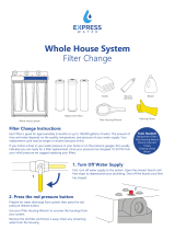
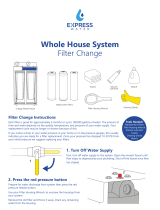
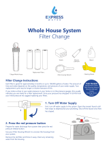
Leaks…Between cap and bottom of housing:
1. Turn off water supply and press the red pressure-relief button.
2. Clean and lubricate o-ring if necessary, then screw bottom of housing
onto cap and hand-tighten. DO NOT OVER-TIGHTEN.
4
Mfg. By Pentair Water Treatment ® 2003
145817 Rev B 10/03
WARRANTY
Pentek warrants to the original owner (under normal use): all products and parts to be free from defects in material and workmanship for a period of one (1) year. Notwithstanding the foregoing, (a) the warranty period for sumps shall be a period of five (5) years. Any
replacement products furnished will be free from defects in material and/or workmanship for the remainder of the original warranty period, or 30 days, whichever is longer. This warranty does not cover: (1) cartridges, media, and accessories (2) defects not reported
within the above time period, (3) items manufactured by other companies, (4) problems arising from failure to comply with Pentek instructions, (5) problems and/or damage arising from acts of nature, abuse, misuse, negligence or accident by any party other than Pentek,
(6) problems and/or damage resulting in whole or in part from alteration, modification, repair or attempted alteration, modification or repair by any party other than Pentek, (7) noncompliance with applicable codes/ordinances. If a defect in workmanship and/or material
in a product or part covered by the warranty should arise, Pentek, at its sole discretion, will repair or replace the defective product or part (Pentek may consider, in good faith, the customer's preference).
All claimed defective product must: (1) be authorized for return by Pentek with an RGA number (2) include proof of the purchase date of the product or part (3) returned to Pentek prior to the expiration of the warranty date, at the customer's expense, shipment pre-paid,
(4) be accompanied by a letter detailing the Model Number, Serial Number (if any), and a brief description of the problem. TO THE MAXIMUM EXTENT PERMITTED BY APPLICABLE LAW, PENTEK DISCLAIMS ALL OTHER WARRANTIES, WHETHER EXPRESS OR IMPLIED,
INCLUDING, BUT NOT LIMITED TO, THE IMPLIED WARRANTY OF MERCHANTABILITY AND FITNESS FOR A PARTICULAR PURPOSE, WITH REGARD TO THE PRODUCTS, PARTS AND ANY ACCOMPANYING WRITTEN MATERIALS.
To the maximum extent permitted by applicable law, Pentek shall not be liable for any damages whatsoever (including, but not limited to, loss of time, inconvenience, expenses, labor or material charges incurred in connection with the removal or replacement of the
products or parts, special, incidental, consequential, or indirect damages for personal injury, loss of business profits, business interruption, loss of business information, or any other pecuniary loss) arising out of the use of or inability to use the defective products or parts,
even if Pentek has been advised of the possibility of such damages. Penteks' maximum liability under any provision of this Limited Warranty shall be limited to the amount actually paid for the products or parts. NOTE: Because some states do not allow the exclusion or
limitation of incidental or consequential damages, the above limitations or exclusions may not apply. THIS WARRANTY GRANTS SPECIFIC LEGAL RIGHTS, AND OTHER RIGHTS MAY APPLY. SUCH RIGHTS VARY FROM STATE TO STATE.
PENTEK FILTRATION
502 Indiana Avenue • Sheboygan, WI 53081
Toll Free Technical Support: 800-861-8758 • Technical Support: 920-451-9301 • [email protected]
Phone 920-457-9435 • www.pentekfiltration.com
International Fax: 920-457-2417 • [email protected]
Chlorine
Bad Taste Sediment
Taste & Odor
C1 5 micron nom. Carbon-impregnated 5 gpm/2 psi 3 mo.
Cellulose
CC-10 Granular Activated Carbon 1 gpm/3 psi 6 mo.
(coconut-shell)
GAC-10 Granular Activated Carbon 1 gpm/3 psi 6 mo.
CBC
®
-10 .5 micron nom. Activated Carbon Block 1 gpm/< 2 psi 12 mo.
Scale and Coarse Sand, dirt, Fine sand, Extra-fine sand,
Rust particles sand silt dirt, silt dirt, silt
CP5-BB 5 micron nom. Pleated Cellulose /Polyester 20 gpm/< 1 psi 3 mo.
••
S1-BB 20 micron nom. Pleated Cellulose 20 gpm/< 1 psi 4 mo.
••
R30-BB 30 micron nom. Pleated Polyester 25 gpm/< 1 psi 6 mo.
••
R50-BB 50 micron nom. Pleated Polyester 25 gpm/< 1 psi 6 mo.
••
Chlorine Bad Taste Sediment
Taste & Odor & Odor
RFC-BB 25 micron nom. Granular Activated Carbon 10 gpm/1 psi 3 mo. ••
On unit inlet/outlet connections:
1. Turn off water supply. Tighten compression fittings with a wrench.
DO NOT OVERTIGHTEN.
2.
Turn on water supply. If leaks persist, or if there are other leaks on unit, turn off
water supply.
Call Pentek Technical Support at 1-800-861-8758.
Replacement Filter Cartridges
WHOLE HOUSE Sediment Cartridges
UNDERSINK DRINKING Water Cartridges
HEAVY-DUTY Cartridges
Model Filtration Filter Material / Max Flow Rate/ Filter
Rating Construction Pressure Drop Life*
Model Filtration Filter Material / Max Flow Rate/ Filter
Rating Construction Pressure Drop Life*
Model Filtration Filter Material / Max Flow Rate/ Filter
Rating Construction Pressure Drop Life*
Reduces:
Reduces:
Reduces:
* Filter life depends on usage
and water conditions.
  • Page 1 1
  • Page 2 2
  • Page 3 3
  • Page 4 4

Pentek PENTEK-150166 User manual

Category
Sanitary ware
Type
User manual

Ask a question and I''ll find the answer in the document

Finding information in a document is now easier with AI