Infinity Bass Link User manual

Category
Car audio amplifiers
Type
User manual

This manual is also suitable for

Models:
BassLink
BassLink
(Remote Level Control Ready)
BassLink X
Powered Automotive Subwoofer
SERVICE MANUAL
Infinity Systems, Inc.
250 Crossways Park Dr.
Woodbury, New York 11797
Rev 2 7/2003
Contents
ALL MODELS BASSLINK
SPECIFICATIONS …………………………………………..……………2
CONNECTIONS/APPLICATIONS ………………………………………3
TUNING BASSLINK…………………………………………………….…6
TROUBLESHOOTING ……………………………………………………7
TEST SETUP PROCEDURE ……………..………..……………………8
BASSLINK (Original version without Remote Level Control jack)
SERVICE BULLETIN INF2000-03 ………………………………………10
EXPLODED VIEW …………………………………………….…..………11
MECHANICAL PARTS LIST ……………….………………………….…12
BLOCK DIAGRAM …………..……………..………….………………….13
PCB DRAWINGS …………………………….……………………………14
ELECTRICAL PARTS LIST ………………………………………………24
SCHEMATICS …………………………………………………………..…29
PACKAGING …………………………………………………………….…31
BASSLINK or BASSLINK X (Versions with Remote Level Control jack)
SERVICE BULLETIN INF2003-01 ………………………………………33
EXPLODED VIEW ………………………….…………………..…………34
MECHANICAL PARTS LIST …………….….……………………………35
BLOCK DIAGRAM ………………………..………….…………………...36
PCB DRAWINGS …………………………….……………………………37
ELECTRICAL PARTS LIST ………………………………………………44
SCHEMATICS …………………………………………………………..…50
PACKAGING …………………………………………………………….…54
ALL MODELS BASSLINK
INTEGRATED CIRCUIT DIAGRAMS ………………………..…………55
1
Basslink/Basslink X
Specifications
BASSLINK/BASSLINK w/ Remote Level Control/BASSLINK X
Amplifier Power: 200W RMS @10% THD
120W RMS @1% THD
Frequency Response: 20Hz – 120Hz
THD @ 30W 1.0%
Input Sensitivity: 50mV – 4V Line-Level Input
1V – 16V Universal Interface
Maximum Input Sensitivity 7mV Line-Level Input
(Gain level @ Max) 120mV Universal Interface
Crossover Frequency: 50Hz – 120Hz
Crossover Slope: 12dB/octave
Bass Boost: –6 to +3 dB @ 40Hz
Signal-Noise Ratio 65dB (Wide band w/ 22K LPF)
Max Gain Level Noise 3.0 mV Basslink
(Level pot Max.) 1.8 mV Basslink w/ Remote Level Control
1.8 mV Basslink X
Max Gain Level Noise 2.0 mV Basslink
(Level pot Min.) 1.7 mV Basslink w/ Remote Level Control
1.7 mV Basslink X
Auto On/Off Time From 1 1/2 to 5 min.
(depending on last input signal level)
Gain boost (min to max) 9.0 dB
Fuse: 25A Basslink
20A Basslink w/ Remote Level Control
20A Basslink X
Maximum Current Draw: 12A
Quiescent Current Draw: <800 mA
Protection Circuits:
Over/Under voltage 17.5, 8.5 VDC
Temperature 95° C
Short Circuit w/ 0.1 W resistor
DC Offset Yes
Dimensions: 14-1/2" x 12-1/2" x 8-1/2" (L x W x H)
(369mm x 318mm x 216mm)
Weight 16 lbs./7.2kg
Infinity continually strives to update and improve existing products, as well as create new ones. The specifications and
construction details in this and related Infinity publications are therefore subject to change without notice.
2
3
Connect power to BassLink, as shown in Figure 5.
Also observe these installation tips:
Use at least #12 AWG wire for the +BATT
(+12 Vdc) and GND (ground) connections. If
needed, use at least a #20 AWG wire for the
REM (remote) connection.
Route all power wires through a grommet in
the vehicles firewall. If a factory grommet is
unavailable, install one.
Connect a short GND wire from BassLink to the
nearest bare metal surface. For a good connec-
tion, scrape away paint from the metal surface
and use a screw with a lock (star) washer.
Figure 5. Power connections for BassLink.
Install a fuse holder with a 20 A fuse within 18"
of the battery + terminal (see Figure 5).
The REM connection requires +5 to +12 Vdc
signal for BassLink to turn on remotely. Most
head units with preamp outputs provide this
remote voltage signal. For speaker-level appli-
cations, a remote connection is not required,
since BassLinks Auto Turn-On feature will
sense voltage on the speaker wires to
automatically turn on BassLink.
IMPORTANT:To enable BassLinks Auto
Turn-On feature, set AUTO TURN-ON to the
AUTO position (see Figure 12 on page 6).
POWER CONNECTIONS
BassLink is equipped with four line-level (RCA)
inputs and four speaker-level inputs. Any combina-
tion of line-level and speaker-level inputs may be
used to provide nonfading bass when connected to
a head unit with four outputs.
Figure 6. BassLink audio connections for a head
unit with two line-level or subwoofer (RCA) outputs.
To help you plan your installation, we included
five system applications in Figures 6 through 10
on pages 3 through 5. For more system ideas, see
your authorized Infinity car-audio dealer.
Note: The applications show the optional remote
SUB LEVEL control which installs under the dash-
board for easy in-car bass level adjustments.
APPLICATIONS
Chassis Ground
(Bare Metal)
BassLink
(right side panel)
Remote
Turn-On
Fuse 20 A
Source Unit
18"
Battery
LF Speaker
+
RF Speaker
LR Speaker
Subwoofer or
Line-Level
Outputs
(on Source Unit)
Sub Level
Control
(optional)
RL
RR Speaker
+
++
Source Unit
BassLink
(right side)
Sub Level Control
(optional)
+
RCA Stereo Cables
(not supplied)
Note: For the original version Basslink without the AUTO OFF/ON switch and Optional Sub
Level Control, references to these items in the Connections, Applications and Controls sections
can be ignored - all other information is valid.
4
Figure 7. BassLink audio connections for a head
unit equipped with four line-level (RCA) outputs.
APPLICATIONS (CONTINUED)
Figure 8. BassLink audio connections for a head
unit equipped with two line-level (RCA) outputs
and two speaker-level outputs.
LF Speaker
+
RF Speaker
LR Speaker
Line-Level Outputs
(on Source Unit)
Sub Level
Control
(optional)
RFLRRR LF
RR Speaker
+
++
Source Unit
BassLink
(right side)
Sub Level Control
(optional)
+
RCA Stereo Cables
(not supplied)
LF Speaker
+
RF Speaker
LR Speaker
Line-Level
Outputs
(on Source Unit)
Sub Level
Control
(optional)
RF LF
Speaker Wires
(spliced)
RR LR
RR Speaker
+
++
Source Unit
BassLink
(right side)
Sub Level Control
(optional)
VIOLET GREEN/BLACK
VIOLET/BLACK GREEN
+
RCA Stereo Cables
(not supplied)
Splices
(not supplied)
Splices
(not supplied)
6
BassLink provides several controls and indicators
that simplify sonic integration with virtually any
vehicles unique acoustic properties. They are
located on the front and side panels, as shown in
Figures 11 and 12.
Figure 11. BassLink controls on the front panel.
POWER LED:This indicator will glow red when
BassLink is operational.
GAIN Control: Use this control to adjust the rela-
tive volume (loudness) of BassLink with respect
to the other speakers in the vehicle.
CROSSOVER: Use this control to adjust the
amount of high-frequency information present in
BassLinks output. A lower value signifies less
high frequencies will be amplified.
BASS BOOST: Use this control to correct any
perceived peak or dip in the bass response
(typically around 40Hz in most vehicles). Set the
control to any value between 6dB and +3dB,
according to what sounds best.
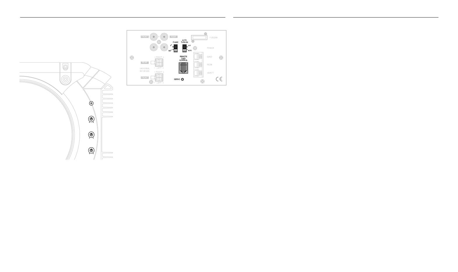
Figure 12. BassLink controls on right side panel.
PHASE Control: Use this switch to reverse the
phase of BassLinks output with respect to its
input. Choose the position (0° or 180°) that
sounds the best.
Note: Depending on BassLinks orientation and
location in a vehicle, reversing the phase may
may (or may not) increase or decrease the
amount of upper bass being reproduced.
AUTO TURN-ON: For speaker-level connections,
use this switch to activate (or deactivate) BassLinks
automatic turn-on circuit. For most speaker-level
applications, slide the switch to AUTO. However, if
your system produces false turn-on signals or uses
a remote (REM) connection, slide the switch to OFF.
REMOTE GAIN CONTROL: Use this RJ-11 jack to
connect the optional remote SUB LEVEL control.
SERVO LED:This indicator glows green when the
subwoofer is at maximum excursion and the
amplifier is modifying the output to maintain
maximum performance. Be sure to monitor this
indicator during BassLink setup (see Tuning
BassLink). When properly tuned, the SERVO LED
should light momentarily during high-level bass
transients. Avoid adjustments that cause the LED
to remain lit for extended periods.
CONTROLS AND FUNCTIONS
1. Make sure the head unit is off and its volume
control is set to minimum.
2. On BassLinks front panel, initially set all con-
trols to their midpoint positions, as shown in
Figure 11. On BassLinks side panel, initially set
PHASE to 0° and AUTO TURN-ON to AUTO, as
shown in FIgure 12.
3. Turn on the head unit and play a favorite music
track that has substantial bass. Set the volume
control to 75 percent of the total output
(approximately 3 oclock on rotary controls).
4. Adjust the GAIN control clockwise until the
SERVO LED (on BassLinks side panel) begins
to flash with each bass note but doesnt stay
lit continuously.
5. Listen to your system, making a mental note
of the amount of upper bass being reproduced.
6. Switch the PHASE control to 180° and listen
again for upper bass content. There may be
more upper bass, less upper bass, or no
change at all. The position that provides the
most upper bass is correct, but choose either
setting according to your taste.
7. Adjust the CROSSOVER control clockwise or
counterclockwise until you hear only low-fre-
quency information. For example, you should
NOT hear any vocals coming from BassLink
when seated in the normal listening position.
8. Adjust the BASS-BOOST control clockwise or
counterclockwise to suit your taste.
9. Recheck the SERVO LED to make sure its
flashing in time with the bass but is not lit
continuously. If it is lit continuously, adjust the
GAIN control counterclockwise until the
SERVO LED only flashes.
Note: In most cases, the above steps will provide
satisfactory tuning. However, the actual process
may require several readjustments of each control,
since the settings will interact with each other.
If necessary, consult your authorized Infinity
car audio dealer for help in tuning your system.
TUNING BASSLINK
Power
Gain
Min Max
50 Hz
Crossover
120 Hz
Bass Boost
-6 (dB) +3
(Blue on Basslink X)
Basslink/Basslink X
TROUBLESHOOTING
• PROBLEM:
POWER LED not lit.
CAUSES and SOLUTIONS:
1. Fuse is blown and needs replacement.
2. Head unit not functioning properly. Check
remote voltage, and power, ground or
remote connections.
• PROBLEM:
POWER LED is lit but there is no bass.
CAUSES and SOLUTIONS:
1. Inputs are not connected. Check connections.
2. Head-unit fader control is not set properly.
Adjust head-unit fader control to feed audio
signals to BassLink.
• PROBLEM:
BassLink sounds muddy or distorted.
CAUSES and SOLUTIONS:
1. Gain is set too high and SERVO LED is lit
constantly. Readjust GAIN control (see
Tuning BassLink on the previous page).
2. Bass is set too high. Readjust BASS BOOST
control (see Tuning BassLink on the previous
page).
3. Head-unit output is distorted or blown. See
your authorized Infinity car audio dealer.
• PROBLEM:
No output from BassLink when head-unit
fader control set to front or rear (in a 4-channel
connection).
CAUSE and SOLUTION:
Input connections are improperly wired. Verify all
connections (see Applications section)
APPLICABLE TO BASSLINK WITH LEVEL
CONTROL JACK AND BASSLINK X ONLY:
• PROBLEM:
BassLink turns on before head unit is completely on
and produces a “thump” sound.
CAUSE and SOLUTION:
For speaker-level connections, head unit is
producing a false turn-on signal. On BassLink’s
side panel, slide AUTO TURN-ON to OFF.
• PROBLEM:
BassLink’s POWER LED remains on after head
unit is turned off.
CAUSE and SOLUTION:
For speaker-level connections, this is normal
operation when AUTO TURN-ON is set to ON.
BassLink will remain on another 5 to 10 minutes
after sensing that audio signals are not present
before shutting down. If you prefer immediate shut-
down, set AUTO TURN-OFF to OFF.
7
BassLink/BassLink X
8
Equipment needed:
Function/signal generator/sweep generator
Integrated/Power Amplifier (capable of driving 2 ohm loads)
14 volt DC power supply 20A or greater with current-limit protection
Multimeter
RCA cable, Universal Interface molex connector, Speaker cables
General Unit Function (UUT = Unit Under Test)
Switch/Controls:
GAIN control full counterclockwise (Min)
CROSSOVER full clockwise (120 Hz)
BASS BOOST at center (12 o’clock)
PHASE, AUTO-ON - either position
1) From the signal generator, connect one line level (RCA) cable to the Basslink Line Level Input jacks (Front,L/R) on the UUT. Use
a Y-cable from a mono source if necessary to connect to both inputs.
2) Turn on generator, adjust to 100mV, 40 Hz.
3) Attach 14v DC source to Power terminals on UUT, including +14v to Remote connection. Red LED should ON. Turn LEVEL con-
trol full clockwise (Max)
4) Bass response should be heard and felt. Green servo light should not be illuminated.
5) Adjust the generator to 175mV, 40 Hz. Green servo light should turn ON. DO NOT DRIVE THE BASSLINK FOR MORE THAN A
FEW SECONDS AT THIS LEVEL OR THE UUT MAY GO INTO THERMAL PROTECTION
6) Turn off generator, turn GAIN control fully counterclockwise, disconnect RCA cable.
7) Optional: Attach the Universal Interface molex connector (Infinity part# 162A600D001) to the Basslink Universal Interface Jack
(Front,L/R) on the UUT. Both front/rear negative wires should be twisted and connected together; positive wires should be treated
likewise. Cables should be connected to an integrated amplifier fed by the signal generator.
8) Turn on generator and adjust so that speaker level input at the amplifier is 275mV, 40 Hz. Turn GAIN control full clockwise.
9) Bass response should be heard and felt. Green servo light should not be illuminated.
10) Adjust the generator to 500mV, 40 Hz. Green servo light should be ON. DO NOT DRIVE THE BASSLINK FOR MORE THAN A
FEW SECONDS AT THIS LEVEL OR THE UUT MAY GO INTO THERMAL PROTECTION
Sweep Function
1) Follow steps 1-3 above, using a sweep generator as a signal source – adjust the generator to 50mV, 40 Hz.
2) Sweep generator from 20Hz to 300Hz. Listen for any rattles, clicks, buzzes or any other noises. If any unusual noises are heard,
test woofer according to the instructions below.
Driver Function
1) Remove amplifier from the enclosure; (instructions in bulletin INF2000-03 page 8); detach connector M101 two-wire molex on the
main amplifier PCB.
2) Check DC resistance of woofer; it should be 2.3 ohms ±10%
3) Connect a pair of speaker cables to woofer terminals. Cables should be connected to an integrated amplifier fed by a signal gen-
erator. Turn on generator and adjust so that speaker level output is 6.0V.
4) Sweep generator from 20Hz to 1kHz. Listen to driver for any rubbing, buzzing, or other unusual noises.
SIGNAL
GENERATOR
AMPLIFIER
AC VOLT
METER (10V)
BASSLINK
UNDER TEST
00432
-
+
14V DC
Test Set Up Procedure
Basslink
(Original version without remote
level control jack)
9
Infinity Systems Inc. 250 Crossways Park Dr. Woodbury, New York 11797 (516) 496-3400
Service Bulletin
Service Bulletin INF2000-03 - October 2000 Warranty labor rate: MINOR repair
To: All Infinity Service Centers
Model: Basslink (version w/o AUTO-ON switch or REMOTE GAIN)
Subject: Unit will not turn off
In the event you receive a Basslink subwoofer with the complaint: “The unit will not turn off, even when
the audio signal is removed, and the Remote power connection is switched off” (indicated by the
Basslink’s red LED remaining ON), perform the following modification:
1) Set the unit on a padded surface and remove all external cables.
2) On the amplifier faceplate, remove only the (14) Phillips mounting screws as shown in Figure 1.
3) Remove the amplifier assembly from the enclosure. If the amp is turned around and supported correctly,
no other connectors need to be unplugged.
4) Add these two components:
1.0 Meg ohm 1/8W resistor, Infinity part# 299-1M
.01uf, 100v mylar capacitor, Infinity part# 140-PF2A103F
Solder these parts in parallel (See Figure 2); and attach to original location shown (See Figure 3), which is in
a narrow cavity between main power supply caps and transformer T101. There are two empty pads on the
PCB for these parts with marked designators R272 and C273.
5) New gaskets must be added to the amplifier mating surface; two pairs are required, four gaskets total:
Infinity part# 723D150 and #723C150
6) Replace the amplifier assembly and tighten all mounting screws. Use caution; a hand tool is
recommended to prevent stripping the threads in the enclosure.
7) Connect +12v to the unit and a signal cable, after the unit cycles ON, (red LED should be lit), remove the
signal and remote connection only (or shut off the music source if using the Universal Interface). Unit
should turn OFF after 3 - 10 minutes (as indicated by the red LED turning OFF).
Models Serial number Status Action
Basslink
All serial numbers affected
(version w/o AUTO-ON
switch or REMOTE GAIN)
The unit will not turn off when the
signal is removed, and Remote
connection is switched off
Add:
R272 1 Meg ohm 1/8W Resistor
C273 .01uf 100v Mylar Capacitor
New amplifier gaskets #723D150, 723C150
10
BassLink
11
Exploded View
J
M
1
2
L
K
3
4
5
12
8
11
13
9
8
29
28
6
7
8
12
J
H
G
F
E
D
28
7
13
9
35
29
G
H
I
F
E
K
31
6
16
25
24
42
32
27
K
26
17
25
11
43
15
H
22
23
19
20
18
J
I
6
19
15
44
2
30
9
10
21
9
14
C
B
A
1
2
3
4
5
6
7
8
12
9
10
11
4
13
14
15
39
39
M
16
L
1
K
38
34
D
15
B
15
39
14
36
5
3
37
40
F
E
37
G
D
38
40
41
C
40
B
A
36
39
J
H
G
F
E
D
12
40
12
1
C
A
36
36
33
12
9
10
11
13
14
15
C
B
A
16
NOTE: THIS DRAWING AND MECHANICAL PARTS
LIST ARE FOR REFERENCE PURPOSES ONLY;
THE MAIN ENCLOSURE OF THE BASSLINK
SUBWOOFER, WITH THE EXCEPTION OF THE
AMPLIFIER ASSEMBLY, IS
NON-SERVICABLE.
COMPLETE ENCLOSURE W/ DRIVERS
PART# BASSLINK/ASSEMBLY
00425
BassLink
12
Mechanical Parts List
42 NLA-REPAIR MAIN ASS'Y PCB
1
43 1010DS150-1 AMP-SMD ASS'Y
1
44 NLA-REPAIR TONE CONTROL PCB ASS'Y
1
BassLink
13
Block Diagram
BassLink
14
Main PCB
BassLink
15
Main PCB (Cont.)
BassLink
16
Main PCB (Cont.)
BassLink
17
Main PCB (Cont.)
BassLink
18
Main PCB (Cont.)
BassLink
19
Main PCB (Cont.)
  • Page 1 1
  • Page 2 2
  • Page 3 3
  • Page 4 4
  • Page 5 5
  • Page 6 6
  • Page 7 7
  • Page 8 8
  • Page 9 9
  • Page 10 10
  • Page 11 11
  • Page 12 12
  • Page 13 13
  • Page 14 14
  • Page 15 15
  • Page 16 16
  • Page 17 17
  • Page 18 18
  • Page 19 19
  • Page 20 20
  • Page 21 21
  • Page 22 22
  • Page 23 23
  • Page 24 24
  • Page 25 25
  • Page 26 26
  • Page 27 27
  • Page 28 28
  • Page 29 29
  • Page 30 30
  • Page 31 31
  • Page 32 32
  • Page 33 33
  • Page 34 34
  • Page 35 35
  • Page 36 36
  • Page 37 37
  • Page 38 38
  • Page 39 39
  • Page 40 40
  • Page 41 41
  • Page 42 42
  • Page 43 43
  • Page 44 44
  • Page 45 45
  • Page 46 46
  • Page 47 47
  • Page 48 48
  • Page 49 49
  • Page 50 50
  • Page 51 51
  • Page 52 52
  • Page 53 53
  • Page 54 54
  • Page 55 55
  • Page 56 56

Infinity Bass Link User manual

Category
Car audio amplifiers
Type
User manual
This manual is also suitable for

Ask a question and I''ll find the answer in the document

Finding information in a document is now easier with AI