
CSM 14
CSM 28
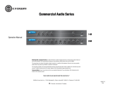
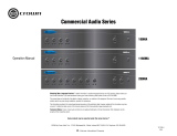
Commercial Series Mixer
Operation Manual
JBL Commercial Series

2
This manual does not include all of the details of design, production, or variation of the equipment. Nor does it
cover every possible situation which may arise during installation, operation or maintenance.
The information provided in this manual was deemed accurate as of the publication date. However, updates to
this information may have occured.
Trademark Notice: JBL is registered trademark of JBL International. CROWN and DRIVECORE are registered
trademarks of Crown Audio. Other trademarks are the property of their respective owners.
© 2014 JBL Commercial, 8760 South Sandy Parkway, Sandy, UT. All Rights Reserved.
Contents
Important Safety Instructions .......................................................................... 3
JBL DECLARATION OF CONFORMITY .......................................................... 5
1.0 Welcome ................................................................................................... 7
1.1 Features ................................................................................................. 7
1.2 Front Control Panels and Indicators ...................................................... 8
1.3 Rear Panel Controls and Connectors - Four Channel............................ 9
1.4 Rear Panel Controls and Connectors - Eight Channel............................10
2.0 Setup ........................................................................................................12
2.1 Unpacking Your Unit ..............................................................................12
2.2 Installing Your Unit .................................................................................12
2.3 Choosing Wire and Connectors .............................................................17
2.4 Wiring Your Audio System .....................................................................18
2.5 Connecting to AC Mains .....................................................................19
2.6 Startup Procedure .................................................................................19
3.0 Operation ..................................................................................................20
3.1 Precautions ............................................................................................20
3.2 Input Routing .........................................................................................21
3.3 Phantom Power ......................................................................................21
3.4 VOX Ducking .........................................................................................21
3.5 Priority Muting ........................................................................................21
3.6 Remote Volume Control .........................................................................21
4.0 Troubleshooting ........................................................................................22
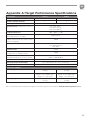
Appendix A: Target Performance Specifications ............................................23
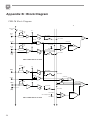
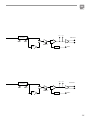
Appendix B: Block Diagram ...........................................................................24
Appendix C: Contact Information ...................................................................26

3
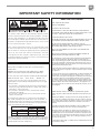
IMPORTANT SAFETY INFORMATION
WARNING FOR YOUR PROTECTION
READ THE FOLLOWING:
KEEP THESE INSTRUCTIONS
HEED ALL WARNINGS
FOLLOW ALL INSTRUCTIONS
THE APPARATUS SHALL NOT BE EXPOSED TO DRIPPING OR
SPLASHING LIQUID AND NO OBJECT FILLED WITH LIQUID, SUCH
AS VASES, SHALL BE PLACED ON THE APPARATUS
CLEAN ONLY WITH A DRY CLOTH.
DO NOT BLOCK ANY OF THE VENTILATION OPENINGS. INSTALL IN
ACCORDANCE WITH THE MANUFACTURER’S INSTRUCTIONS.
DO NOT INSTALL NEAR ANY HEAT SOURCES SUCH AS
RADIATORS, HEAT REGISTERS, STOVES, OR OTHER APPARATUS
(INCLUDING AMPLIFIERS) THAT PRODUCE HEAT.
ONLY USE ATTACHMENTS/ACCESSORIES SPECIFIED BY THE
MANUFACTURER.
UNPLUG THIS APPARATUS DURING LIGHTNING STORMS OR
WHEN UNUSED FOR LONG PERIODS OF TIME.
Do not defeat the safety purpose of the polarized or grounding-type
plug. A polarized plug has two blades with one wider than the
other. A grounding type plug has two blades and a third grounding
prong. The wide blade or third prong are provided for your safety. If
the provided plug does not fit your outlet, consult an electrician for
replacement of the obsolete outlet.
Protect the power cord from being walked on or pinched particularly
at plugs, convenience receptacles, and the point where they exit from
the apparatus.
Use only with the cart stand, tripod bracket, or table specified by the
manufacture, or sold with the apparatus. When a cart is used, use
caution when moving the cart/apparatus combination to avoid injury
from tip-over. Refer all servicing to to qualified service personnel.
Servicing is required when the apparatus has been damaged in any
way, such as power-supply cord or plug is damaged, liquid has been
spilled or objects have fallen into the apparatus, the apparatus has
been exposed to rain or moisture, does not operate normally, or has
been dropped.
POWER ON/OFF SWITCH: For products provided with a power
switch, the power switch DOES NOT break the connection from the
mains.
MAINS DISCONNECT: The plug shall remain readily operable. For
rack-mount or installation where plug is not accessible, an all-pole
mains switch with a contact separation of at least 3 mm in each pole
shall be incorporated into the electrical installation of the rack or
building.
FOR UNITS EQUIPPED WITH EXTERNALLY ACCESSIBLE FUSE
RECEPTACLE: Replace fuse with same type and rating only.
MULTIPLE-INPUT VOLTAGE: This equipment may require the use
of a different line cord, attachment plug, or both, depending on the
available power source at installation. Connect this equipment only
to the power source indicated on the equipment rear panel. To reduce
the risk of fire or electric shock, refer servicing to qualified service
personnel or equivalent.
If connected to 240V supply, a suitable CSA/UL certified power cord shall
be used for this supply.
SAFETY INSTRUCTIONS
NOTICE FOR CUSTOMERS IF YOUR UNIT IS EQUIPPED WITH A
POWER CORD.
WARNING: THIS APPLIANCE SHALL BE CONNECTED TO A MAINS
SOCKET OUTLET WITH A PROTECTIVE EARTHING CONNECTION.
The cores in the mains lead are coloured in accordance with the following code:
GREEN and YELLOW - Earth BLUE - Neutral BROWN - Live
As colours of the cores in the mains lead of this appliance may not cor-
respond with the coloured markings identifying the terminals in your plug,
proceed as follows:
•
The core which is coloured green and yellow must be connected to the
terminal in the plug marked with the letter E, or with the earth symbol, or
coloured green, or green and yellow.
•
The core which is coloured blue must be connected to the terminal
marked N or coloured black.
•
The core which is coloured brown must be connected to the terminal
marked L or coloured red.
This equipment may require the use of a different line cord, attachment
plug, or both, depending on the available power source at installation. If
the attachment plug needs to be changed, refer servicing to qualified ser-
vice personnel who should refer to the table below. The green/yellow wire
shall be connected directly to the units chassis.
CONDUCTOR
WIRE COLOUR
Normal Alt
L LIVE BROWN BLACK
N NEUTRAL BLUE WHITE
E EARTH GND GREEN/YEL GREEN
WARNING: If the ground is defeated, certain fault conditions in the unit or
in the system to which it is connected can result in full line voltage between
chassis and earth ground. Severe injury or death can then result if the chassis
and earth ground are touched simultaneously.
The symbols shown above are internationally accepted symbols
that warn of potential hazards with electrical products. The light-
ning flash with arrowpoint in an equilateral triangle means that
there are dangerous voltages present within the unit. The exclama-
tion point in an equilateral triangle indicates that it is necessary for
the user to refer to the owner’s manual.
These symbols warn that there are no user serviceable parts inside
the unit. Do not open the unit. Do not attempt to service the unit
yourself. Refer all servicing to qualified personnel. Opening the
chassis for any reason will void the manufacturer’s warranty.
Do not get the unit wet. If liquid is spilled on the unit, shut it off
immediately and take it to a dealer for service. Disconnect the unit
during storms to prevent damage.

4
IMPORTANT SAFETY INFORMATION
ELECTROMAGNETIC
COMPATIBILITY
This device complies with part 15 of the FCC Rules and the
Product specifications noted on the Declaration of Conformity.
Operation is subject to the following two conditions:
•
this device may not cause harmful
interference, and
•
this device must accept any interference received, including
interference that may cause undesired operation.
Operation of this unit within significant
electromagnetic fields should be avoided.
•
use only shielded interconnecting cables.
U.K. MAINS PLUG WARNING
A molded mains plug that has been cut off from the cord is
unsafe. Discard the mains plug at a suitable disposal facility.
NEVER UNDER ANY CIRCUMSTANCES SHOULD YOU INSERT
A DAMAGED OR CUT MAINS PLUG INTO A 13 AMP POWER
SOCKET. Do not use the mains plug without the fuse cover in
place. Replacement fuse covers can be obtained from your local
retailer. Replacement fuses are 13 amps and MUST be ASTA
approved to BS1362.
If you want to dispose this product, do not mix it with gen-
eral household waste. There is a separate collection system
for used electronic products in accordance with legislation
that requires proper treatment, recovery and recycling.
Private household in the 25 member states of the EU, in Switzerland
and Norway may return their used electronic products free of charge to
designated collection facilities or to a retailer (if you purchase a similar
new one).
For Countries not mentioned above, please contact your local authorities
for a correct method of disposal.
By doing so you will ensure that your disposed product undergoes the
necessary treatment, recovery and recycling and thus prevent potential
negative effects on the environment and human health.
MAGNETIC FIELD
CAUTION! Do not locate sensitive high-gain equipment such as preamplifiers
or tape decks directly above or below the unit. Because this amplifier has a
high power density, it has a strong magnetic field which can induce hum into
unshielded devices that are located nearby. The field is strongest just above
and below the unit.
If an equipment rack is used, we recommend locating the amplifier(s) in
the bottom of the rack and the preamplifier or other sensitive equipment
at the top.

5
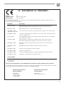
EC - DECLARATION OF CONFORMITY
Brand: JBL
Equipment Type: Commercial Audio Mixer
Model names: CSM 14, CSM 28
We, Harman International, declare under our sole responsibility that the product, to which this declaration relates, is in
conformity with the following standards.
Due to line current harmonics, we recommend that you contact your supply authority before connection.
We certify that the product identified above conforms to the requirements of the EMC Council Directive 89/336/EEC as amended
by 92/31/EEC, and the Low Voltage Directive 73/23/EEC as amended by 93/68/EEC.
Report No. Description
EN 55103-1:2009 EMC Compatibility – Product Family Standard for Audio, Video, Audio-Visual and
Entertainment Lighting Control Apparatus for Professional Use, Part 1: Emissions
EN 55103-1:2009 Magnetic Field Emissions – Annex A @ 10cm and 20cm
EN 61000-3-2:2005,
AMD1:2008, & A2:2009
Limits for Harmonic Current Emissions (equipment input current less than or equal to 16A
EN 61000-3-3:2008 Limitation of Voltage Fluctuations and Flicker in Low-Voltage Supply systems Rated Current
less than or equal to 16A
EN 55022:2010 Limits and Methods of Measurement of Radio Disturbance Characteristics of ITE: Radiated
& Conducted, Class B Limits
EN 55103-2:2009 EMC Compatibility – Product Family Standard for Audio, Video, Audio-Visual and
Entertainment Lighting Control Apparatus for Professional Use, Part 2: Immunity
EN 61000-4-2:2009 Electrostatic Discharge Immunity (Environment E2-Criteria B, 4k V Contact, 8k V Air
Discharge)
EN 61000-4-3:2010
Ed 3.2
Radiated, Radio-Frequency, EMC Immunity (Environment E2, Criteria A)
EN 61000-4-4:2007 Electrical Fast Transient/Burst Immunity (Criteria B)
EN 61000-4-5:2006 Surge Immunity (Criteria B)
EN 61000-4-6:2006 Immunity to Conducted Disturbances Induced by Radio-Frequency Fields (Criteria A)
EN 61000-4-11:2004 Voltage Dips, Short Interruptions and Voltage Variation
Safety Standard:
IEC 60065:2001 – 7th
Ed., AMD1:2005,
& AMD2:2010
Safety Requirements – Audio, Video, and Similar Electronic Apparatus
European Representative’s
Name and Address:
David Budge
10 Harvest Close
Yateley, GU46 6YS
United Kingdom
Responsible for the technical
documentation is:
Wilson Zhou

6

7
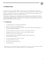
1.0 Welcome
The JBL
®
Commercial Series Mixers are professional tools designed and built for
Installed sound applications. There are both single channel and two channel models
with four or eight mixer channels, respectively. They provide mixer capability with
independent level control for each input channel.
The product includes a rack mounting kit for installations to a cabinet. The system
can be easily expanded with additional JBL Commercial Series Amplifiers and Com-
mercial Series Mixer-amplifiers. Provisions are included for a remote volume control
using the JBL CSR-V control module.
1.1 Features
• 4 or 8 inputs with 1 or 2 outputs, respectively
• Ideal for commercial and industrial use
• System may be expanded by adding JBL Commercial Series Mixer-amplifiers or
Commercial Series Amplifiers.
• Euro-block type mic/line input connectors and output connectors
• Independent Bass and Treble controls for each output channel
• VOX ducking during announcements
• Remote volume control capability using JBL CSR-V module and
standard ethernet cable
• Priority muting using PTT switch closure
• Configurable output routing
• Soft mute for quiet power on/off
• 3-Year Warranty*
*Warranty is only valid within the United States of America. For information on War-
ranty outside of the U.S.A., please contact your local distributor.

8
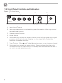
1.2 Front Panel Controls and Indicators
A. Input Level Controls
B. Input signal presence is indicated by green illumination of the ring around
the input level controls
C. Output Volume Controls
D. Power Switch
E. Illuminated ring around the output volume control will light green with signal
presence while red indicates clipping, i.e. the signal has reached the
threshold of audible distortion.
F. Tone Controls - Bass and Treble potentiometers on each output channel.
G. Illuminated ring around the power switch. Green indicates that the unit is
connected to the AC mains and is in standby. Blue indicates that the unit is
on and in normal operating mode.
Figure 1.2 Front View
A B C D
G
E
F
CSM 14
1 2 3 4

9
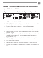
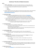
1.3 Rear Panel Controls and Connectors - Four Channel
A. AC Power Inlet – Detachable IEC
B. 70Hz HPF Switch - Activates this function to allow frequencies above 70Hz
pass through and reduce signals with lower frequency.
C. Phantom Power Switch - Applies 27V phantom power source for
microphones.
D. Mic/Line Selection Switch - Allows user to select the gain depending upon
the source used.
E. Dual RCA Input Connector - Stereo, unbalanced sources will be summed
together. (Ch2-4)
F. Priority Input Connector - 5-pin Euro-block includes 3 pins for a balanced
input as well as two pins that, when shortened together, activates the
priority function. (Ch1)
G. VOX Adjustment - allows the input level to be set that will invoke priority
override. (Ch1)
H. Line Level Output Connector
I. Remote Volume connector – RJ45 style connector to connect to a JBL
CSR-V control module.
J. Mic/Line Input Connector - 3-pin Euro-block connector, balanced input (Ch
2-4)
Figure 1.3 Rear View - CSM 14
100-240 V~ 50/60Hz 6W
MADE IN MALAYSIA
CAUTION - TO REDUCE THE RISK OF ELECTRIC
SHOCK, GROUNDING OF THE CENTER PIN OF
THE PLUG MUST BE MAINTAINED.
5040055
CSM 14
OUT
PHANTOM
70HZ
HPF
CSR-V ONLY
CH2 INPUT
MICLINE
CH1 INPUT
MICLINE
PRIORITY
VOX
CH3 INPUT
MICLINE
CH4 INPUT
MICLINE
MONO SUM MONO SUM
MONO SUM
A C D F GE
B
H I J

10
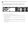
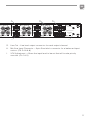
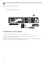
1.4 Rear Panel Controls and Connectors - Eight Channel
Figure 1.4 Rear View - CSM 28
A. AC Power Inlet – Detachable IEC
B. Dip switches for input routing and phantom power.
C. Mic/Line Selection Switch – Allows the user to select the gain depending
upon the source used.
D. Dual RCA Input Connector – Stereo, unbalanced sources will be summed
together. (Ch 2-8)
E. Priority Input Connector – 5-pin Euro-block includes 3 pins for a balanced
input as well as two pins that, when shorted together, activates the priority
function. (Ch 1 & 5)
F. Remote Volume Control – RJ45 style connector to connect to a JBL CSR-V
control module.
100-240 V~ 50/60Hz 10W
MADE IN MALAYSIA
CAUTION - TO REDUCE THE RISK OF ELECTRIC
SHOCK, GROUNDING OF THE CENTER PIN OF
THE PLUG MUST BE MAINTAINED.
5040054
CSM 28
CSR-V ONLY
21 3 4 5 6
7
8 9 10 11 12
MIC
MONO SUM
MONO SUM MONO SUM
1 2
OUT 1
CH4 INPUT
INPUT ROUTING
OUT 2
LINE
CH8 INPUT
CH3 INPUTCH7 INPUT
CH2 INPUTCH6 INPUT
CH1 INPUTCH5 INPUT
PRIORITY
PRIORITY
MICLINE
MICLINE
MICLINE
MICLINE
MICLINE
MICLINE
MICLINE
1 - CH1 TO OUT2
2 - CH2 TO OUT2
3 - CH3 TO OUT2
4 - CH4 TO OUT2
5 - OUT1 70HZ HPF
6 - PHANTOM
7 - CH5 TO OUT1
8 - CH6 TO OUT1
9 - CH7 TO OUT1
10 - CH8 TO OUT1
11 - OUT2 70HZ HPF
12 - NC
CH 1 VOX
CH 5 VOX
MONO SUM
MONO SUM
MONO SUM
C ED
A B
F G
H I

11
100-240 V~ 50/60Hz 10W
MADE IN MALAYSIA
CAUTION - TO REDUCE THE RISK OF ELECTRIC
SHOCK, GROUNDING OF THE CENTER PIN OF
THE PLUG MUST BE MAINTAINED.
5040054
CSM 28
CSR-V ONLY
21 3 4 5 6
7
8 9 10 11 12
MIC
MONO SUM
MONO SUM MONO SUM
1 2
OUT 1
CH4 INPUT
INPUT ROUTING
OUT 2
LINE
CH8 INPUT
CH3 INPUTCH7 INPUT
CH2 INPUTCH6 INPUT
CH1 INPUTCH5 INPUT
PRIORITY
PRIORITY
MICLINE
MICLINE
MICLINE
MICLINE
MICLINE
MICLINE
MICLINE
1 - CH1 TO OUT2
2 - CH2 TO OUT2
3 - CH3 TO OUT2
4 - CH4 TO OUT2
5 - OUT1 70HZ HPF
6 - PHANTOM
7 - CH5 TO OUT1
8 - CH6 TO OUT1
9 - CH7 TO OUT1
10 - CH8 TO OUT1
11 - OUT2 70HZ HPF
12 - NC
CH 1 VOX
CH 5 VOX
MONO SUM
MONO SUM
MONO SUM
C ED
A B
F G
H I
G. Line Out – Line level output connector for each output channel.
H. Mic/Line Input Connector – 3-pin Euro-block connector for a balanced input
source. (Ch 2-4 & 6-8)
I. VOX Adjustment – Allows the input level to be set that will invoke priority
override. (Ch 1 & 5)

12
2.0 Setup
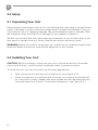
2.1 Unpacking Your Unit
Please unpack and inspect your unit for any damage that may have occurred during
transit. If damage is found, notify the transportation company immediately. Only you
can initiate a claim for shipping damage. We will be happy to help as needed. Save
the shipping carton as evidence of damage for the shipper’s inspection.
We also recommend that you save all packing materials so you will have them if you
ever need to transport the unit. Never ship the unit without the factory pack.
WARNING: Before you start to set up your unit, make sure you read and observe the
Important Safety Instructions found at the beginning of this manual.
2.2 Installing Your Unit
CAUTION: Before you begin, make sure your unit is disconnected from the power
source and all level controls turned completely down (counterclockwise).
To install the unit, you can use one of the following approaches:
• Rack mount the unit with the rack mounting kit, see Figure 2.2.2.
• Place a single unit on a surface with 12 inches of air space around the unit
for convection cooling. Rubber feet are included and can be attached onto
the underside of the chassis. For product dimensions, see Figure 2.2.1.

13
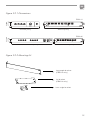
Figure 2.2.1 Dimensions
CSM 14
CSM 28
Figure 2.2.2 Mounting Kit
long angle bracket
(CSM 14 only)
flat bracket
(CSM 14 only)
front angle bracket
218.44 mm [8.6 in]
303.4 mm [11.9 in]
43.3 mm
[1.7 in]
436.88 mm [17.2 in] 303.4 mm [11.9 in]
43.3 mm
[1.7 in]

14
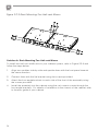
Solution A: Rack Mounting Two Half-rack Mixers
To install two half-rack width units in your cabinet system, refer to Figure 2.2.3 and
follow the steps below:
1. Align two modules side by side and upside down with the front panel towards
the same direction.
2. Connect them with the flat bracket using the screws provided.
3. Attach the front angle brackets to each side of the front of the assembly using
the screws provided.
4. Install the assembly into the cabinet using the rack mount screws through the
front angle brackets. For details of installation in the chassis of the cabinet, refer
to the user guide of your cabinet.
Figure 2.2.3 Rack Mounting Two Half-rack Mixers

15
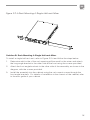
Figure 2.2.4 Rack Mounting A Single Half-rack Mixer
Solution B: Rack Mounting A Single Half-rack Mixer
To install a single half-rack unit, refer to Figure 2.2.4 and follow the steps below:
1. Determine which side of the rack opening will be used for the mixer and attach
the long angle bracket to the other side at the front using the screws provided.
2. Attach the front angle brackets to the other side of the assembly, as shown in the
diagram, with the screws provided.
3. Install the assembly into the cabinet using the rack mount screws through the
front angle brackets. For details of installation in the chassis of the cabinet, refer
to the user guide of your cabinet.

16
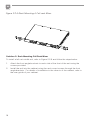
Solution C: Rack Mounting Full Rack Mixer
To install a full-rack width unit, refer to Figure 2.2.5 and follow the steps below:
1. Attach the front angle brackets to each side of the front of the unit using the
screws provided.
2. Install the unit into the cabinet using the rack mount screws through the front
angle brackets. For details of installation in the chassis of the cabinet, refer to
the user guide of your cabinet.
Figure 2.2.5 Rack Mounting A Full-rack Mixer

17
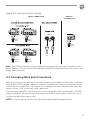
2.3 Choosing Wire and Connectors
We recommend using pre-built or professionally wired balanced line (two-conductor
plus shield) 22-24 gauge cables to connect the balanced input by using the includ-
ed Euroblock connectors, see Figure 2.3. Unbalanced lines may be used, but may
result in hum or RF noise very long cable runs.
You can also use RCA connectors to connect audio devices, for example, CD/DVD
player. However, do not use both Euroblock and RCA audio input connectors on a
single channel at the same time.
NOTE: Custom wiring should only be performed by qualified personnel.
MONO SUM
AUDIO
SOURCE
AUDIO
SOURCE
AUDIO
SOURCE
AUDIO
SOURCE
AUDIO
OUTPUT
OUTPUT
CONNECTOR
INPUT CONNECTOR
Figure 2.3 Input and Output Wiring
Note: Two RCA connectors are provided for summing left and right channels from a
stereo source. Do not use both Euroblock and RCA connectors concurrently for any
single input channel.

18
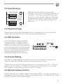
2.4 Wiring Your Audio System
Typical input and output wirings are shown in Figure 2.4.
INPUTS: Connect input wiring for both channels using either the RCA or the
Euroblock input for each channel.
OUTPUTS: The mixer’s line level output may be connected to the input of a power
amplifer such as a JBL Commercial Series Amplifer.
Figure 2.4 Wiring Audio System
Professional audio system
100-240 V~ 50/60Hz 6W
MADE IN MALAYSIA
CAUTION - TO REDUCE THE RISK OF ELECTRIC
SHOCK, GROUNDING OF THE CENTER PIN OF
THE PLUG MUST BE MAINTAINED.
5040055
CSM 14
OUT
PHANTOM
70HZ
HPF
CSR-V ONLY
CH2 INPUT
MICLINE
CH1 INPUT
MICLINE
PRIORITY
VOX
CH3 INPUT
MICLINE
CH4 INPUT
MICLINE
MONO SUM MONO SUM
MONO SUM
CD /OPTICAL
SPK 1 + 2 VIRTUAL
LEVEL
CSR-V

19
2.5 Connecting to AC Mains
Connect your mixer to the AC mains power source (power outlet) with the supplied
AC power cord. First, connect the IEC end of the cord set to the IEC connector on
the mixer; then, plug the other end of the cord set to the AC mains. When properly
connected to a live power source, the power ring should illuminate with a green
color.
WARNING: The third prong of this connector (ground) is an important safety
feature. Do not attempt to disable this ground connection by using an adapter or
other methods.
2.6 Startup Procedure
Use the following procedure when first turning on your system:
1. Turn down the level of your audio source.
2. Turn down the level controls of the amplifier.
3. Power up the mixer. The Power ring should change from green to blue.
4. Power up the amplifier that is connected to the mixer output.
5. Turn up the level of your audio source to an optimum level.
6. Turn up the level of your mixer to an optimum level.
7. Turn up the Level controls on the amplifier until the desired loudness or power
level is achieved.
If you ever need to make any wiring or installation changes, don’t forget to
disconnect the power cord.
Note: To avoid pop noises when powering down your system, it is recommended
that the amplifier used to drive the loudspeakers be turned off before the other
system components.

20
3.0 Operation
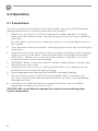
3.1 Precautions
Your unit is protected from internal and external faults, but you should still take the
following precautions for optimum performance and safety:
1. Before use, your unit first must be configured for proper operation, including
input and output wiring hookup. Improper wiring can result in serious operating
difficulties.
For information on wiring and configuration, please consult the Setup section of
this manual.
2. Use care when making connections, selecting signal sources and controlling the
output level.
3. Always be sure to have all levels at minimum when connecting or disconnecting
audio sources from the inputs, especially when MIC is selected from the MIC/
LINE switch. Failure to do so may cause the amplifier or speaker to go into a
protection mode or even cause damage.
4. WARNING: Never connect the output to a power supply, battery or power main.
Electrical shock may result.
5. Tampering with the circuitry, or making unauthorized circuit changes may be
hazardous and invalidates all agency listings.
6. Do not operate the unit with the red Clip LEDs constantly flashing.
7. Do not overdrive the unit, which will cause clipped signal to be sent to the
unit. Such signals will be reproduced with extreme accuracy, and loudspeaker
damage may result.
8. Use the unit in a well-ventilated environment and do not use it in ambient
temperature conditions in excess of 40°C.
CAUTION: JBL is not liable for damage that results from overdriving other
system components.
Page is loading ...
Page is loading ...
Page is loading ...
Page is loading ...
Page is loading ...
Page is loading ...
Page is loading ...
Page is loading ...
-
 1
1
-
 2
2
-
 3
3
-
 4
4
-
 5
5
-
 6
6
-
 7
7
-
 8
8
-
 9
9
-
 10
10
-
 11
11
-
 12
12
-
 13
13
-
 14
14
-
 15
15
-
 16
16
-
 17
17
-
 18
18
-
 19
19
-
 20
20
-
 21
21
-
 22
22
-
 23
23
-
 24
24
-
 25
25
-
 26
26
-
 27
27
-
 28
28


Crown 14M User manual
- Category
- Audio amplifiers
- Type
- User manual
Ask a question and I''ll find the answer in the document
Finding information in a document is now easier with AI
Related papers
-
 Crown Audio 28M User manual
-
Crown CT 8150 User manual
-
-
Crown Audio 180MA User manual
-
 Crown Audio 180MA User manual
-
-
Crown 160MA User manual
-
-
 Crown Audio 180MAx Pack User manual
-
 Crown Audio 180MAx Pack User manual


Other documents
-
TOA B-41S Specification Data
-
 orchardaudio Starkrimson Ultra Rev 3.0 Module Operating instructions
-
JBL MEDIA 100 Owner's manual
-
ITC T-6240 Operating instructions
-
Alto MC250.8 User manual
-
JBL Professional CSA 240Z Operating instructions
-
Viscount V8.250 User manual
-
NAD AMP1 User manual
-
Roland SYSTEM-500 531 Owner's manual
-
