Page is loading ...

Cover photo may show optional equipment
not supplied with standard unit.
© Copyright 2009 Printed
Read the Operator’s manual entirely. When
you see this symbol, the subsequent
instructions andwarnings are serious - follow
without exception. Your life and the lives of
others depend on it!
!
Table of Contents
Z44 & Z52 (S/N 526171 & Above) Zero Turning Radius Mowers
Riding Mowers Accu-Z Razor
®
24893
357-187M
Operator’s Manual
1/12/09

Z44 & Z52 (S/N 526171 & Above) Zero Turning Radius Mowers Riding Mowers Accu-Z Razor
®
357-187M
1/12/09
Land Pride
Table of Contents
© Copyright 2009 All rights Reserved
Land Pride provides this publication “as is” without warrantyof any kind, eitherexpressedor implied.While every precautionhas beentaken in the preparation ofthis manual, Land
Pride assumesnoresponsibilityfor errorsoromissions.Neitheris anyliabilityassumed fordamagesresultingfromthe use oftheinformation containedherein. Land Pride reserves
the rightto reviseandimprove itsproductsas it seesfit.This publicationdescribes thestateof this productatthe time ofitspublication,andmay notreflect the productinthefuture.
Land Pride is aregistered trademark.
All other brands and product names are trademarks or registered trademarks oftheir respective holders.
Printed in the United States of America.
Table of Contents
Important Safety Information . . . . . . . . . . . 1
Safety at All Times . . . . . . . . . . . . . . . . . . . . . . . . . 1
Safety Labels . . . . . . . . . . . . . . . . . . . . . . . . . . . . .4
Introduction . . . . . . . . . . . . . . . . . . . . . . . . . 7
Application . . . . . . . . . . . . . . . . . . . . . . . . . . . . . . . 7
Using This Manual . . . . . . . . . . . . . . . . . . . . . . . . . 7
Owner Assistance . . . . . . . . . . . . . . . . . . . . . . . . . 7
Section 1: Assembly & Set-up . . . . . . . . . . 8
Uncrating Instructions . . . . . . . . . . . . . . . . . . . . . . 8
Control Lever Assembly . . . . . . . . . . . . . . . . . . . . .8
Seat Assembly . . . . . . . . . . . . . . . . . . . . . . . . . . . .8
Hitch Plate Assembly . . . . . . . . . . . . . . . . . . . . . . .8
Electrical Cable Connection . . . . . . . . . . . . . . . . . . 9
Engine Preparations . . . . . . . . . . . . . . . . . . . . . . . 9
Remove Mower From Crate Floor . . . . . . . . . . . . .9
Section 2: Operating Procedures . . . . . . . 10
Mower Features . . . . . . . . . . . . . . . . . . . . . . . . . . 10
Operating Check List . . . . . . . . . . . . . . . . . . . . . . 11
Instrumentation . . . . . . . . . . . . . . . . . . . . . . . . . . 11
Engine Oil Pressure Light . . . . . . . . . . . . . . . .11
Hour Meter . . . . . . . . . . . . . . . . . . . . . . . . . . . 11
Controls . . . . . . . . . . . . . . . . . . . . . . . . . . . . . . . .11
Ignition Switch . . . . . . . . . . . . . . . . . . . . . . . . . 11
Throttle . . . . . . . . . . . . . . . . . . . . . . . . . . . . . . 11
Choke . . . . . . . . . . . . . . . . . . . . . . . . . . . . . . . 11
Blade Engagement Switch . . . . . . . . . . . . . . .12
Left/Right Fuel Tank Valve . . . . . . . . . . . . . . . 12
Control Levers . . . . . . . . . . . . . . . . . . . . . . . . . 12
Deck Lift Pedal . . . . . . . . . . . . . . . . . . . . . . . . 13
Safety Start Interlock System . . . . . . . . . . . . . . . . 13
Engine Starting . . . . . . . . . . . . . . . . . . . . . . . . . . 13
Driving the Mower . . . . . . . . . . . . . . . . . . . . . . . . 14
Moving Mower with Stalled Engine . . . . . . . . . . . 15
Moving the mower with a good battery . . . . . . 15
Moving the mower with a bad battery . . . . . . .15
Safe Operating Instructions . . . . . . . . . . . . . . . . . 16
Mower Deck Operation . . . . . . . . . . . . . . . . . . . . 18
General Operating Information . . . . . . . . . . . . . . 18
Section 3: Adjustments . . . . . . . . . . . . . . 19
Torque Values . . . . . . . . . . . . . . . . . . . . . . . . . . . 19
Control Lever Steering Adjustments . . . . . . . . . . 19
Control Lever Neutral Adjustment . . . . . . . . . . 20
Forward Stop Adjustment . . . . . . . . . . . . . . . .21
Steering Dampener . . . . . . . . . . . . . . . . . . . . . 21
Seat Adjustment . . . . . . . . . . . . . . . . . . . . . . . . . 22
Upper Control Lever Adjustments . . . . . . . . . . . . 22
Height Adjustment . . . . . . . . . . . . . . . . . . . . . .22
Reach Adjustment . . . . . . . . . . . . . . . . . . . . . . 22
Forward Travel Adjustment . . . . . . . . . . . . . . . 22
Hydro-Drive Belt Adjustment . . . . . . . . . . . . . . . . 22
Deck Drive Belt Adjustment . . . . . . . . . . . . . . . . . 23
Engine RPM Setting . . . . . . . . . . . . . . . . . . . . . . .23
Deck Leveling & Height Adjustment . . . . . . . . . . .23
Deck Level Adjustments . . . . . . . . . . . . . . . . .23
Deck Cutting Height Adjustment . . . . . . . . . . . . .26
Anti-Scalp Rollers . . . . . . . . . . . . . . . . . . . . . . . .26
Pivot Front Wheels . . . . . . . . . . . . . . . . . . . . . . . .26
Section 4: Options & Accessories . . . . . . 27
Snow Plow . . . . . . . . . . . . . . . . . . . . . . . . . . . . . .27
Light Kit . . . . . . . . . . . . . . . . . . . . . . . . . . . . . . . .27
Mulching Kit . . . . . . . . . . . . . . . . . . . . . . . . . . . . .27
Armrest for Standard Seat . . . . . . . . . . . . . . . . . .27
Grass Catcher . . . . . . . . . . . . . . . . . . . . . . . . . . .28
Section 5: Maintenance & Lubrication . . . 29
Maintenance Locations . . . . . . . . . . . . . . . . . . . .29
Maintenance Schedule . . . . . . . . . . . . . . . . . . . . .30
Maintenance . . . . . . . . . . . . . . . . . . . . . . . . . . . .31
Torque Values . . . . . . . . . . . . . . . . . . . . . . . . . . .31
Tires . . . . . . . . . . . . . . . . . . . . . . . . . . . . . . . . . . .32
Electrical System . . . . . . . . . . . . . . . . . . . . . . . . .32
Hydrostatic Drive System . . . . . . . . . . . . . . . . . . .33
Transaxle Oil and Filter Change . . . . . . . . . . . . . .33
Transaxle Purging Procedures . . . . . . . . . . . . . . .35
Fuel System . . . . . . . . . . . . . . . . . . . . . . . . . . . . .35
Fuel Filter . . . . . . . . . . . . . . . . . . . . . . . . . . . . . . .36
Draining The Fuel Tank . . . . . . . . . . . . . . . . . . . .36
General Engine Maintenance . . . . . . . . . . . . . . . .36
Engine Air Filter . . . . . . . . . . . . . . . . . . . . . . . . . .36
Engine Oil and Oil Filter . . . . . . . . . . . . . . . . . . . .36
Oil Check, Honda Engine . . . . . . . . . . . . . . . .37
Oil Check, Briggs & Stratton Engine . . . . . . . .37
Belt Replacement . . . . . . . . . . . . . . . . . . . . . . . . .37
Deck Belt Replacement Instructions . . . . . . . .37
Hydro-Drive Belt Replacement Instructions . . .38
Mower Blade Maintenance . . . . . . . . . . . . . . . . . .39
Storage . . . . . . . . . . . . . . . . . . . . . . . . . . . . . . . .40
Preparation of Engine for Storage . . . . . . . . . . . .40
New Season Preparation . . . . . . . . . . . . . . . . . . .40
Lubrication Points . . . . . . . . . . . . . . . . . . . . . . . .41
Center Blade Spindle . . . . . . . . . . . . . . . . . . . .41
Left Blade Spindle . . . . . . . . . . . . . . . . . . . . . .41
Right Blade Spindle . . . . . . . . . . . . . . . . . . . . .41
Caster Wheel Bearing Zerk . . . . . . . . . . . . . . .42
Front Axle Center Pivot . . . . . . . . . . . . . . . . . .42
Deck Lift Pivot Points . . . . . . . . . . . . . . . . . . .42
Section 5: Specifications & Capacities . . . 43
Section 6: Features and Benefits . . . . . . . 45
Section 7: Troubleshooting . . . . . . . . . . . . 46
Section 8: Appendix . . . . . . . . . . . . . . . . . 48
Torque Values Chart . . . . . . . . . . . . . . . . . . . . . .48
Tire Inflation Chart . . . . . . . . . . . . . . . . . . . . . . . .48
Warranty . . . . . . . . . . . . . . . . . . . . . . . . . . . . . . .49

1
Important Safety Information
1/12/09
Z44 & Z52 (S/N 526171 & Above) Zero Turning Radius Mowers Riding Mowers Accu-Z Razor
®
357-187M
Land Pride
Table of Contents
Important Safety Information
▲
These are common practices that may or may not be applicable to the products described in
this manual.
Safety at All Times
Thoroughly read and understand
the instructions given in this
manual before operation. Refer to
the “Safety Label” section, read
all instructions noted on them.
Do not allow anyone to operate
this equipment who has not fully
read and comprehended this
manual and who has not been
properly trained in the safe
operation of the equipment.
▲ Operator should be familiar with
all functions of the unit.
▲ Operate implement from the
driver’s seat only.
▲ Do not leave equipment
unattended with engine running.
▲ Dismounting from a moving
mower could cause serious injury
or death.
▲ Do not stand between the mower
and implement during hitching.
▲ Keep hands, feet, and clothing
away from power-driven parts.
▲ Wear snug fitting clothing to avoid
entanglement with moving parts.
▲ Watch out for wires, trees, etc.,
when raising implement. Make
sure all persons are clear of
working area.
▲ Turning mower too tight may
cause implement to ride up on
wheels. This could result in injury
or equipment damage.
!
Look For The Safety Alert Symbol
The SAFETY ALERT SYMBOL indicates there is a
potential hazard to personal safety involved and
extra safety precaution must be taken. When you
see this symbol, be alert and carefully read the
message that follows it. In addition to design and
configuration of equipment, hazard control and
accident prevention are dependent upon the
awareness, concern, prudence and proper training
of personnel involved in the operation, transport,
maintenance and storage of equipment.
Be Aware of
Signal Words
A Signal word designates a degree or
level of hazard seriousness. The
signal words are:
Indicates an imminently hazardous
situation which, if not avoided, will
result in death or serious injury. This
signal word is limited to the most
extreme situations, typically for
machine components that, for
functional purposes, cannot be
guarded.
!
DANGER
Indicates a potentially hazardous
situation which, if not avoided, could
result in death or serious injury, and
includes hazards that are exposed
when guards areremoved. It may also
be used to alert against unsafe
practices.
Indicates a potentially hazardous
situation which, if not avoided, may
result in minor or moderate injury. It
may also be used to alert against
unsafe practices.
!
WARNING
!
CAUTION
For Your Protection
▲ Thoroughly read and understand
the “Safety Label” section, read all
instructions noted on them.
Shutdown and Storage
▲ Lower machine to ground, put
mower in park, turn off engine, and
remove the key.
▲ Detach and store implements in a
area where children normally do
not play. Secure implement by
using blocks and supports.
OFF
REMO
VE

2
Important Safety Information
Z44 & Z52 (S/N 526171 & Above) Zero Turning Radius Mowers Riding Mowers Accu-Z Razor
®
357-187M
1/12/09
Land Pride
Table of Contents
These are common practices that may or may not be applicable to the products described in
this manual.
Practice Safe Maintenance
▲ Understand procedure before
doing work. Use proper tools and
equipment, refer to Operator’s
Manual for additional information.
▲ Work in a clean dry area.
▲ Put mower in park, turn off
engine, and remove key before
performing maintenance.
▲ Allow mower to cool completely
before performing maintenance.
▲ Do not grease or oil mower while
in operation.
▲ Inspect all parts. Make sure parts
are in good condition and installed
properly.
▲ Remove buildup of grease, oil or
debris.
▲ Remove all tools and unused
parts from mower before
operation.
Avoid High
Pressure Fluids Hazard
▲ Escaping fluid under pressure can
penetratetheskincausingserious
injury.
▲ Avoid the hazard by relieving
pressure before disconnecting
hydraulic lines.
▲ Use a piece of paper or
cardboard, NOT BODY PARTS, to
check for suspected leaks.
▲ Wear protective gloves and safety
glasses or goggles when working
with hydraulic systems.
▲ If an accident occurs, see a
doctor immediately. Any fluid
injected into the skin must be
surgically removed within a few
hours or gangrene may result.
Keep Riders
Off Machinery
▲ Riders obstruct the operator’s
view, they could be struck by
foreign objects or thrown from the
machine.
▲ Never allow children under 16
years of age to operate
equipment.

3
Important Safety Information
1/12/09
Z44 & Z52 (S/N 526171 & Above) Zero Turning Radius Mowers Riding Mowers Accu-Z Razor
®
357-187M
Land Pride
Table of Contents
Prepare for Emergencies
▲ Be prepared if a fire starts.
▲ Keep a first aid kit and fire
extinguisher handy.
▲ Keep emergency numbers for
doctor, ambulance, hospital and
fire department near phone.
911
Wear
Protective Equipment
▲ Protectiveclothing and equipment
should be worn.
▲ Wear clothing and equipment
appropriate for the job. Avoid
loose fitting clothing.
▲ Prolonged exposure to loud noise
can cause hearing impairment or
hearing loss. Wear suitable
hearing protection such as
earmuffs or earplugs.
▲ Operating equipment safely
requires the full attention of the
operator. Avoid wearing radio
headphones while operating
machinery.
These are common practices that may or may not be applicable to the products described in
this manual.

4
Important Safety Information
Z44 & Z52 (S/N 526171 & Above) Zero Turning Radius Mowers Riding Mowers Accu-Z Razor
®
357-187M
1/12/09
Land Pride
Table of Contents
838-303C
Danger: Battery
(In Engine Compartment Beneath The Seat Mount)
Safety Labels
Your mower comes equipped with all safety labels in place.
They were designed to help you safely operate your implement.
Read and follow their directions.
1. Keep all safety labels clean and legible.
2. Replace all damaged or missing labels. To order new
labels go to your nearest Land Pride dealer.
3. Some new equipment installed during repair requires
safety labels to be affixed to the replaced component as
specified by Land Pride. When ordering new components
make sure the correct safety labels are included in the
request.
23732
838-303C
838-306C
Warning: Do not operator without deflector
4. Refer to this section for proper label placement.
To install new labels:
a. Clean the area the label is to be placed.
b. Spray soapy water on the surface where the label is to
be placed.
c. Peel backing from label. Press firmly onto the surface.
d. Squeeze out air bubbles with the edge of a credit card.
24913
24904
818-543C
Danger: Guard Missing
(In Engine Compartment Beneath Seat Mount)
(On deck beneath floor platform)
818-543C


7
Introduction
1/12/09
Z44 & Z52 (S/N 526171 & Above) Zero Turning Radius Mowers Riding Mowers Accu-Z Razor
®
357-187M
Land Pride
Table of Contents
Introduction
The parts on your mower have been specially designed
and should only be replaced with genuine Land Pride
parts. Therefore, should your mower require
replacement parts go to your Land Pride Dealer.
Serial Number Plate
For prompt service always use the serial number and
modelnumber when ordering partsfrom your Land Pride
dealer.Besuretoincludeyourserialandmodel numbers
incorrespondence also.Referto Figure1 forthe location
of your serial number plate.
Serial Number Plate Location
Figure 1
Further Assistance
Your dealer wants you to be satisfied with your new
mower. If for any reason you do not understand any part
of this manual or are not satisfied with the service
received, the following actions are suggested:
1. Discuss the matter with your dealership service
manager making sure he is aware of any problems
youmay have and that he has had the opportunity to
assist you.
2. If you are still not satisfied, seek out the owner or
general manager of the dealership, explain the
problem and request assistance.
3. For further assistance write to:
Land Pride Service Department
1525 East North Street
P.O. Box 5060
Salina, Ks. 67402-5060
E-mail address
lpser[email protected]
For parts and service to your mower engine, contact
your nearest engine dealer or call Customer Service
Hotline provided below.
Service Manual: Honda 18 HP - P/N GXV610K1
Honda 20 HP - P/N GXV620K1
B&S 22 HP - 273521-5/99
B&S 26 HP - 273521-5/99
Owner’s Manual: Honda 18 HP - P/N 31ZJ4620
Honda 20 HP - P/N 31ZJ4620
B&S 22 HP - 276245-5/05
B&S 26 HP - 276245-5/05
Honda Service Hotline:1-770-497-6400
B&S Service Hotline:1-800-999-9333
24894
Land Pride welcomes you to the growing family of new
product owners.
This mower has been designed with care and built by
skilledworkersusingqualitymaterials.Properassembly,
maintenance and safe operating practices will help you
get years of satisfactory use from the machine.
Application
The Accu-Z
®
Razor Mowers from Land Pride are
compact in size and ideal for homeowner grass
maintenance. The Razor is a true zero-turn mower:
When mowing alongside a building or landscaping, the
Razor allows you to turn away and not hit anything with
the rear end. Also, the control lever heights are
adjustable making the mower comfortable to handle.
See “Section 5: Specifications & Capacities” on page
43 and “Section 6: Features and Benefits” on page 45
for additional information and performance enhancing
options.
Using This Manual
•
This Operator’s Manual is designed to help familiarize
you with safety, assembly, operation, adjustments,
troubleshooting, and maintenance. Read this manual
and follow the recommendations to help ensure safe
and efficient operation.
• The information contained within this manual was
current at the time of printing. Some parts may change
slightly to assure you of the best performance.
• To order a new Operator’s or Parts Manual contact
your authorized dealer. Manuals can also be
downloaded, free-of-charge from our website at
www.landpride.com or printed from the Land Pride
Service & Support Center by your dealer.
Terminology
“Right” or “Left” as used in this manual is determined by
facing forward while sitting in the operator seat unless
otherwise stated.
Definitions
Owner Assistance
The Warranty Registration card should be filled out by
the dealer at the time of purchase. This information is
necessary to provide you with quality customer service.
If customer service or repair parts are required contact a
LandPridedealer. Adealerhas trainedpersonnel,repair
parts and equipment needed to service the mower.
NOTE: A special point of information that the
operator must be aware of before continuing.
IMPORTANT: A special point of information related
to its preceding topic. Land Pride’s intention is that
this information should be read and noted before
continuing.

8
Section 1: Assembly & Set-up
Z44 & Z52 (S/N 526171 & Above) Zero Turning Radius Mowers Riding Mowers Accu-Z Razor
®
357-187M
1/12/09
Land Pride
Table of Contents
Section 1: Assembly & Set-up
Uncrating Instructions
Thecrateisassembledwithnailsandthemowerframeis
secured to the crate floor with metal bands.
1. First, pry off the top panel and then the side panels
and then the end panels.
2. Cut and remove metal bands securing front and rear
wheels to the crate floor. Discard bands.
3. Complete assembly instructions and engine
preparations below before driving mower off the
crate floor.
Control Lever Assembly
Refer to Figure 1-1:
Control levers (#1A & #1B) are factory shipped rotated
down and secured with bolts in control levers.
1. Loosen bolt (#3B) on upper right control lever (#1R).
2. Remove bolt (#3A) from lower control lever (#9R).
3. Rotatecontrollever upuntilslotinupper controllever
aligns with hole in lower control lever.
4. Reinstall3/8"-16 1 1/2" GR5hexhead bolt(#3A) and
3/8" hex flange lock nut (#2).
5. Repeat steps 1 to 4 for the left control lever (#1L).
6. Align control lever handles with each other and
tighten bolts (#3A & #3B) to the correct torque.
Seat Assembly
Refer to Figure 1-1:
Seat (#4) is shipped mounted to hinge platform (#5) and
attached to the shipping crate with lag bolts.
1. Remove the two lag bolts securing seat (#4) and
platform (#5) to the shipping crate.
2. Spread control levers (#1) fully apart and pivot
deluxe seat arm rest up.
3. Mount seat platform to hinge tabs at the front with
two 5/16”-18 x 5/8” lg. GR5 bolts (#6) and two hex
flange locknuts (#7). Tighten nuts snugly to remove
all play and then back nuts up one-quarter turn.
NOTE: For correct torque values, refer to “Torque
Values Chart” on page 48.
NOTE: See "Upper Control Lever Adjustments" on
page 22 for final adjustments to the control levers.
IMPORTANT: Be careful not to cut the seat cover
when removing packing material around the seat.
Cutting the seat cover will void its warranty.
IMPORTANT: The arm rests on the Deluxe Seat
must be pivoted up when attaching the seat
platform to the mower deck. Leaving arm rests
down while attaching the seat platform can cut
the arm rest covers and void the warranty.
4. Locate and connect mower switch wires to the
operator pressure switch under the seat.
5. Hinge the seat platform down and secure in place
with two 5/16"-18 x 3/4" lg. phillips head machine
screws (#8).
6. The seat platform is slotted so the seat can be
adjusted to fit the operator. See "Seat Adjustment"
on page 22 for positioning.
Control Lever & Seat Assembly
(Standard Seat Assembly Shown)
Figure 1-1
Hitch Plate Assembly
Refer to Figure 1-2:
Hitch plate (#1) is shipped mounted to the mower’s rear
bumper ready for use. If not, the plate will need to be
removed, turned around and remounted as follows:
1. Remove two 5/16"-18 x 5/8" GR5 hex flange
screws (#2) and hitch plate (#1) from under the
bumper.
2. Rotate and reinstall hitch plate (#1) as shown with
existing 5/16"-18 x5/8" GR5 hexhead flangescrews.
3. Tighten 5/16" hex head flange screws (#2) to the
correct torque.
Hitch Plate Assembly
Figure 1-2
24896
23624

9
Section 1: Assembly & Set-up
1/12/09
Z44 & Z52 (S/N 526171 & Above) Zero Turning Radius Mowers Riding Mowers Accu-Z Razor
®
357-187M
Land Pride
Table of Contents
Electrical Cable Connection
Refer to Figure 1-3:
!
WARNING
Incorrect battery cable connections can damage mower’s
electrical system and cause battery cables to spark. Sparks
around a battery can result in a battery gas explosion and
personal injury.
• Always disconnect negative (black) battery cable before
disconnecting positive (red) cable.
• Always reconnect positive (red) battery cable to the
positive(+) postbeforereconnectingnegative (black)cable
to the negative (-) post.
!
WARNING
Keep battery terminals from touching any metal mower parts
when removing or installing the battery. Do not allow metal
tools to short between the battery terminals and metal mower
parts. Shorts caused by battery terminals or metal tools
touching metal mower components can cause sparks. Sparks
can cause abatterygasexplosion whichwillresult in personal
injury.
Connecting the Negative Cable
Figure 1-3
IMPORTANT: Do not pull a trailer or implement
exceeding 300 pounds towing capacity and 50
pounds tongue weight. Loss of control may result.
Do not make turns that will cause a trailer or
implement being towed with the hitch to come in
contact with the mower or damage may result.
BlackNegative
Battery Cable
Negative
Post
24928
IMPORTANT: The negative battery cable is
disconnected before leaving the factory and is to be
disconnected after initial dealer set-up to prevent
battery discharge while setting on the dealer lot.
Connect the black negative battery cable to the battery’s
negative post with 1/4"-20 x 3/4" GR5 hex head serrated
screw, flat washer, lock washer and nut before starting
the mower. Tighten hex nut to 8 ft. lbs. of torque.
Engine Preparations
1. Check engine oil level at the dipstick. Add oil if oil is
below the full mark on the dipstick. Do not overfill.
Referto enginemanual for oilrecommendation. Also
see"EngineOil andOilFilter" instructionson page 36.
2. See "Fuel System" instructions on page 35 before
adding fuel. Add fuel to the fuel tank.
Remove Mower From Crate Floor
1. Make a ramp in front and level with the crate floor to
be used for driving the mower off.
2. Checkunder themowerto makesure itisnotbanded
to the crate floor. Remove any bands that are still
present.
3. Follow all precautions and operating information
provided in "Section 2: Operating Procedures"
before starting and driving the mower off.
4. Raise deck fully up.
5. Start the engine and drive the mower forward off the
crate floor.
6. Make necessary adjustments to the mower as
outlined in "Section 3: Adjustments" beginning on
page 19.
NOTE: Vehicles are shipped from the factory with
about a quart of fuel in the tank
.
IMPORTANT: Thoroughly read and understand
"Section 2: Operating Procedures", pages 10 to 18
before starting and moving the mower.

10
Section 2: Operating Procedures
Z44 & Z52 (S/N 526171 & Above) Zero Turning Radius Mowers Riding Mowers Accu-Z Razor
®
357-187M
1/12/09
Land Pride
Table of Contents
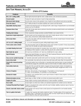
Mower Features
Refer to Figure 2-1:
YourRazorriding moweris designedwith innovativeand
state-of -the art features. Knowing the location and how
thesefeaturesworkwill makehandlingyourmower more
comfortable. Below is a list of the major features we will
be reviewing in this section.
Section 2: Operating Procedures
Razor Features
Figure 2-1
8
16
7
17
14
12
11
14
13
13
18
10
24895
12
3
4
5
6
9
15
19
20
17
Muffler Shield
Is Located Under
the Engine
8
21
21
22
22
1. Blade Engagement Switch
2. Oil Pressure Light
3. Ignition Switch
4. Hour Meter
5. Throttle Lever
6. Choke Lever
7. Battery (Located under the seat)
8. Control Levers
9. Deck Height Indicator
10. Discharge Chute (Guard)
11. Right Deck Cover (Guard)
12. Left Deck Cover (Guard)
13. Anti-Scalp Wheels
14. Deck Adjusting Rod
15. Floor Platform (Guard)
16. Deck Lift Pedal
17. Fuel Tanks
18. Left/Right Fuel Tank Valve
19. Seat Platform (Guard)
20. Muffler Shield (Guard)
21. Bypass Valve Rods
22. Expansion Tank for Hydraulic Oil

11
Section 2: Operating Procedures
1/12/09
Z44 & Z52 (S/N 526171 & Above) Zero Turning Radius Mowers Riding Mowers Accu-Z Razor
®
357-187M
Land Pride
Table of Contents
Operating Check List
Hazard control and accident prevention are dependent
upon awareness, concern, prudence and proper training
involved in operation, transport, maintenance and
storage of the riding mower. Therefore, it is absolutely
essential that no one operates the mower without first
havingread, fully understoodand become totallyfamiliar
with the Operator’s Manual. Make sure the operator has
paid particular attention to:
• Important Safety Information, pgs. 1 to 6
• Section 1: Assembly & Set-up, pg. 8
• Section 2: Operating Procedures, pgs. 10 to 18
• Section 3: Adjustments, pgs. 19 to 26
• Section 5: Maintenance & Lubrication,pgs. 29to42
Before beginning to operate your mower the following
Operating Checklist should be performed:
Instrumentation
Engine Oil Pressure Light
Refer to to Figure 2-2:
This light comes on when ignition switch is placed in
RUN position and stays lit until the engine is running with
a safe oil pressure. Shut engine off immediately if light
comes on during operation. Locate and correct the
problem.
Hour Meter
Refer to Figure 2-2:
Registers1/10hourincrementsupto9,999.9totalhours.
Themeterisconnected totheignitionswitchandrecords
accumulative time only while the engine is running. See
“Maintenance Schedule” on page 30.
Controls
For general location of the controls described in this
section, refer to Figure 2-1 on page 10 and Figure 2-2 on
page 11.
!
WARNING
Do not operate mower while smoking!
Operating Checklist
✔ Check Reference
Read “Important Safety Information”
Page 1
Read “Operating Procedures”
Page 10
Lubricate mower as needed. Refer to Lubrication.
Page 41
Check mower safety start interlock system daily
prior to operation.
Page 13
Check mower initially and periodically for loose
bolts & pins, Torque Values Chart.
Page 48
Make sure all guards and shields are in place.
Page 10
Check blade for nicks and sharpness.
Page 39
Ignition Switch
Refer to Figure 2-2:
A three position ignition switch: off, run, and start is
provided.Withkeyinserted,rotateitclockwise toSTART
position; release key when engine starts, and switch will
automatically return to RUN position. Turn key
counterclockwise to OFF position to stop engine.
Throttle
Refer to Figure 2-2:
A cable is linked from engine to throttle for controlling
engine speed. Move throttle lever forward to increase
enginerpm and rearwardto decrease rpm. Alwaystravel
and cut grass with throttle set at full engine rpm speed.
Slow down travel speed by pulling back on the control
levers. Slow engine rpm speed only if mower is not
traveling or powering the cutting blades.
Control Panel
Figure 2-2
Choke
Refer to Figure 2-2:
A cable is linked from engine to choke knob to choke the
engine during starting. When choke control knob is
down, the choke is off (engine running position). When
controlknob is pulledup, the choke ison (engine starting
position). Shut choke off soon after engine has started.
IMPORTANT: Always operate throttle at full engine
rpm while traveling or cutting grass. Slow engine
rpm may overheat engine and hydraulic pumps.
23686
Engine Oil
Pressure Light
Ignition Switch
Hour Meter
Blade
Engagement
Switch
Choke
Throttle
IMPORTANT: DO NOT operate mower with choke
pulled up or on. (engine starting position).

12
Section 2: Operating Procedures
Z44 & Z52 (S/N 526171 & Above) Zero Turning Radius Mowers Riding Mowers Accu-Z Razor
®
357-187M
1/12/09
Land Pride
Table of Contents
Blade Engagement Switch
Refer to Figure 2-2:
Theblade engagement switch engages the deck blades.
Pullswitch uptoengage bladesandpush switchdownto
disengage the blades.
Left/Right Fuel Tank Valve
Refer to Figure 2-3:
Located behind the seat on one side is the Left/Right
Fuel Tank Valve for controlling which fuel tank is in use.
The valve lever must be over one of the two arrows to
supply fuel to the engine. Arrows point to the fuel tank
beingused.Switchvalve fromonetankto theotherwhen
tankin use is aboutout of fuel. Themower does not have
tobeturnedofftomake theswitch.See“FuelSystem”on
page 35 for more information.
Left/Right Fuel Tank Valve
Figure 2-3
Control Levers
Refer to Figure 2-4 and Figure 2-5:
The control levers are used to steer, accelerate, brake,
change direction and set the park brake.
Always set both control levers in park position by
spreading full apart before getting off the mower and
alwaysleavecontrolleversinparkuntilseatedandready
to start traveling.
Pullcontrolleverstogetherat thehandlestoreleasepark
brakes. Move control levers either forward or rearward
from neutral position to start moving.
IMPORTANT: Never engage blades with engine
running at high rpm or when the deck is under load.
Clutch, belts or deck could be damaged.
23688
Left/Right Fuel Tank Valve
Center Position “O”
as Shown is OFF
!
WARNING
The park brake is not designed to hold the mower on steep
slopes.
Move the control levers to neutral to stop and fully apart
to set park brakes.
See “Driving the Mower” on page 14 for a detailed
description of operating the control levers.
Control Levers
Figure 2-4
.
Control Levers Spread Fully Apart
Figure 2-5
IMPORTANT: Both control lever must be spread
fully apart before park brakes are applied.
24894
Control Levers With
Handles Placed In
Operating Position
Neutral Slot
24903
Spreading the control levers fully apart
automatically sets the park brakes.

13
Section 2: Operating Procedures
1/12/09
Z44 & Z52 (S/N 526171 & Above) Zero Turning Radius Mowers Riding Mowers Accu-Z Razor
®
357-187M
Land Pride
Table of Contents
Deck Lift Pedal
Refer to Figure 2-6:
The deck lift pedal is used to raise and lower the deck
and to set deck cutting height.
1. Pushing on the deck lift pedal with your foot will raise
the deck.
2. Using the deck height indicator, place deck height
locking pin into the desired cutting height hole.
3. Lower deck gently against locking pin.
Whengoing over obstructions, push the deck lift pedal to
raise the deck. Go around the obstruction if the deck will
not raise high enough. Never mow over obstructions
you are not certain the deck will clear.
.
Deck Lift Pedal
Figure 2-6
Safety Start Interlock System
The mower is equipped with a safety start interlock
system consisting of park switches, seat switch and
blade engagement switch. This system is an important
mower safety feature designed to prevent runaway or
accidental entanglement.
If blade engagement switch is ON or if a control arm is
out of park and the operator gets off the seat, the engine
will stop.
IfbladeengagementswitchisOFFandbothcontrolarms
are in park and the operator gets off the seat, the mower
engine will continue to run.
Thesafetystartinterlocksystemshouldbecheckeddaily
prior to operation and repaired immediately if it
malfunctions. Inspect system as follows:
1. The operator must be on the seat when testing the
seat safety switch.
2. Spread both control levers fully apart.
23621
Deck Lift
Pedal
DeckHeight
Indicator
DeckHeight
Locking Pin
3. Start mower engine per instructions outlined in
section on Engine Starting below. Allow engine to
warm up to operating temperature.
4. With blade engagement switch down (OFF), and
controlleversspreadfullyapart(setinparkposition),
slowlyraise off the seat. The engine should continue
to run.
5. Pull the right control lever in and slowly raise off the
seat. The engine should stop within five seconds.
6. With control levers spread fully apart, restart engine.
7. Pull the left control lever in and slowly raise off the
seat. The engine should stop within five seconds.
8. With control levers spread fully apart, restart engine.
9. With control levers set in park position (fully apart)
and engine running at a slow idle, pull up on the
blade engagement switch to turn blades (ON).
Slowly raise off the seat. The engine should stop
within five seconds.
10. Replace seat safety switch if switch failed to operate
properly in any of the above steps and if no other
cause such as damaged wiring can be determined.
11. Contact your local Land Pride Dealer if the problem
cannot be located.
Engine Starting
!
WARNING
Never leave the machine unattended with key in ignition
switch.
The Razor safety start interlock system is also designed
to protect the operator and others from accidental injury
due to unintentional engine starting.
The following steps are correct procedures for starting
the engine. If difficulty is encountered, contact your local
Land Pride Dealer.
1. Perform daily pre-operation checks. (See
“Operating Check List” on page 11.)
2. Make sure both control levers are in park position,
and blade engagement switch is disengaged (OFF).
3. Set throttle at approximately 1/2 open position.
NOTE: The starting motor will not engage until both
control levers are spread fully apart (Set in park
position) and blade engagement switch is in down
position (OFF).
The engine will stop if for any reason the operator
should become unseated when one or more control
leversarenotinparkpositionorifblade engagement
switch is (ON).
NOTE: Use choke when engine is cold or if warm
engine fails to start within 5 seconds of cranking.
Avoid flooding. Operate engine without choking as
soon as possible.

14
Section 2: Operating Procedures
Z44 & Z52 (S/N 526171 & Above) Zero Turning Radius Mowers Riding Mowers Accu-Z Razor
®
357-187M
1/12/09
Land Pride
Table of Contents
4. Insert key in ignition switch and rotate clockwise to
engage starting motor. Release key when engine
starts.
5. Perform test to make sure safety start interlock
system is operating properly. Refer to “Safety Start
Interlock System” on Page 13.
6. As soon as engine begins to run, check to make
certain the oil warning light is off. If not, stop engine
immediately and check for the cause. Refer to
“Troubleshooting” on page 46.
7. Allow engine to idle a few minutes before advancing
throttle and/or engaging blades.
8. Before stopping the engine:
• Disengage blade engagement switch.
• Place both control levers in park position.
• Throttle back to low idle for one minute to allow
accumulated raw fuel to escape muffler during
engine slow down.
• Rotate ignition key counter-clockwise to (OFF)
position.
• Remove key from switch before leaving the seat.
Driving the Mower
!
DANGER
Never make sudden stops or sudden reversing of direction,
especially when going down a slope. The steering is designed
for sensitive response. Rapid movement of control levers in
either direction could result in a reaction that can cause
serious injury.
!
DANGER
Never make sudden speed changes from reverse to forward.
Always push control levers forward gently to avoid sudden
change in speed. Any sudden forward speed change can cause
the front wheels to raise off the ground resulting in loss of
control, mower damage and/or personal injury.
To Start and Increase Speed
Refer to Figure 2-7 on page 15:
After starting the engine, engage control levers by
moving the handles towards each other. This moves the
levers from park position to neutral position and makes
them ready for steering while traveling.
Moving control levers an equal distance away from
neutral will increase travel speed.
• Start forward travel by gently pushing on the control
levers. The further forward the control levers are
pushed the faster the travel speed.
NOTE: The engine starter should notbe operated for
periods longer then 30 seconds at a time. An interval
of at least two minutes should be allowed between
such cranking periods to protect the starter from
overheating and burn-out.
• Start backing up by gently pullingon the control levers.
Thefurther backthecontrol leversare pulled thefaster
the travel speed.
To Decrease Speed and Stop
!
WARNING
In the event of a system shutdown while mowing, move control
levers to neutral and spread them fully apart to aid in slowing
and stopping the mower. See Figure 2-5 on page 12. Also
turning the ignition switch to off will set the rear park brakes
without positioning of the control levers in park.
Refer to Figure 2-7 on page 15:
Moving control levers an equal distance towards neutral
will decrease travel speed.
• When moving forward, pull back gently on control
levers to decrease speed. The further back the control
levers are pulled the slower the travel speed until
neutral is reached.
• When backing up, push forward gently on control
levers to decrease speed. The further forward the
control levers are pushed the slower the travel speed
until neutral is reached.
• Move control levers to neutral to stop.
• Spread bothcontrol leversfully aparttoapply rearpark
brakes.
To Steer
Refer to Figure 2-7 on page 15:
• To Steer Straight While Traveling Forward:
Push control levers forward an equal distance.
• To Steer Straight While Backing Up:
Pull control levers rearward an equal distance.
• To Turn Left While Traveling Forward:
Moveright control lever farther forwardfrom neutral
than the left control lever.
• To Turn Left While Backing Up:
Move right control lever farther back from neutral
than the left control lever.
• To Turn Right While Traveling Forward:
Move left control lever farther forward from neutral
than the right control lever.
• To Turn Right While Backing Up:
Move left control lever farther back from neutral
than the right control lever.
• To Make A Pivot Turn:
Move one control lever forward and the other
control lever back of neutral, this will allow the drive
wheels to counter-rotate.
IMPORTANT: Parks brakes will automatically apply
when ignition switch is turned off. This allows the
operator to set park brakes quickly without returning
control levers to park.

15
Section 2: Operating Procedures
1/12/09
Z44 & Z52 (S/N 526171 & Above) Zero Turning Radius Mowers Riding Mowers Accu-Z Razor
®
357-187M
Land Pride
Table of Contents
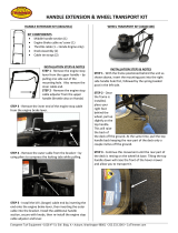
Moving Mower with Stalled Engine
Refer to Figure 2-8:
Each hydro-drive is equipped with a bypass valve for the
purpose of moving the mower when the engine is
inoperable.
Moving the mower with a good battery
1. Pull out on the bypass valve rods and lift them into
the slot to lock in position. Both bypass valve rods
are located at the rear of the engine platform.
2. Positionboth controlleversinneutralwiththe handles
together.
3. Turn ignition switch to on. Do not start the mower.
4. Manually move mower by hand or with a winch.
Moving the mower with a bad battery
1. Pull out on the bypass valve rods and lift them into
the slot to lock them in position.
Refer to Figure 5-6 on page 34:
2. Remove hair pin cotter (#5), flat washer (#3) and
clevis pin (#1) from actuator arm (#2). Be certain to
do this to both the right and left transaxles. Push
brake lever arms up to release park brakes.
3. The mower should move with moderate pressure
once the park brakes have released.
4. Manually move mower by hand or with a winch.
Bypass Valve
Figure 2-8
IMPORTANT: Do not tow machine. Move it by hand
or use a winch and load it on a trailer.
IMPORTANT: Following repairs, always make
certain the two bypass valves are returned to their
operating position and actuator pins are reinstalled.
24895
Bypass Valve Rods
Figure 2-7
Front of Mower Faces This Direction
23923

16
Section 2: Operating Procedures
Z44 & Z52 (S/N 526171 & Above) Zero Turning Radius Mowers Riding Mowers Accu-Z Razor
®
357-187M
1/12/09
Land Pride
Table of Contents
Safe Operating Instructions
The safe operation of any machinery is a big concern to
all consumers. Your Zero Turn Riding Mower has been
designedwith manybuilt-insafetyfeatures.However,no
one should operate this mower before carefully reading
this Operator’s Manual. Also read all instructions noted
on the safety decals.
▲ Be familiar with all functions of this mower.
▲ Do not operate a mower with damaged parts. Repair
all damaged and defective parts before putting mower
back in to service.
▲ Keep all bystanders away from this mower during
operation.
▲ Do not allow anyone to operate this mower who has
not fully read and comprehended this manual and who
has not been properly trained in the safe operation of
this mower.
▲ Do not allow anyone under 16 years of age to operate
this mower.
▲ No riders allowed. Carrying a rider can result in injury
and/or death to the rider and operator.
▲ Do not operate mower while drinking or under the
influence of alcohol or drugs.
▲ Always park on level ground, place both control levers
in park position and remove ignition key before leaving
the mower.
▲ Do not leave mower unattended with engine running.
▲ Always operate mower with belt guards installed. Do
not leave pulleys and belts exposed.
▲ Wear snug-fitting clothing to avoid entanglement with
moving parts.
▲ Keep hands, feet, long hair, clothing and jewelry away
from moving parts and obvious pinch points to avoid
getting caught.
▲ Always be aware of and avoid tree limbs and brush
that have a potential of hitting and/or poking one while
riding the mower. Serious body harm could result.
▲ Always wear long pants, safety glasses and safety
shoes. Some conditions may warrant extra safety gear
to be worn such as safety helmets.
▲ Do not touch engine, engine exhaust pipe and/or
muffler while they are hot.
▲ Use extreme caution when driving through dry grass,
brush and other fire hazard materials. Never stop or
park over combustible materials. Keep grass and
brush from collecting on and around engine and
muffler parts.
▲ Battery fumes are explosive. A spark will ignite battery
fumes. Wear a face shield when charging or jumping a
battery. Follow all battery safety rules outlined in this
manual.
▲ Avoid battery acid spills. Do not get battery acid on
eyes, face, or other body parts. Flush eyes and other
body parts immediately with water for at least 15
minutes if battery acid has gotten on them.
▲ Do not operate this mower on streets, highways, public
roads, or where it may be a hazard to faster moving
traffic.
▲ Never attempt wheelies, jumps, or other stunts. Never
drive recklessly. Always operate your mower at a safe
speed that will allow you to maintain control.
▲ Never modify engine RPM, or any parts on the mower
without authorization. Unauthorized modifications will
voidwarrantyto all parts directly and indirectly affected
by the modification.
▲ Do not pull a trailer or implement exceeding a gross
weight of 300 pounds and 50 pounds tongue weight.
Loss of control may result. Do not make turns so
sharp as to cause trailer or implement being towed to
come in contact with the mower. Damage may result.
▲ Do not attach an implement, trailer or other device to
the hitch that will produce negative tongue weight.
▲ Do not tow the mower with its wheels on the ground.
Always tow the mower loaded on a trailer.
▲ Use extreme caution when cresting hills or when
visibility is limited. Proceed slowly until you are sure
conditions immediately ahead are safe.
▲ Reduce speed on hilly, rough, wet, slick or unstable
ground. Do not operate mower on slopes over 15
o
.
▲ Do not operate the mower at night. With poor visibility,
night operation can lead to a serious accident.
▲ When refueling use a UL listed container that has a
screen or filter. Set container on the ground before
fueling to eliminate static discharge. Do not use
Methanol fuel.
▲ Do not smoke or use electrical devices including cell
phones while refueling.
▲ Always maintain proper tire inflation. See "Tires" on
page 32.
▲ Always disconnect the negativebattery terminal before
making adjustments to the mower electrical system or
welding on this mower.
▲ Always check wheel lug nut torque values two hours
after initial operation and two hours after each tire
repair and/or replacement. Routinely check lug nut
torque valves every 50 hours of operation. See
"Torque Values" on page 19.
▲ Support this mower securely before working beneath.
Chock the wheels to prevent the mower from rolling.

17
Section 2: Operating Procedures
1/12/09
Z44 & Z52 (S/N 526171 & Above) Zero Turning Radius Mowers Riding Mowers Accu-Z Razor
®
357-187M
Land Pride
Table of Contents
!
DANGER
Prior to operating the mower the operator should be
thoroughly familiar with the proper use and operation of the
equipment, should read the manual completely and
thoroughly, and should have attempted slow moving
maneuvers to become familiar with the operation of the
equipment before attempting normal speed operation. An
inexperienced operator should not mow on slopes or on
uneven terrain.
!
WARNING
Do not operate the mower while wearing any type of loose
fitting clothing. Always wear safety glasses, clothing that does
not hang loosely, and shoes or boots when operating this
machine.
!
WARNING
The tailpipe and muffler are very hot and can ignite dry
grasses, brush and other flammable materials. Always keep
the area around the muffler and tailpipe clear of debris. Allow
the muffler and tail pipe to cool completely before removing
any debris to prevent sever burns to the body.
!
WARNING
Never direct discharge of material from mower deck towards
bystanders.
!
WARNING
Never operate the mower deck with discharge chute removed
or in raised position.
!
WARNING
Always check area to be mowed for rocks and other debris
before mowing.
The mower’s control levers are very responsive. For
smooth operation, move levers slowly, avoid sudden
movement. Skill and ease of operation come with
practice and experience.
Inexperienced operators may have a tendency to
over-steer and lose control. Slow-moving practice
maneuvers are recommended to become familiar with
these characteristics before attempting normal speed
operation.
Sharp depressions or raised obstacles (such as gutters
or curbs) should not be directly approached at high
speed in an attempt to jump them as the operator could
be thrown from the mower. Approach at a slow speed
andangleonedrive wheelattheobstruction. Continueat
an angle until both wheels clear the obstruction.
When turning on soft wet turf, keep both wheels rolling
either forward or backward. Pivoting on one stopped
wheel can damage turf.
Peak mowing performance is maintained when the
throttle is set at full rpm. This gives maximum power to
the drive wheels and deck when needed. Use the control
levers to control ground speed rather than engine rpm.
Keep blades sharp. Many problems with incorrect
cutting patterns are due to dull blades or blades which
have been sharpened incorrectly. Information on
sharpening blades islisted inthis manual’s maintenance
section. In addition, most communities have individuals
or companies which specialize in sharpening mower
blades. Blade sharpness should be checked daily.
Use high blade speed. Your Razor is designed to
operate at full throttle. The throttle setting directly
controlsblade speed.The highestblade speedgenerally
gives the best cut.
Select a mowing pattern that discharges cut grass
away from uncut grass. Generally, this means using a
patternutilizingleftturns because the mower discharges
cut grass to the right. Refer to Figure 2-9. In any case,
avoid discharging cut grass onto an unmowed area
because grass is then mowed twice. Mowing twice puts
an unnecessary load on the mower and reduces mowing
efficiency.
Discharge Chute
Figure 2-9
24912
Discharge Chute

18
Section 2: Operating Procedures
Z44 & Z52 (S/N 526171 & Above) Zero Turning Radius Mowers Riding Mowers Accu-Z Razor
®
357-187M
1/12/09
Land Pride
Table of Contents
Mower Deck Operation
!
DANGER
Never attempt to make any adjustments to the mower deck
while the engine is running or when the blades are engaged.
Mower blades cannot be seen and are located very close to
deck housing. Fingers and toes can be cut off instantly.
With the engine running at a medium speed, engage
blades (Refer to Figure 2-10). Advance engine throttle to
full rpm once the blades have become fully engaged.
Blade Engagement Switch
Figure 2-10
NOTE: Engaging the blades at high engine rpm or
when under heavy load (in tall grass for example)
can cause belts to slip, resulting in premature wear
or possible damage.
23686
Blade
Engagement
Switch
General Operating Information
AfterthoroughlyfamiliarizingyourselfwiththeOperator’s
ManualandcompletingtheOperator’sChecklist,youare
almost ready to begin mowing.
Approach the mower from the front. Spread the control
levers fully apart if they aren’t already in the wide-open
position. Taking care not to step on either side of the
mower deck, step up on the operator’s platform and
comfortably seat yourself. With both control levers still
wideapartreach forthethrottle andchokecontrol toyour
right side. Position the throttle control at half throttle and
pull the choke to the “up/on” position. Insert your ignition
key and rotate the ignition key clockwise until you hear
the engine begin to start. Release the ignition key and
pushthechoketo“down/off”position.Allowtheengineto
warm up momentarily. If your mower has just been
running and the engine is already warm, using the choke
is usually not necessary.
With the engine at half throttle, pull the control levers in
tobringboth controlleversequally togetherin theneutral
position just in front of you. It’s now time to test your
steering skills. Gently push both control levers equally
forward. The farther forward you push the levers the
faster you will go. Pull back equally and you will slow
down coming to a stop when you reach the neutral
position. Now slowly pull the levers back toward your
body past neutral position. The mower will reverse
direction and increase in speed as you pull further back.
If you push one lever forward and pull one lever back the
mower will do a Zero turn in the direction of the control
lever closest to your body. Now take a few moments in a
safe area to practice steering your mower with the
engine still at half throttle. Gradually increase your
throttle speed until you feel totally confident in your
mower steering and handling ability.
After removing all obstacles from the lawn, it is now time
to cut the grass. With your mower at half throttle, place
your right foot on the deck lift pedal and release and
lower the deck to your preset cutting height. With your
righthand, pullup onthe cuttingblade engagementknob
and increase the engine speed to full throttle. You may
now begin mowing.
When you are done mowing or just want to take a break,
make sure you:
• Park on level ground
• Disengage the cutting blades
• Throttle back
• Move the control levers to wide-open
• Turn the engine off
• Remove the key
• Step carefully off the front of the machine.
/