WARNING
Electric Shock Hazard.
Keep water and other liquids from entering the inside
of the equipment. Liquid inside the equipment could
cause an electrical shock
Do not spray water or cleaning products. Liquid could contact the
electrical components and cause a short circuit or an electrical shock.
Do not use equipment if power cord is damaged or has been modied
SAFETY
READ ALL INSTRUCTIONS BEFORE USE. FAILURE TO
FOLLOW THESE PRECAUTIONS COULD RESULT IN INJURY TO
YOURSELF AND OTHERS
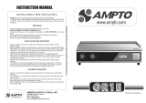
Part SCE
No.
Part No.
1 82-EG6-SS-BDYAS BODY ASSEMBLY
2 1-EGO-150 GRILLER THERMOSTAT
3 1-PL-BMA0001 PILOT LIGHT
4 3-CPB-FTA0400 CONTROL KNOB
5 4-CPI-TEMP FACIA PANEL INSERT
6 3-CPF-AXIS CONTROL PANEL FACIA
7 82-EGC-SS-THAND FAT TRAY
8 4-DL-L-AXIS ANVIL AXIS LOGO
9 82-EGC-MS-ECBKT ELEMENT CLAMP
10 82-NGC-SS-PCLMP PROBE CLAMP
11 82-EG6-MS-BOTCV BOTTOM COVER
12 82-EG6-MS-GECOV ELEMENT COVER
13 3-25-INSU-GRILL INSULATION PAD
14 5-1500W-GRILLER
GRILLER ELEMENT
15 11-DTF- FTA0400 FAT TRAY SHIELD
16 3-ADJ-PF ADJUSTABLE FEET
17 2-PC-CE-CP POWER CORD
18 3-CG-1.5 CABLE GRIP
19 3-FF-CB TERMINAL BLOCK
20 82-EHR-SS-GTASS 600 GRIDDLE TOP HALF RIBBED
Description
600MM ELECTRIC GRILLER HALF RIBBED
MODEL CODE : FTA2600 R03
1. When this appliances is to be positioned in close proximity
to a wall, partitions, kitchen furniture, decorative nishes, etc.
it is recommended that they be made of non-combustible mate-
rial. If not, they shall be clad with a suitable non-combustible
heat insulating material, and the closest attention be paid to re
prevention regulations.
2. Use the appliances on an individual 15A mains outlet only.
DO NOT OVERLOAD THE CIRCUIT.
3. Ensure that the equipment and the power supply cord does not
come into contact with hot surfaces.
4. Supervision is necessary when the appliance is used in close
proximity to children.
5. If the supply cord is damaged, it must be replaced with a new
cord assembly available from the suppliers agent.
6. Use only earthed outlets matching the serial plate voltage.
7. Have equipment installed by a qualied personnel in accordance
with local codes and ordinances.
8. Use equipment in a at level position.
9. Do not operate unattended
10. The equipment may be hot, even though the pilot light is not on.
11. Do not operate if equipment has been damaged or is malfunc-
tioning in any way.
12. These appliance sare designed to run only on alternating current
(A.C.) DO NOT CONNECT TO DIRECT CURRENT (D.C)
265