Page is loading ...

OmniRow™ Installation Manual
White MultiRow

While every effort has been made to ensure the accuracy of this document,
Raven Industries assumes no responsibility for omissions and errors. Nor is any
liability assumed for damages resulting from the use of information contained
herein.
Raven Industries shall not be responsible or liable for incidental or consequential
damages or a loss of anticipated benefits or profits, work stoppage or loss, or
impairment of data arising out of the use, or inability to use, this system or any of
its components. Raven Industries shall not be held responsible for any
modifications or repairs made outside our facilities, nor damages resulting from
inadequate maintenance of this system.
As with all wireless and satellite signals, several factors may affect the availability
and accuracy of wireless and satellite navigation and correction services (e.g.
GPS, GNSS, SBAS, etc.). Therefore, Raven Industries cannot guarantee the
accuracy, integrity, continuity, or availability of these services and cannot
guarantee the ability to use Raven systems, or products used as components of
systems, which rely upon the reception of these signals or availability of these
services. Raven Industries accepts no responsibility for the use of any of these
signals or services for other than the stated purpose.
Disclaimer

Table of Contents
Manual No. 016-3001-012 i
Chapter 1 Important Safety Information................................................. 1
Hydraulic Safety ........................................................................................................................2
Electrical Safety ........................................................................................................................2
Chapter 2 Introduction............................................................................. 3
Preparing for Installation ...........................................................................................................3
Recommendations ..............................................................................................................3
Tools Needed ......................................................................................................................4
Point of Reference ............................................................................................................... 4
Hydraulic Fittings .......................................................................................................................4
Chapter 3 Hydraulic System Installation................................................ 5
Preparing for Installation ...........................................................................................................5
Disassemble the Planter’s Drive System ..................................................................................6
Install the OmniRow Hydraulic Motors ......................................................................................8
Install the Fittings on the PWM Valve ..................................................................................8
Install the PWM Valve and Fittings on the OmniRow Hydraulic Motor ..............................10
Install the Drive Couplers ..................................................................................................10
Mount the OmniRow Hydraulic Motors .............................................................................. 11
Install the Pressure Gauge Test Kit .........................................................................................14
Install the OmniRow Hydraulic Valve ......................................................................................15
Install the Fittings on the Valve ..........................................................................................15
Mount the OmniRow Hydraulic Valve ................................................................................16
Install the Planter Row Unit Pressure and Tank Hoses ...........................................................17
Install the OmniRow Valve Pressure and Tank Hoses ............................................................20
Connect the Hydraulic Hoses to the Tractor ...........................................................................21
Open Center Hydraulic System .........................................................................................22
Closed Center Hydraulic System ......................................................................................22
Chapter 4 Wiring Installation................................................................. 23
Install the Tractor Cables ........................................................................................................23
Install the OmniRow Harness Cables ......................................................................................24
Install the Proximity Switch ......................................................................................................25
Install the OmniRow Nodes .....................................................................................................26
System Installation Verification ................................................................................................26

Table of Contents
ii White MultiRow OmniRow™ Installation Manual

CHAPTER
1
Manual No. 016-3001-012 1
C hapter 1
Important Safety
Information
Read this manual and the operation and safety instructions included with your implement and/or controller
carefully before installing the OmniRow™ system.
• Follow all safety information presented within this manual.
• If you require assistance with any portion of the installation or service of your Raven equipment, contact
your local Raven dealer for support.
• Follow all safety labels affixed to the OmniRow system components. Be sure to keep all safety labels in
good condition and replace any missing or damaged labels. To obtain replacements for missing or damaged
safety labels, contact your local Raven dealer for support.
When operating the machine after installing OmniRow, observe the following safety measures:
• Be alert and aware of surroundings.
• Do not operate OmniRow or any agricultural equipment while under the influence of alcohol or an illegal
substance.
• Remain in the operator’s position in the machine at all times when OmniRow is engaged.
• Disable OmniRow when exiting from the operator’s seat and machine.
• Do not drive the machine with OmniRow enabled on any public road.
• Determine and remain a safe working distance from other individuals. The operator is responsible for
disabling OmniRow when the safe working distance has diminished.
• Ensure OmniRow is disabled prior to starting any maintenance work on OmniRow or the machine.
NOTICE

Chapter 1
2 White MultiRow OmniRow™ Installation Manual
•
When starting the machine for the first time after installing OmniRow, be sure that all persons stand clear, in
case a hose has not been properly tightened.
• Install the enclosed warning labels in a highly-visible area of the planter’s tool bar.
Hydraulic Safety
• Raven Industries recommends that appropriate protective equipment be worn at all times when working on
the hydraulic system.
• Never attempt to open or work on a hydraulic system with the equipment running. Care should always be
taken when opening a system that has been previously pressurized.
• When disconnecting the hydraulic hoses or purging is required, be aware that the hydraulic fluid may be
extremely hot and under high pressure. Caution must be exercised.
• Any work performed on the hydraulic system must be done in accordance with the machine manufacturer’s
approved maintenance instructions.
• When installing OmniRow hydraulics or performing diagnostics, maintenance, or routine service, ensure
that precautions are taken to prevent any foreign material or contaminants from being introduced into the
machine’s hydraulic system. Objects or materials that are able to bypass the machine’s hydraulic filtration
system will reduce performance and possibly damage the hydraulic valves.
Electrical Safety
• Always verify that the power leads are connected to the correct polarity as marked. Reversing power leads
could cause severe damage to the equipment.
• Ensure that the power cable is the last cable to be connected.
WARNING
CAUTION

CHAPTER
2
Manual No. 016-3001-012 3
C hapter 2
Introduction
Congratulations on your purchase of the Raven OmniRow system! This system is designed to allow you to
manage variable-rate seeding, automatic on/off planter control, and real-time seed monitoring, eliminating
costly skips, doubles, and over-plants.
This manual applies to various White planters equipped with standard White row units and options.
Preparing for Installation
Before installing OmniRow, park the machine on a level, clean, and dry surface. Leave the machine turned off
for the duration of the installation process.
During the installation process, follow good safety practices. Be sure to carefully read the instructions in this
manual as you complete the installation process.
Recommendations
Raven Industries recommends the following best practices before installing or operating the OmniRow system
for the first time, at the start of the season, or when moving the OmniRow system to another machine:
• Ensure the machine’s hydraulic filters have been recently changed and there are no issues with the
machine’s hydraulic system (e.g., pump issues, faulty hydraulic motors, fine metal deposits in the hydraulic
hoses, etc.).
• Cycle the planter’s folding operations to ensure that hoses are not rubbing on or interfering with moving
parts and hydraulic fluid is not leaking from the system.
• If the planter is equipped with row cleaners/coulters, verify travel of row cleaners/coulters do not interfere
with the OmniRow equipment.
Raven Industries recommends the following best practices when installing the OmniRow system.
• Use part numbers to identify the parts.
• Do not remove the plastic wrap from a part until it is necessary for installation.
• Do not remove plastic caps from a part until it is necessary for installation.

Chapter 2
4 White MultiRow OmniRow™ Installation Manual
Tools Needed
The following tools are recommended for installation of the OmniRow system:
• SAE standard-sized wrenches/sockets
• Metric wrenches/sockets
• Allen wrenches
• Cable ties
• Set of tools
Point of Reference
The instructions in this manual assume that you are standing behind the planter, looking toward the planter’s
hitch or tractor. The planter row units referenced in the manual are numbered from left to right, with the left row
unit being #1.
Hydraulic Fittings
This manual may reference the following types of hydraulic fittings:
• SAE O-Ring fittings
• ORFS (O-Ring Face Seal) fittings
• JIC fittings
TABLE 1. Hydraulic Fitting Conversion Chart
Dash Size JIC and UNO SAE ORFS NPT BSP
04
9/16” 1/4” 1/4”
06 3/8” 3/8” 11/16” 3/8” 3/8”
08 1/2” 1/2” 13/16” 1/2” 1/2”
10
5/8” 1” 5/8”
12 3/4” 3/4” 1-3/16” 3/4” 3/4”
16
1-7/16” 1” 1”
JIC fitting (M)
ORFS fitting
SAE O-ring fitting

CHAPTER
3
Manual No. 016-3001-012 5
C hapter 3
Hydraulic System
Installation
Preparing for Installation
Important: Refer to the implement’s operation manual before changing the connection or configuration of any of
the existing hydraulic hoses.
For the OmniRow system to function properly, its hydraulic tank line must connect to a low pressure return
connection on the tractor that prohibits the tank pressure from exceeding 200 psi. A motor return connection is
the ideal connection for the OmniRow system because it prevents the pressure from being reversed to the
system. The vacuum fan motor on the planter is often installed on this connection. If this is the case, it is likely
that the fan return line can be connected to the SCV return port next to the fan pressure line. If there is no
available return connection, one will have to be added to the tractor. Contact your local tractor service provider
for more information.
FIGURE 1. Low Pressure Motor Returns

Chapter 3
6 White MultiRow OmniRow™ Installation Manual
Disassemble the Planter’s Drive System
Note: The OmniRow system may require the use of some of the machine’s hex drive shafts.
Modifications to the shafts must be made to divide the planter into specific sections. Refer to the
planter-specific guide included with the OmniRow installation kit to identify the planter sections.
Excluding the hex shafts, the planter’s existing drive system is not required for operation once the
OmniRow system is installed. Although it is not required for the entire existing ground drive or
hydraulic transmission(s) to be removed from the planter, it is recommended to do so to help
prevent any interference between the existing planter drive system and the OmniRow system.
FIGURE 2. Machine’s Existing Hex Shaft
1. Using the planter-specific installation guide included with the OmniRow installation kit, identify the planter
sections the OmniRow system will operate.
Note: Identify which sections will use the machine’s existing hex shafts and which sections will use the
hex shafts supplied in the kit.
Note: Before cutting shafts, review the planter’s shaft layout. Some shafts may be switched around,
eliminating the need to cut some shafts.
2. For the sections that will be using the existing hex shaft, remove the drive shaft couplers or cut the 3/4” hex
shaft as needed so that the planter is separated into the appropriate sections.
Important: Leave the existing sprocket on the right side of the row unit. The OmniRow system will utilize it and the
existing drive chain to drive the seed meter.
3. Determine to which row units the OmniRow motors will be mounted and remove the 3/4” hex drive shaft
from those row units.
4. For sections that will be using the supplied hex shaft, remove the machine’s existing hex shaft.
3/4” Hex
Drive Shaft
Planter’s
Existing Drive
Chain

3
Manual No. 016-3001-012 7
Hydraulic System Installation
FIGURE 3. Machine’s Supplemental Support Bearings
5. Supplemental support bearings (from the left side of the planter row units, opposite the seed meter drive
sprocket) can be removed as needed if they interfere with the OmniRow installation.
Important: Supplemental support bearings may be required to help support section shafts. Refer to the supplied
installation guide to determine if and where support bearings need to be placed.
Note: Supplemental support bearings are generally located next to folding or flex points, or where drive
chains from the transmission attach to the main hex shaft.
FIGURE 4. Components to be Removed as Needed

Chapter 3
8 White MultiRow OmniRow™ Installation Manual
6. Remaining jack shafts, transmissions, and/or OEM hydraulic motors can be removed as needed if they
interfere with the OmniRow installation.
Install the OmniRow Hydraulic Motors
Install the Fittings on the PWM Valve
End Row Units
FIGURE 5. Fittings and PWM Valves Installed - End Row Units
1. Refer to the figure and table above to install the fittings in the appropriate ports of the PWM valve (P/N 063-
0131-140) for the end row units.
2. Tighten the fittings to ensure they are securely installed.
Fitting Part Number Port
Fitting - 9/16” SAE O-Ring (M) to 9/16” SAE O-Ring (M) Straight Adapter 333-0012-240 1
Fitting - 3/4” JIC (M) to 9/16” SAE O-Ring (M) 90° Elbow 333-0012-071 2
P/N 333-0012-071
P/N 333-0012-240

3
Manual No. 016-3001-012 9
Hydraulic System Installation
Middle Row Units
FIGURE 6. Fittings Installed PWM Valve - Middle Row Units
1. Refer to the figure and table above to install the fittings in the appropriate ports of the PWM valve (P/N 063-
0131-140) for the middle row units.
2. Tighten the fittings to ensure they are securely installed.
Fitting Part Number Port
Fitting - 9/16” SAE O-Ring (M) to 9/16” SAE O-Ring (M) Straight Adapter 333-0012-240 1
Fitting - 3/4” JIC (M) to 9/16” SAE O-Ring (M) to 3/4” JIC (M) Tee Adapter 333-0012-315 2
Fitting - 3/4” JIC M/F 90° Elbow 333-0012-064
End of
Installed Tee
P/N 333-0012-315
P/N 333-0012-240
P/N 333-0012-064

Chapter 3
10 White MultiRow OmniRow™ Installation Manual
Install the PWM Valve and Fittings on the OmniRow Hydraulic
Motor
FIGURE 7. PWM Valve and Fittings Installed
1. Install the PWM valve assembly in the pressure port of the OmniRow hydraulic motor (P/N 416-8000-001).
2. Install a 3/4” SAE O-ring (M) to 3/4” JIC (M) straight adapter fitting (P/N 333-0012-093) in the tank port of
the OmniRow hydraulic motor.
3. Middle Row Units Only - Install a 3/4” JIC M/M/F swivel run tee adapter fitting (P/N 333-0012-039) on the
fitting installed in the tank port of the OmniRow hydraulic motor.
Install the Drive Couplers
1. Based on the planter’s configuration, determine which side of the hydraulic motor will drive the hex shaft.
FIGURE 8. Drive Coupler Assembly
2. Insert the coupler (P/N 107-0172-043) into the side of the motor that will drive the hex shaft.
3. Install the hex spacer (P/N 107-0172-017) in the opposite side of the motor.
4. Insert a 1/4”-20 UNC-2 x 3-1/2” bolt (P/N 311-0050-115) in the shaft coupler and through the hex spacer.
5. Install a 2” OD x 1/4” ID washer (P/N 313-2300-136) on the bolt.
6. Secure the assembly with a 1/4”-20 zinc flanged lock nut (P/N 312-1001-168). The final assembly should
appear as shown in Figure 9 below:
Middle Row Unit Assembly
End Row Unit Assembly
P/N 333-0012-039
P/N 333-0012-093
P/N 311-0050-115
P/N 107-0172-043
P/N 107-0172-017
P/N 313-2300-136
P/N 312-1001-168

3
Manual No. 016-3001-012 11
Hydraulic System Installation
FIGURE 9. Final Assembly
Note: If the motor will be tied into hex shafts on both sides of the motor, replace the hex spacer (P/N 107-
0172-017) and washer (P/N 313-2300-136) with another coupler (P/N 107-0172-043). The final
assembly should appear as shown in Figure 10 below:
FIGURE 10. Drive Coupler Assembly - Motor Tied on Both Sides
Mount the OmniRow Hydraulic Motors
Important: Ensure the motor, mounting bracket, and hardware do not come into contact with the parallel linkage
bars or row cleaner/coulter attachments when the row unit travels up and down.
Left Mounting
1. Replace the existing bolts used to secure the support/bearing hanger (f equipped) with the supplied 3/8”-16
x 1-1/2” hex bolts (P/N 311-0054-107).

Chapter 3
12 White MultiRow OmniRow™ Installation Manual
FIGURE 11. Mounting Bracket Installed
2. Mount the motor mounting bracket (P/N 107-0172-003) on the bolts.
3. Secure the motor mounting bracket with the supplied 3/8” zinc flanged lock nuts (P/N 312-1001-164).
FIGURE 12. Hydraulic Motor Installed
4. Mount the hydraulic motor (P/N 416-8001-001) to the motor mounting bracket using 3/8” x 2-1/2” L bolts
(P/N 311-0054-111) and loosely secure with 3/8” zinc flanged lock nuts.
5. Install the 3/4” hex shafts.
Note: Refer to the machine-specific installation guide to determine the section divisions of the planter
and the corresponding 3/4” hex shaft.
6. Secure the hex shafts with existing shaft collars, supplied hex collars (P/N 107-0172-082), and/or cotter
pins on the opposite side of the existing bearing or sprocket that is not next to an OmniRow hydraulic motor.
P/N 107-0172-003

3
Manual No. 016-3001-012 13
Hydraulic System Installation
7. Insert the supplied cotter pin (P/N 312-0000-395) in the hex coupler to secure the installed shafts.
8. Secure any wires within close proximity of the installed hydraulic motor to prevent interference with the
operation of the row unit.
Note: Do not secure the wires between the motor and the row unit mounting bracket, as this makes it
difficult to access the wires if maintenance is required.
9. Verify the motor, shaft, and bearings are aligned.
10. Tighten the nuts to secure the installed motor and mounting bracket to the row unit.
11. Repeat the steps above to install hydraulic motors on the remaining left mounting planter row units.
Right Mounting
1. Replace the existing sprocket/bearing bracket hardware with two 3/8”-16 x 1-1/2” bolts (P/N 311-0054-107).
FIGURE 13. Mounting Bracket Installed
2. Loosely secure the motor mounting bracket to the right side of the row unit using two 3/8” zinc flanged lock
nuts (P/N 312-1001-164).
P/N 107-0172-010

Chapter 3
14 White MultiRow OmniRow™ Installation Manual
FIGURE 14. Hydraulic Motor Installed
3. Mount the hydraulic motor to the motor mounting bracket using 3/8” x 2-1/2” L bolts (P/N 311-0054-111) and
loosely secure with 3/8” zinc flanged lock nuts.
4. Install the 3/4” hex shafts.
Note: Refer to the machine-specific installation guide to determine the section divisions of the planter
and the corresponding 3/4” hex shaft.
5. Secure the hex shafts with existing shaft collars, supplied hex collars (P/N 107-0172-082), and/or cotter
pins on the opposite side of the existing bearing or sprocket that is not next to an OmniRow hydraulic motor.
6. Insert the supplied cotter pin (P/N 312-0000-395) in the hex coupler to secure the installed shafts.
7. Secure any wires within close proximity of the installed hydraulic motor to prevent interference with the
operation of the row unit.
Note: Do not secure the wires between the motor and the row unit mounting bracket, as this makes it
difficult to access the wires if maintenance is required.
8. Verify the motor, shaft, and bearings are aligned.
9. Tighten the nuts to secure the installed motor and mounting bracket to the row unit.
10. Repeat the steps above to install hydraulic motors on the remaining right mounting planter row units
Install the Pressure Gauge Test Kit
The OmniRow hydraulic motors are rated up to 200 psi of back pressure. To protect the motors, reduce
pressure to the PWM valves, and improve performance, pressure test ports will need to be installed in the
hydraulic system to allow the hydraulic system performance to be tested.
Note: If the implement has motors controlling multiple rows, choose a section with the most row units
being controlled by a single motor to perform the test.

3
Manual No. 016-3001-012 15
Hydraulic System Installation
FIGURE 15. Mounted Pressure Gauge Test Kit
1. Install the tee fitting and gauge coupler between the PWM valve and the OmniRow hydraulic motor.
2. Disconnect the hydraulic hoses in the mounting location.
3. Install the pressure gauge test kit fittings in the appropriate location in the hydraulic system.
Install the OmniRow Hydraulic Valve
Note: Refer to the machine-specific installation guide to determine the appropriate mounting location for
the OmniRow hydraulic valve. Additional hardware and mounting plate modification may be
required.
Install the Fittings on the Valve
Before mounting the OmniRow hydraulic valve on the machine, install the proper fittings in the valve. This
prepares the valve for installation and simplifies the hose connection process later in the procedure. Refer to
the following table to install the fittings in the appropriate ports of the OmniRow valve.
P/N 333-0012-311
P/N 333-0012-307
P/N 417-0001-029
P/N 333-0012-309
P/N 333-0012-045
P/N 333-0012-043
P/N 333-0012-086

Chapter 3
16 White MultiRow OmniRow™ Installation Manual
Low Flow Valve (P/N 063-0131-141)
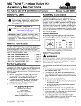
FIGURE 16. Fittings Installed on the Valve
High Flow Valve (P/N 063-0131-142)
FIGURE 17. Fittings Installed on the Valve
Fitting Part Number Port
Fitting - 7/8” JIC (M) to 7/8” SAE O-Ring (M) Straight Adapter 333-0012-246 P, T, EF
Fitting - 7/16” SAE O-Ring (M) to Male Diagnostic Nipple Hydraulic 333-0012-308 G1, G2
Fitting - 7/8” JIC (M) to 3/4” SAE O-Ring (M) 333-0012-110 CF, T1
Fitting - 3/4” SAE O-Ring (M) Plug 333-0012-211 T2
Fitting - 1/4” NPT Breather 333-0012-189 RV
Fitting Part Number Port
Fitting - 7/8” JIC (M) to 1-1/16” SAE O-Ring (M) Straight Adapter 333-0012-319 P, T, EF
Fitting - 7/16” SAE O-Ring (M) to Male Diagnostic Nipple Hydraulic 333-0012-308 G1, G2
Fitting - 7/8” JIC (M) to 7/8” SAE O-Ring (M) 333-0012-246 CF, T1
Fitting - 7/8” SAE O-Ring (M) Plug 333-0012-242 T2
Fitting - 1/4” NPT Breather 333-0012-189 RV
/