Thermo Fisher Scientific 1160 User manual
- Type
- User manual

The 220V option complies with 89/336/EEC directive for electromagnetic compatibility.
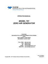
Model 1160
Instruction Manual
Zero Air Supply
Part Number 18665
11Feb2022

© 2007 Thermo Fisher Scientific Inc. All rights reserved.
Specifications, terms and pricing are subject to change. Not all products are available in all countries. Please
consult your local sales representative for details.
Thermo Fisher Scientific
Air Quality Instruments
27 Forge Parkway
Franklin, MA 02038
1-508-520-0430
www.thermo.com/aqi

Thermo Fisher Scientific WEEE Compliance
WEEE Compliance
This product is required to comply with the European Union’s Waste
Electrical & Electronic Equipment (WEEE) Directive 2002/96/EC. It is
marked with the following symbol:
Thermo Fisher Scientific has contracted with one or more
recycling/disposal companies in each EU Member State, and this product
should be disposed of or recycled through them. Further information on
Thermo Fisher Scientific’s compliance with these Directives, the recyclers
in your country, and information on Thermo Fisher Scientific products
which may assist the detection of substances subject to the RoHS Directive
are available at: www.thermo.com/WEEERoHS.


v
TABLE OF CONTENTS
CHAPTER 1 INTRODUCTION.........................................................................1-1
Basic Platform..................................................................................................................1-1
Add-Ons........................................................................................................................... 1-2
Performance Specifications ............................................................................................. 1-5
CHAPTER 2 INSTALLATION ..........................................................................2-1
Lifting .............................................................................................................................. 2-1
Unpacking........................................................................................................................ 2-1
Assembly.......................................................................................................................... 2-2
Input/Output Functions .................................................................................................... 2-3
Scrubber Installation ........................................................................................................ 2-4
CHAPTER 3 OPERATION ...............................................................................3-1
Front Panel Display and Controls.................................................................................... 3-1
Pressure................................................................................................................ 3-2
Converter Temperature ........................................................................................ 3-2
Status LEDs ......................................................................................................... 3-2
Converter Ready ...................................................................................... 3-2
Standby .................................................................................................... 3-2
Service Alarm .......................................................................................... 3-2
Mode Selection .................................................................................................... 3-3
Converter Temperature ........................................................................................ 3-5
Power-Up Sequence......................................................................................................... 3-6
CHAPTER 4 MAINTENANCE..........................................................................4-1
Spare Parts ....................................................................................................................... 4-1
Scrubbers ......................................................................................................................... 4-3
Compressor ......................................................................................................................4-4
Fan Filter.......................................................................................................................... 4-4
Fuse Replacement ............................................................................................................ 4-4
Service Alarm Battery ..................................................................................................... 4-4
Service Locations............................................................................................................. 4-5

vi
APPENDIX A WARRANTY.............................................................................A-1
APPENDIX B PUMP/COMPRESSOR MAINTENANCE..................................B-1
APPENDIX C SCHEMATICS ..........................................................................C-1
Power Supply Board ........................................................................................................C-2
Display Board ..................................................................................................................C-3
Rear Connector Interface .................................................................................................C-4
Instrument AC Power, 120 VAC, 50/60 Hz ....................................................................C-5
Instrument AC Power, 220 VAC, 50 Hz .........................................................................C-6
Instrument AC Power, 240 VAC, 60 Hz .........................................................................C-7
Instrument AC Power, 100 VAC, 50/60 Hz ....................................................................C-8

vii
LIST OF ILLUSTRATIONS
Figure Page
1-1 Model 1160 Components..................................................................................... 1-3
1-2 Model 1160 Flow Schematic ............................................................................... 1-4
2-1 Model 1160 Rear Panel........................................................................................ 2-2
2-2 Pin Out of Rear Panel Terminal Strip.................................................................. 2-3
2-3 Scrubber Base and Top Plates ............................................................................. 2-5
2-4 Scrubber Assembly Components......................................................................... 2-6
3-1 Front Panel Display ............................................................................................. 3-1
3-2 Display Board ...................................................................................................... 3-4
3-3 Power Board Component Footprint..................................................................... 3-5
4-1 Scrubber Parts List............................................................................................... 4-2


ix
LIST OF TABLES
Table Page
1-1 Pollutant, Removal Method, and Removal Component ...................................... 1-1
3-1 Mode Selections................................................................................................... 3-3
4-1 Recommended Spare Parts .................................................................................. 4-1


1-1
CHAPTER 1
INTRODUCTION
Thermo Scientific’s Model 1160 Zero Air Supply converts ambient air to pollutant-free
air. Table 1-1 describes the pollutants that can be removed, the method of removal, and
the removal component.
Table 1-1. Pollutant, Removal Method, and Removal Component
Pollutant/Contaminant
Method
Component
Water
Condensation
Cooling loop/coalescing filters
Adsorbent desiccant
Regenerative dryer
Membrane permeation
Membrane dryer
Absorption
Drierite scrubber
Oxides of Nitrogen (NO
x
)
Adsorption, absorption,
chemical reaction
Purafil scrubber
SO2
Adsorption
Charcoal scrubber
Ozone (O3)
Adsorption
Charcoal scrubber
CO
Oxidation to CO2
Catalytic Converter
Hydrocarbons (VOCs)
Oxidation
Catalytic Converter
Adsorption
Charcoal scrubber
BASIC PLATFORM
Although the Model 1160 can purge all the pollutants shown in Table 1-1, many
applications do not require the air system to eliminate the full range. Therefore, the
Model 1160 is designed as a basic platform to which a number of options can be added.
The exact configuration of each system depends upon the application and the pollutant(s)
to be eliminated. The basic Model 1160 platform consists of the following:
• Electronics. Control instrument power, front panel display and I/O.
• Cooling loop/coalescing filters. Remove water.
• Regulator. Controls output pressure.
• Single Scrubber. Choice of removing NOX (Oxides of Nitrogen) or CO2 or SO2
and O3.

Chapter 1 Introduction
1-2
ADD-ONS
Depending upon the application, the following items may be added to the basic platform:
• Internal Compressor. Depending on the model, the internal compressor
provides up to 20 LPM of flow at pressures up to 50 psi. If the internal
compressor is not purchased, an external compressor or a “house” air supply can
be connected to the inlet bulkhead on the rear panel. The inlet bulkhead connects
the air supply to the coalescing filters. If the Model 1160 utilizes an external
pump or air supply and has a regenerative dryer installed, the air supply should be
able to produce at least 30 LPM of flow at a pressure of at least 60 psi. At lower
pressures, the drying efficiency will be compromised. Inlet pressure must be
limited to 90 PSI when using an external air supply.
• Scrubbers. The Model 1160 can contain up to three scrubbing modules. When
multiple scrubbers are installed, they may be used in any combination to
simultaneously remove more than one pollutant, or multiple modules may be
filled with the same material to extend the time between service. Note. The
recommended order is, drierite, purafil, and charcoal. The following scrubbing
materials are available:
a) Charcoal: Removes ozone (O3), sulfur dioxide (SO2), and non-
methane hydrocarbons.
b) Purafil: Removes NOx
c) Drierite: Removes water vapor. It should be noted that this material is
not normally used without a regenerative dryer. Used alone it will
effectively reduce the amount of water vapor, but it may quickly
become saturated and increase the frequency of service.
• Dryers. If dry air is required, the Model 1160 may include either a membrane or
a regenerative dryer. For most applications, it is recommended that one of these
be used since the efficiency of adsorbents such as charcoal and Purafil may
decrease at high humidity levels.
Although the regenerative dryer provides a lower dew point than the membrane
dryer, it is more costly and requires higher airflow to operate. The membrane
dryer is suitable for many applications that do not require a dew point below 5°C.
The operation of the dryers is as follows:
a) Membrane: The membrane dryer uses non-porous, hollow fiber
membranes. Compressed air is conducted inside the membranes.
Water vapor molecules permeate the wall of the membrane, leaving
the oxygen and nitrogen molecules to exit the outlet as dry air. A
small amount of dry air is routed to the outside of the membrane fibers
to sweep away the permeated water vapor through a purge valve.

Chapter 1 Introduction
1-3
b) Regenerative: The regenerative, or heatless, air dryer consists of two
chambers filled with an adsorbent desiccant. One chamber dries the
gas stream while the other is regenerated using a small amount of the
dried air flowing as a countercurrent. The wet air is released as a
vapor through an exhaust port. The regenerative dryer can also be
used to remove CO2.
For applications using externally supplied air, the regenerative dryer
requires a minimum inlet pressure of 60 psi, and an inlet flow rate of at
least 30 LPM. The maximum inlet pressure is 90 psi and the
maximum flow rate is about 90 LPM. An outlet dew point of –30 °C
or greater may be achieved with the use of Drierite desiccant. The
by-pass consumes about 25 to 30% of the total available flow.
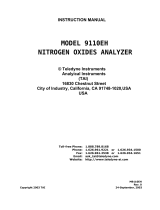
The components of the basic instrument and the options are shown in Figure 1-1.
Figure 1-1. Model 1160 Components

Chapter 1 Introduction
1-4
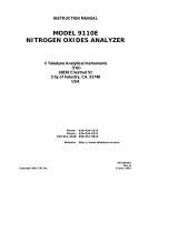
The flow through a fully equipped Model 1160 is shown in Figure 1-2. Ambient air is
drawn into the instrument by the internal compressor. It enters a loop where air from the
fan cools the air stream and condenses out water. The water condensate is removed by
the water coalescing filters, and ejected via drains in the rear panel. The membrane dryer
or heatless regenerative dryer further dries the air. The dry air is then routed to the
scrubbers, which remove a variety of pollutants. It then goes to the converter for removal
of CO and VOCs, before passing through a loop to cool the air to room temperature. It
then goes to the pressure regulator and out the rear panel to be used for instrument zero
air, or to provide clean diluent air for span gas systems.
Figure 1-2. Model 1160 Flow Schematic
Note: PN7075=Purafil, PN4157=Charcoal, PN6988=Drierite System. Check valve
opens at approximately 80 psi.

Chapter 1 Introduction
1-5
PERFORMANCE SPECIFICATIONS
Parameter Specification Comments
Maximum Capacity: 0.71 CFM (20 SLPM) @ 120 VAC, 60 Hz input, permeation dryer
0.53 CFM (15 SLPM) @ 120 VAC, 60 Hz input, regenerative dryer
Maximum Delivery Pressure: 50 PSIG (345 KPa) @ 120 VAC, 60 Hz input, permeation dryer
40 PSIG (275 KPa) @ 120 VAC, 60 Hz input, regenerative dryer
CO Oxidizing Efficiency: 99.998% *
CO Breakthrough undetectable Based on typical ambient air as input
HC Oxidizing Efficiency: 99.798% * Specified as methane
HC Breakthrough < 5-ppb output Based on typical ambient air as input
SO2 Breakthrough: < 0.5 PPB
NO2 Breakthrough: < 0.5 PPB
Dew Point Temperature (option): ≤ 5.0 °C Permeation method
≤ -30 °C Regenerative method
Ambient Operation temperature
Range: 15-35 °C
Storage Temperature Range: 0-40 °C
Input Power: 1300 VA Absolute maximum value,
Input voltage/ frequency dependent
Input Voltages / Frequency: 100 VAC, 60 Hz Japan
120 VAC, 60 Hz North/South America
240 VAC, 60 Hz North America
220 VAC, 50 Hz Europe/Asia
240 VAC, 50 Hz Asia/Africa/Oceania/United Kingdom
Ambient Environmental
Conditions: Indoor Use Std. Atmospheric Conditions.
Mounting: Bench Top Standard
Rack mount option 206
Dimensions: 16.90 W x 24.0 D x 9.20 H
(42.93 cm x 55.88 cm x 23.37 cm)
Weight: 85 lbs. (38.6 Kg) Fully Equipped
User Interface/Control: Output Pressure Front Panel LED Display (Default)
Reactor Temperature Front Panel LED Display (Pushbutton)
Compressor Stand-by J2 Header, Rear Panel, (Pin 7 to Ground)
Pressure Alarm J2 Header, Rear Panel, Passive Contacts
Temperature Alarm J2 Header, Rear Panel, Passive Contacts
Alarm Contact Rating: 0-24 Volts, 0.5 Amps

Chapter 1 Introduction
1-6
*Note: Oxidizing efficiencies are derived from empirical data established by the
Manufacturer. The test results are based on data collected using:
• Thermo Scientific’s Model 48C, CO Analyzer and a Certified instrument span gas
(3990 ppm CO, balance: Air) for Carbon Monoxide.
• Thermo Scientific’s Model 51C, Total Hydrocarbon Analyzer and a Certified
instrument span gas (59.1 ppm Methane, balance: Air) for Hydrocarbons.

2-1
CHAPTER 2
INSTALLATION
Installation of the Model 1160 zero air supply includes lifting and unpacking the
instrument, connecting the compressor, connecting the gas flow lines, and attachment to
suitable AC power.
LIFTING
A procedure appropriate to lifting a heavy object should be used when lifting the zero air
supply. This procedure consists of bending at the knees while keeping your back straight
and upright. The case should be grasped at the bottom, in the front and at the rear of the
unit. Do not attempt to lift by the cover or other external fittings. While one person may
lift the unit, it is desirable to have two persons lifting, one by grasping the bottom in the
front and the other by grasping the bottom in the rear.
UNPACKING
The Thermo Scientific Model 1160 Zero Air Supply is shipped in one container. If, upon
receipt, there is obvious damage to the shipping container, notify the carrier immediately
and hold for his inspection. The carrier, and not Thermo Fisher Scientific, is responsible
for any damage done during shipment.
To unpack the Model 1160 Zero Air Supply, follow the procedure outlined below:
1. Remove the Model 1160 from the shipping container and set on a table or
bench that allows easy access to both the front and rear of the instrument.
2. Remove the Model 1160 cover from the main frame of the unit, to expose
the internal components of the instrument.
3. Check for possible damage during shipment.
4. Reinstall the cover.
5. Check for possible damage during shipment.

Chapter 2 Installation
2-2
ASSEMBLY
1. If an external compressor will be used to supply the air, connect it to the
“inlet” bulkhead with ¼" O.D. line.
IMPORTANT: Applications using an external air source must pressure regulate
to 70 PSI or less, and must pre-condition the inlet air in accordance with ISO
standard 8573-1. A minimum air quality level of Class 2 for hydrocarbons (oils)
and Class 1 for particulates (dust, rust, etc.) is required. Failure to meet this
requirement can potentially degrade the performance of certain components in the
zero air supply.
2. Using 1/4" Teflon, or pre-cleaned metal tubing, connect the outlet of the
Model 1160 to the device requiring “zero air” (See Figure 2-1).
3. Remove protective caps that cover the drain ports in the rear panel. If
desired, connect a drain line to these ports using 1/8" compression fittings or
soft tubing such as silicone rubber.
4. Fill and re-install the internal scrubbers and check that the hold-down
screws are securely fastened. (Detailed instructions are presented at the end
of this chapter.)
5. Check the voltage label to verify that it matches the local power and plug
the AC line cord into an appropriate power source.
86P702
Figure 2-1. Model 1160 Rear Panel

Chapter 2 Installation
2-3
INPUT / OUTPUT FUNCTIONS
The 1160, rear panel includes one set of eight I/O pins that can be used to monitor and
control the unit’s operation. The pin- assignments for the connector are shown in Figure
2-2.
As indicated, pins 1 and 2 are used for a general service alarm, pins 3 and 4 are used by
the low-temperature alarm, and pins 5 and 6 are used by the low-pressure alarm. The
pressure alarm is triggered in the event of a pump failure and the temperature alarm is
triggered in the event of heater failure. In each case, an alarm condition is indicated by
continuity between the two pins. For example, if the heater circuit fails, it will create a
low-temperature condition and a relay will close connecting pin 3 to pin 4.
The service alarm on pins 1 and 2 is intended as reminder to change the adsorbent or
scrubber canisters on a routine basis. The alarm triggered on the basis total elapsed run-
time since last reset. As described in Chapter 3, the service alarm timing may be
adjusted, or the alarm can be turned off, by selecting a jumper on the display board
located on the inside surface of the front panel. The timer-reset button is also located on
the display board.
In addition to the alarm outputs, the rear panel connector also has one input and a ground.
By connecting pin 7 to instrument ground at pin 8, a data logger or other control device
can switch the 1160 to stand-by mode. In stand-by mode the internal pump is switched
off. Stand-by is used to reduce pump wear and prolong adsorbent media life by turning
the pump off when zero-air is not needed.
Figure 2-2. Pin Out of Rear Terminal Strip

Chapter 2 Installation
2-4
SCRUBBER INSTALLATION
The 1160 are shipped with the adsorbent scrubber systems empty. Before turning the
instrument on, make sure that the canisters contain fresh packing. Please refer to Figures
2-3, 2-4 and 4-1 while reviewing the following procedure.
1. Loosen the hold down screw, swing the handle aside and remove the top plate.
2. Insure that both felt-pad filters are flat against the bottom of the plastic
canister.
3. Fill both the inner and outer cylinders of the canister to approximately ¼” of
the top with the proper packing. Do not over-fill or the cover may not seat
properly.
4. Replace the top plate, insuring that the O-ring is properly seated. Note that
there are two O-rings in the base plate and one in the scrubber cap, as shown
in Figure 2-3. The O-rings can be identified by comparison with the full size,
or 1:1, drawing included in Figure 2-4.
5. Re-seat the canisters, being sure that the O-rings are properly seated, and then
swing the handle back up into position.
6. Tighten the hold down screw “finger-tight.” Then, use a 3/8” open-end
wrench to turn the screw approximately ¾ turn more. Do not over-tighten.
Page is loading ...
Page is loading ...
Page is loading ...
Page is loading ...
Page is loading ...
Page is loading ...
Page is loading ...
Page is loading ...
Page is loading ...
Page is loading ...
Page is loading ...
Page is loading ...
Page is loading ...
Page is loading ...
Page is loading ...
Page is loading ...
Page is loading ...
Page is loading ...
Page is loading ...
Page is loading ...
Page is loading ...
Page is loading ...
Page is loading ...
Page is loading ...
Page is loading ...
Page is loading ...
Page is loading ...
Page is loading ...
Page is loading ...
Page is loading ...
Page is loading ...
Page is loading ...
-
 1
1
-
 2
2
-
 3
3
-
 4
4
-
 5
5
-
 6
6
-
 7
7
-
 8
8
-
 9
9
-
 10
10
-
 11
11
-
 12
12
-
 13
13
-
 14
14
-
 15
15
-
 16
16
-
 17
17
-
 18
18
-
 19
19
-
 20
20
-
 21
21
-
 22
22
-
 23
23
-
 24
24
-
 25
25
-
 26
26
-
 27
27
-
 28
28
-
 29
29
-
 30
30
-
 31
31
-
 32
32
-
 33
33
-
 34
34
-
 35
35
-
 36
36
-
 37
37
-
 38
38
-
 39
39
-
 40
40
-
 41
41
-
 42
42
-
 43
43
-
 44
44
-
 45
45
-
 46
46
-
 47
47
-
 48
48
-
 49
49
-
 50
50
-
 51
51
-
 52
52


Thermo Fisher Scientific 1160 User manual
- Type
- User manual
Ask a question and I''ll find the answer in the document
Finding information in a document is now easier with AI
Related papers
-
 Thermo Fisher Scientific A/D Converter 1.0 User guide
-
 Thermo Fisher Scientific 43iQ Sulfur Dioxide Analyzer User manual
-
 Thermo Fisher Scientific 450iQ Hydrogen Sulfide and Sulfur Dioxide Analyzer User manual
-
 Thermo Fisher Scientific 48iQTL Trace Level Carbon Monoxide Analyzer User manual
-
 Thermo Fisher Scientific 42iQ User manual
-
 Thermo Fisher Scientific PDM3700 Charger Update Owner's manual
-
 Thermo Fisher Scientific 42i User manual
-
 Thermo Fisher Scientific 43i User manual
-
 Thermo Fisher Scientific 43i-HL User manual
-
 Thermo Fisher Scientific 111 Zero Air Supply User manual


Other documents
-
 Teledyne Portable Generator 701 User manual
-
Teledyne API T701 User manual
-
 Teledyne 751H User manual
-
-
 Teledyne 701H User manual
-
-
-
 Teledyne 9110EH User manual
-
 Teledyne 9110E User manual
-


