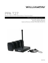
Williams Sound PPA R38 User manual

Type
User manual

This manual is also suitable for

PPA T45NET / PPA T45
Personal PA® DSP FM Wideband Transmitter
USER Manual
Transmitter Models PPA T45NET and PPA T45
Optional Receiver Models PPA R38, PPA R37, PPA R35-8, PPA R1600
MAN 176C
PRINTED IN THE U.S.A.
2
Personal PA® DSP FM Wideband Transmitter
Table of Contents
System Connection Overview 6
Figure 1: Typical System Example 6
Wiring and Connections 7
Power Supply Connection 7
Ethernet Connection 7
Audio Source Connections 7
Figure 2: PPA T45NET Rear View 7
Multi–Channel Sources 8
Selecting an Audio source Appropriate for Hearing Impaired Listeners 8
Figure 3: Audio Source Connectors 8
Avoiding Hum in the Audio (as a Result of a Ground Loop) 9
Figure 4: Connecting to a Balance/Unbalanced Line 9
Installing the ANT 025 Whip Antenna 9
Figure 5: Installing the ANT 025 Antenna (rear view) 9
Connecting the T45 to other Devices 10
Figure 6: T45 Typical Connections 10
Controls & Features 11
Figure 7: PPA T45 Front View 11
Power Button 11
OLED Display 11
Audio Input Level Indicator 11
Input Overload Indication 11
RF Indicator (On Air) 11
Hot Buttons / Menu Controls 11
Headphone Jack 12
Main Info Screen and Screen Navigation 12
Lock/Unlock Settings 12
Figure 8: Main Info Screen 12
Figure 9: Navigating the Menu 12
Quick Setup Instructions 13
Front Screen Menu Tree (Quick Reference) 14
Figure 10: Front-screen Menu Tree 14
Figure 11: Front-screen Menu Tree (continued) 15
Figure 12: Front-screen Menu Tree (continued) 16
Front Screen Menu Tree (Detailed Instructions) 16
1. AUDIO SETTINGS 16
1a. Audio Presets 16
Figure 13: Audio Preset Conguration Table 16
High Pass Filter 17
Low Pass Filter 17
3
Personal PA® DSP FM Wideband Transmitter
Compression 17
1b. Audio Source 18
1c. Audio Input Gain 19
1d. Headphone Source 19
1e. Headphone Volume 19
2. RF SETTINGS 20
2a. Channel (or Frequency) 20
Figure 14: Channel/Frequency Selection Chart 20
2b. RF Output Power 20
2c. RF Time-Out 21
3. PREFERENCES 21
3a. Display Mode 21
3b. Channel Mode 22
3c. Screen Time-Out 22
3d. User-Entered Transmitter Description 22
3e. Restore Defaults 23
4. ADD-ON MODULE (PPA T45NET only) 24
4a. Status 24
4b. Network Settings 24
4c. Admin 25
Network Setup for Hard-wired Ethernet Devices (Laptop or Desktop PC) 26
Figure 15: Williams Sound Device Discoverer Tool (optional) 27
Network Setup for Wireless Devices (iPad, Android Tablet, or Smart Phone) 28
Figure 16: Williams Sound Device Discoverer Tool 28
Web Control Interface 30
Figure 17: Main Login Page and Ethernet Communication Status 30
Figure 18: Home Page 31
Figure 19: Audio Settings Page 32
Figure 20: RF Settings Page 33
Figure 21: Network Settings Page 34
Figure 22: Administration Page 34
Receiver Safety Information 35
Recycling Instructions 35
Wideband FM Receivers (Model Selection is Optional) 36
Receiver Model PPA R38 36
Figure 23: PPA R38 Controls and Display 36
Operating the receiver 36
Wideband FM Receivers (continued) 37
Receiver Model PPA R37 37
4
Personal PA® DSP FM Wideband Transmitter
Operating the PPA R37 Receiver 37
Figure 25: Battery and channel selections 37
Figure 24: PPA R37 controls 37
LED Flash Codes 37
Receiver Model PPA R35-8 38
Operating the PPA R35-8 Receiver 38
Connecting Earphones/Headphones 38
Battery Installation (All Receiver Models) 38
Figure 26: PPA R35-8 controls 38
Belt Clip Installation (All Receiver Models) 39
Earpad Cleaning for Earphones and Headphones 39
Figure 27: Belt Clip Installation and Removal 39
Suggestions For Receiver Management 40
Receiver Battery Information (All Receiver Models) 40
Battery Charger Information 40
Troubleshooting 41
The T45 “RF” (On Air) Indicator is not on 41
No Audio heard in Phones jack 41
Noise or Distortion in the Audio 41
Noise in audio “grows” when program is silent 41
Reception difculties 41
No Reception 41
Insufcient range, good reception near transmitter, poor at a distance 41
Users must turn receiver volume controls way up (to 4 or 5) to get enough volume 42
Users complain of too much noise during soft audio. Dynamic range of music reduced too greatly. 42
Buzz in other equipment when transmitter is on or off 42
Buzz or other noise in equipment only when transmitter is on 42
Remote Control is not working over the hardwired Ethernet network 43
Remote Control is not working over Wi-Fi 44
System Specications PPA T45, PPA T45NET Transmitters 45
System Specications PPA T45, PPA T45NET Transmitters (continued) 46
System Specications PPA R38 Receiver 47
System Specications PPA R35-8 Receiver 48
System Specications PPA R37 Receiver 49
Lifetime PLUS Limited Warranty 50
5
Personal PA® DSP FM Wideband Transmitter
This page intentionally left blank
6
Personal PA® DSP FM Wideband Transmitter
LOUDSPEAKER
LINE-LEVEL
OUTPUT
SOUND SYSTEM/
AMPLIFIER MICROPHONE
PPA T45 TRANSMITTER
FM RECEIVERS
A408
ROUTER
IPAD, TABLET OR PHONE
WITH WI-FI
FM
WI-FI
DESKTOP (OR LAPTOP) COMPUTER
(HARD-WIRED TO ROUTER)
LINE-LEVEL
INPUT
AUDIO/LISTENING SIDE CONTROL SIDE (PPA T45NET only)
ETHERNET (PPA T45NET only)
ETHERNET
System Connection Overview
The PPA T45 is an FM Wide-Band transmitter operating in the 72-76MHz bandwidth. Compatible Williams Sound receivers
include PPA R38, PPA R37, PPA R35-8 body packs and the PPA R1600 remote speaker.
Developed for hearing assistance in places of public access, the PPA T45 is designed for those who need help overcoming
background noise, reverberation, or distance from the sound source. It includes a complete audio processor optimized for the
needs of hearing impaired persons and is easily integrated with your existing sound system. The PPA T45 can also be used with a
microphone as a stand-alone system.
Your PPA T45 transmitter operates just like an FM radio station. The transmitter takes audio directly from a microphone or sound
system. This audio is then broadcast over an FM radio signal. FM radios can be worn by listeners or an AC powered amplied
speaker with built in receiver can be utilized as needed. The broadcast can be received up to 1000 ft from the transmitter *. This
allows listeners to sit anywhere in the area and listen to the broadcast at the volume level they need without disturbing others
around them.
Two models are available - one with Ethernet control (PPA T45NET) and one without Ethernet control (PPA T45). Ethernet control
allows the transmitter settings to be changed over a network with hard-wired or wireless devices (Figure 1).
*Range is dependent on the environment.
Figure 1: Typical System Example
7
Personal PA® DSP FM Wideband Transmitter
Wiring and Connections
24VDC 0.75A
williamssound.com
Line / Mic In
Analog
Audio
Digital
Audio
Line Out AES / EBU In S/PDIF In RF 75 Ω Ant Ethernet
bal
unbal
phantom
T45 Rear
A401
ANALOG
LINE/MIC INPUT
ACCEPTS BALANCED
OR UNBALANCED
1/4” PLUG or XLR
RCA LINE OUTPUT
FOR MONITORING
OR RECORDING
DIGITAL INPUT
ACCEPTS AES
OR EBU DIGITAL
AUDIO XLR PLUG
RCA DIGITAL AUDIO
INPUT FOR
COAXIAL/DIGITAL
AUDIO
RF OUTPUT
FOR REMOTE
ANTENNA
CONNECTION
ETHERNET JACK
WITH LINK AND
ACTIVITY LED’S
(PPA T45NET Only)
POWER SUPPLY
JACK
Power Supply Connection
Connect the TFP 048 power supply to the Power Supply Jack located on the rear of the PPA T45 transmitter (Figure 2).
Ethernet Connection
If connecting to a network, or connecting directly to a PC, a Standard or Crossover Ethernet cable may be used. The PPA
T45NET auto-senses the connection and congures itself for the Ethernet cable type being used.
Audio Source Connections
The T45 transmitter will accept the following audio sources:
1. Balanced Microphone on a 3-pin (XLR) connector without phantom power.
2. Balanced Microphone with 12 volt phantom power (DIN 45596) on a 3-pin (XLR) connector.
3. Balanced/Unbalanced microphone with or without phantom power on 1/4 inch (TRS) jack
4. Balanced/Unbalanced Line on a 3-pin (XLR) connector.
5. Balanced/Unbalanced Line on 1/4 inch (TRS) jack.
6. Digital Audio (AES/EBU) on a 3-pin (XLR) connector.
7. Digital Audio (S/PDIF) on an RCA jack.
WARNING:
The T45 is not designed to accept 70 volt speaker signals! This may result in damage to your system. The
sound source should come directly from the system mixer or digital source as a low-level or unprocessed
signal.
IMPORTANT: When a suitable audio source has been determined, you MUST congure the audio source in the menu
of the T45 before plugging that source in.
NOTE: FCC regulations, section 15.21, requires the user to comply with the rules of transmitter operation. Any
changes or modications made by the user not expressly approved for compliance may result in the loss of all
privileges and authority to operate the equipment.
Figure 2: PPA T45NET Rear View
8
Personal PA® DSP FM Wideband Transmitter
BALANCED LINE USING 1/4" CONNECTOR
IN PHASE
A106
UNBALANCED LINE USING 1/4" CONNECTOR
A107
4.7 K
4.7 K
SOURCE A
SOURCE B
CONNECTING TO A MULTI-CHANNEL OR STEREO SOURCE
A109
BALANCED LINE USING 3–PIN CONNECTOR
IN PHASE
1 2
3
3 PIN CONNECTOR
A108
IN PHASE
FROM MICROPHONE
1 2
3
3 PIN CONNECTOR
LOW IMPEDANCE MICROPHONE
A104
UNBALANCED LINE USING 3–PIN CONNECTOR
1 2
3
3 PIN CONNECTOR
A105
Figure 3: Audio Source Connectors
Multi–Channel Sources
By constructing a simple resistive mixer, stereo (or 3 channel) sources can be connected to the T45. Additional channels can be
accommodated by adding a resistor for each source. Necessary resistors can be obtained from Williams Sound (Part Number
RFC 472) or from any local electronics parts supplier. See Figure 3.
Selecting an Audio source Appropriate for Hearing Impaired Listeners
If the T45 is going to be used specically for the accommodation of hearing impaired listeners, we recommend following these
general guidelines:
The PPA T45 transmits audio with excellent delity. Therefore, the audio source signal should be of the highest audio quality and
not subject to a compressor, limiter, reverberation, or other signal processing equipment. The T45 has a very effective DSP audio
processor. If compression is desired in the audio, refer to the “Compression” section under “Audio Settings - 1a. Audio Presets”
for available settings. Excessive compression is not helpful to the hearing impaired and can contribute to excessive noise in the
receiver outputs.
The T45 audio source signal is usually connected to a mixer’s “line output” signal which is behind the mixer’s parametric equalizers
but ahead of any equalization used for house loudspeakers.
If audio delay is available for use in large auditoriums, it’s usually best to use it. Because radio signals travel faster than sound,
delaying the transmitted audio so that an average listener (in the middle of the listening area) hears the transmitted audio a few
milliseconds after audio from the main sound reinforcement system speaker is helpful. This will also help audience members who
lip read.
9
Personal PA® DSP FM Wideband Transmitter
Avoiding Hum in the Audio (as a Result of a Ground Loop)
A hum created by a ground loop can often be eliminated by connecting a capacitor in series with the audio line shield to the
transmitter’s ground. This method also maintains good RF shielding. Determining the effectiveness of this method for your
installation usually requires some experimentation. Necessary capacitors can be obtained from Williams Sound or from any
electronic parts supplier. See Figure 4.
Figure 4: Connecting to a Balance/Unbalanced Line
IN PHASE
1 2
3
3-PIN
CONNECTOR
BREAKING A GROUND LOOP WHEN
CONNECTING TO A UNBALANCED LINE
BREAKING A GROUND LOOP WHEN
CONNECTING TO A BALANCED LINE
.01 uF CERAMIC DISC
CAPACITOR .01 uF CERAMIC
DISC CAPACITOR
A110
Installing the ANT 025 Whip Antenna
Gently thread the ANT 025 onto the stud recessed in the hole on the top of the transmitter. See Figure 5.
Figure 5: Installing the ANT 025 Antenna (rear view)
ANT 025 ANTENNA
(INCLUDED)
REMOTE ANTENNA
COAXIAL JACK
FOR
75 Ohm ANTENNAS
(See note below)
24VDC 0.75A
williamssound.com
Line / Mic In
Analog
Audio
Digital
Audio
Line Out AES / EBU In S/PDIF In RF 75 Ω Ant Ethernet
bal
unbal
phantom
NOTE: If the T45 is going to be rack mounted, you will not be able to install the ANT 025 whip antenna. For rack mounting,
consider installing a remote antenna like the ANT 005 or ANT 024 - these antennas require using the Remote Antenna
Coaxial Jack (above) and a long length of terminated coaxial cable. Another option is to mount the antenna on the
rack itself - consider the ANT 029 which includes a 1RU bracket and a 3ft terminated coaxial cable. For a full list of
antenna options, please go to our website www.williamssound.com and view the Antenna Application Guide under
“Products - Accessories - Antennas”.
10
Personal PA® DSP FM Wideband Transmitter
Figure 6: T45 Typical Connections
A407
24VDC 0.75A
williamssound.com
Line / Mic In
Analog
Audio
Digital
Audio
Line Out AES / EBU In S/PDIF In RF 75 Ω Ant Ethernet
bal
unbal
phantom
ANALOG AUDIO
LINE OUT (RCA)
ANALOG
LINE/MIC INPUT
(XLR OR 1/4”)
BALANCED,
UNBALANCED,
OR PHANTOM.
DIGITAL
LINE
INPUT
(RCA)
REMOTE
ANTENNA
CONNECTION
(RG-6 QS,F-CONN)
PPA T45
ANALOG MIXER OR AUDIO SYSTEM
AUDIO LINE IN (RCA)
ROUTER
ANALOG LINE
OUTPUT
(1/4” or XLR)
DIGITAL
LINE
INPUT
(XLR)
AES or EBU.
PPA T45NET ONLY
DEVICE OR MIXER WITH S/PDIF OUTPUT
DIGITAL LINE OUT (RCA)
DIGITAL MIXER
REMOTE
ANTENNA
STANDARD CAT5 ETHERNET CABLE (RJ-45)
MICROPHONE
(CONDENSER
OR OTHER)
ANALOG MIXER
DIGITAL LINE
OUTPUT
(XLR)
AES or EBU.
COMPUTER
OR
ETHERNET
SWITCH
INTERNET
MODEM
STANDARD
CAT5
ETHERNET
CABLES
(RJ-45)
TO AC
POWER
SOURCE
STANDARD CAT5 ETHERNET CABLE (RJ-45)
LAPTOP (OR DESKTOP)
COMPUTER
SUPPLIED
ANTENNA
EITHER
BUT
NOT
BOTH
Connecting the T45 to other Devices
The Analog LINE/MIC Input jack can be used with standard pro audio electronics such as standard pro audio line level,
condenser microphones up to 15v or an analog line output from a mixer. The combination jack accepts either XLR or 1/4” (TRS).
This source must be congured in the menu before plugging the source into the jack.
The RCA Audio Line Output jack can be used for monitoring, recording, or routing processed audio to another sound system.
The XLR Digital Line Input can be used with the output of a digital mixer or digital audio source. The processors inside the T45
convert the digital bitstream into usable audio.
The RCA S/PDIF Digital Line Input jack can be used with a device that has an RCA Digital Audio Out (also referred to as “Coaxial
Digital Audio” from consumer electronic devices. The processors inside the T45 convert the digital bitstream into usable audio.
The Remote Antenna Connection can be used to connect a remote antenna to the T45 when the whip antenna won’t be used
(as in the case of rack-mounting). See the Williams Sound Antenna Guide for a full range of antenna and mounting options (see
Figure 5).
The Ethernet Jack (PPA T45NET only) can be used to connect the T45NET to either (1) a local network or (2) directly to a single
computer. Both options can use either a standard Ethernet cable or a crossover cable. A crossover cable can be used, but is not
required to connect the T45 directly to a computer, because an internal MUX senses the device that is connected and crosses the
pins automatically.
11
Personal PA® DSP FM Wideband Transmitter
Power Button
Latching push-button switch turns the transmitter on or off. The desktop power supply provides power to the unit at all times.
(Figure 7)
OLED Display
This shows current operation settings and is also used with the menu control buttons for conguring the T45. Each time the power
of the unit is turned on, the OLED Display shows a “Williams Sound” start-up screen (Figure 8). After seven seconds, the “RF”
(On-Air) LED will illuminate and the default Main Info Screen screen will be displayed. The T45 is now fully operational. If the “RF”
(On-Air) indicator does not illuminate, check the RF settings to make sure RF is not set to “RF OFF”. Make sure the power supply
is properly installed, and the power button is in the “on” position. (Figure 7)
(NOTE: If the transmitter is not fully functional, and the internal tests fail, the transmitter will attempt to auto-recover by rebooting
itself.)
Audio Input Level Indicator
The bar graph indicator shows audio level in 3dB steps at the input of the audio level processing circuit. The indicator is peak
responding and is calibrated so that optimum level is reached when the 0dB LED lights up often and the +9dB only lights
occasionally. Use the Audio Level settings in the menu to set the audio levels. (Figure 7)
Input Overload Indication
The OLED Display shows an overload warning screen each time the audio signal exceeds the capacity of the input circuit. Either
(1) the source of the audio coming in to the T45 needs to be adjusted to correct this or (2) the Audio Input Gain needs to be
adjusted. (Figure 7)
RF Indicator (On Air)
Indicates when radio frequency is transmitting. (Figure 7)
Hot Buttons / Menu Controls
While the transmitter is displaying the Main Info Screen (Figure 8), the Up^” and Downv” buttons adjust the Audio Input
Gain; while the Left<” and Right>” buttons change the Channel. This immediate adjustment capability is referred to as “Hot
Buttons”.
The Menu button is a Enter/Exit menu function only. It does not “select” anything within the menu. It allows the user to quickly
return to the Main Info Screen from any place in the menu.
Figure 7: PPA T45 Front View
Controls & Features
POWER
BUTTON
(BACKLIT WHEN
UNIT IS ON)
RF
INDICATOR
(ON-AIR)
AUDIO
INPUT
LEVEL
INDICATORS
MENU BACK BUTTON
AND CHANNEL(-)
HOT BUTTON
MENU UP BUTTON
AND AUDIO INPUT
GAIN ADJUST(+)
HOT BUTTON
MAIN
MENU
BUTTON
OLED
DISPLAY
HEADPHONE
JACK
A405
MENU DOWN BUTTON
AND AUDIO INPUT
GAIN ADJUST(-)
HOT BUTTON
MENU FORWARD BUTTON
AND CHANNEL(+)
HOT BUTTON
12
Personal PA® DSP FM Wideband Transmitter
While the transmitter is displaying the Menu on the screen:
The Up^” button navigates upward in the menu or changes a setting. (Figure 9)
The Down “v” button navigates downward in the menu or changes a setting. (Figure 9)
The Left “<” button backs out of the menu one step at a time (see the menu tree). (Figure 9)
The Right “>” button navigates forward in the menu (see the menu tree) or selects a setting. When entering a Description, IP
Address, or Subnet Mask for the Transmitter (see the menu tree) this button advances to the next character. (Figure 9)
Headphone Jack
A headset plugged into the headphone jack allows monitoring either the audio input before it is processed and transmitted by
the T45 (Analog Sources only) or the T45 audio output after it gets processed. By default, the headphone jack audio is set for
“TRANSMITTED AUDIO”. The Menu also allows the listener to select “INPUT AUDIO”. When monitoring a digital input, the only
option available will be “TRANSMITTED AUDIO”, since the digital source cannot be listened to directly, it must be converted to
analog audio rst (Figure 7).
Main Info Screen and Screen Navigation
The Main Info Screen will show the following information: Operating Frequency/Channel, Device Description (if entered, otherwise
blank), RF Power Level, Network Link (PPA T45NET only), Audio Source, Audio Application Preset, Audio Input Gain Setting,
and Locked . The lock symbol indicates that the front panel buttons are locked, which prevents any functions from being
accidentally changed. If the front panel (menu) has been locked the display will show the lock symbol, otherwise this area will be
blank. (Figure 8)
If the T45NET is connected to a network or a PC, the network link will be displayed as shown in Figure 8. If the T45NET is not
connected, the network symbol will have an “X” through it (not shown).
Lock/Unlock Settings
To lock or unlock the front panel buttons, press and hold the Left “<” and Right “>” buttons together on the front of the T45 for 3
seconds. Three dashes will appear in the area where the lock symbol is shown (below), then disappear. When the last dash has
disappeared, a pop-up screen will appear indicating the settings have been locked (or unlocked) and the buttons can be released.
Figure 8: Main Info Screen
FREQUENCY (OR CH)
CHANNEL (OR FREQ)
USER-ENTERED
TRANSMITTER
DESCRIPTION
(BLANK IF
NOT ENTERED)
RF
POWER
LEVEL
NETWORK
LINK
(CONNECTED)
SETTINGS
LOCKED
ADD-ON MODULE INFO
(TWO LINES)
AUDIO SOURCE SELECTED
AUDIO PRESET SELECTED
AUDIO INPUT GAIN LEVEL SELECTED
A403
While navigating through the menu, caret symbols (<,>,^,v) will show up, indicating that parts of the menu exist “off-screen” to the
left, right, above or below. (Figure 9)
Figure 9: Navigating the Menu
MENU TREE EXISTS
TO THE LEFT
SELECTION BOX
MENU TREE EXISTS
TO THE RIGHT
A403
MENU / SUBMENU TITLE
MENU TREE EXISTS ABOVE / BELOW
13
Personal PA® DSP FM Wideband Transmitter
Quick Setup Instructions
1. Position the PPA T45 transmitter near the sound system or mixer from which it will receive audio. It should be free from metallic
objects that might interfere with the antenna signal.
2. If the transmitter is free-standing (not rack-mounted), install the ANT 025 whip antenna. Gently thread the ANT 025 onto
the stud recessed in the hole on the top of the transmitter (Figure 2) and extend it all the way. The transmitter can be rack-
mounted (1RU) with the optional RPK 005 Rack Mount Kit - in this case the whip antenna cannot be used; instead use the rear
“RF 75Ω ANT” coaxial jack for remote antenna mounting with a coaxial cable (Figure 5).
3. Connect the power supply to the Power Supply connector (Figure 2, page 5) located on the back of the T45. Press in the
power button on the front of the T45. The power button should light up, and the “RF” green LED indicator should illuminate. If
not, go back and check the power connections.
4. Choose and congure the audio source. The audio source must be congured in the menu before plugging the source
into the jack. Push the Menu button and push the “>” button once to display “AUDIO SOURCE” on the screen. Push the “>”
button to access the audio sources. Using the “^” or “v” menu buttons (Figure 2), choose between “ANALOG LINE IN”, “MIC”,
“PHANTOM MIC +12V”, “DIGITAL AES/EBU”, or “DIGITAL S/PDIF”. When the desired audio source is displayed, it is active, so
press the Menu button to exit the menu (Figure 7).
5. Push the power button to turn the unit off. (Figure 7)
6. Connect the audio source to the audio input jack on the rear of the T45 (the jack that was chosen in step 4). (Figures 2, 6)
7. Push the power button to turn the unit on. (Figure 7)
8. With the audio source playing, adjust the Audio Level on the T45 so that the green “0 dB” LED generally lights and the red “+9
dB” LED lights occasionally. To do this, use the Hot Buttons while on the main info screen. Press the “^” button to increase the
audio level in 1.0 dB steps, or press the “v” button to decrease the audio level in 1.0 dB steps.
9. Select an Audio Preset. The T45 has three pre-congured Audio Presets to choose from: Hearing Assist, Music, and Voice. A
Custom preset is also available. The performance of the T45 is optimized for each of the pre-congured Audio Presets. Using
the menu and control buttons on the front of the T45 (Figure 7), push the Menu button, the display will change to show “Audio
Settings”. Use the forward “>” button to display “Audio Source” in the selection box. Push the down “v” button twice to show
“Audio Presets”. Now press the “>” button to display the list of Presets. Use the “^” and “v” buttons to alternate between
“Hearing Assist”, “Music”, “Voice” and “Custom” selections. When the desired Audio Preset is displayed, it is active, so press
the Menu button to exit the menu, or, if “Custom” is desired, push the “>” button to enter the custom settings.
10. Set the Transmitter Channel. The T45 is shipped from the factory with the channel/frequency set to Ch.1 (72.1 MHz). To change the
channel/frequency, while on the main info screen, use the hot buttons “<” and “>” to change channels. (Figure 7)
11. Listen with an FM receiver (see compatible Williams Sound receivers towards the back of this manual). Install the batteries,
plug in the earphone, turn on the receiver, choose the correct channel and walk around the listening area. The signal should be
clear and quite loud when the volume is turned up.
12. (T45NET only) Connect a CAT5e Ethernet cable from your local area network, wi- router, or PC to the connector on the
T45NET labelled “Ethernet”.
13. (T45NET only) Once the T45 detects an active network is present, the “X” will disappear from the computer icon on the main
info screen, indicating that it has connected to the network. The main info screen will display the text “IP:\”, where the last
character “\” will spin, while the T45 is acquiring a DHCP address. Once acquired, (usually takes less than a minute), the T45’s
IP address will be displayed in the “Add-on module” part of the Main Info Screen. (Figure 8)
14. (T45NET only) Open a web browser (i.e. Internet Explorer, Mozilla Firefox, Google Chrome, Safari, etc.) on a computer or
mobile device that is also connected to the same local network as the T45.
15. (T45NET only) In the address bar of the browser, type in the IP address that is shown on the front of the T45NET’s main
info screen, and push the enter key on the keyboard. (Note: it is not necessary to type “http://” or “www.” preceding the IP
address, just the characters following “IP:”, including the periods)
16. (T45NET only) The browser will open the T45NET’s web page, displaying a “Log In” button (Figure 17). Click the log-in
button and enter the user name “admin” and the default password “admin”.
17. (T45NET only) The web browser will now show the T45NET’s Home Page (Figure 18), which shows the current T45NET
status info. The tabs at the top navigate to different pages that allow adjustment of the T45NET’s settings.
IMPORTANT: The FM receiver being used will need to be on the same channel/frequency as the T45 transmitter.
14
Personal PA® DSP FM Wideband Transmitter
AUDIO SETTINGS
AUDIO PRESET
AUDIO INPUT GAIN
VOICE
MUSIC
HEARING ASSIST
CUSTOM
ANALOG LINE IN
MIC
PHANTOM MIC (+12v)
DIGITAL AES/EBU
DIGITAL S/PDIF
400 HZ TEST TONE
0dB to -50dB by 1dB
RF SETTINGS
HEADPHONE SOURCE
HEADPHONE VOLUME
INPUT AUDIO
TRANSMITTED AUDIO
0dB to -40dB by 2dB
AUDIO SOURCE
HIGH PASS FILTER 31 - 630 HZ
LOW PASS FILTER
COMPRESSION
3.5 - 16 KHZ
1:1, 1.5:1, 2:1
MAIN INFO SCREEN
Figure 10: Front-screen Menu Tree
Front Screen Menu Tree (Quick Reference)
The default “MAIN INFO SCREEN” shows important overall system settings (see Figure 8). The menu screens are used to
congure the T45 (Figures 10,11,12). To enter the menu, push the “Menu” button. Then use the Forward “>” and Down “v”
buttons to navigate deeper into the menu. When a setting is reached, the display will change to show an up and down caret
(“^”,”v”) around the setting. Use the Up “^” and Down “v” buttons to change the setting. Note that nearly all settings change live,
they do not need to be “selected” with another button. The setting displayed in the selection box is the one that is active. After a
period with no button presses, the OLED will return to the Main Info Screen, then display a screen saver, then go blank. When the
display is blank, and the “RF” indicator is lit, the transmitter is still broadcasting. If audio is present the audio input level LED’s will
pulse to the level of the audio. Pressing any button will restore the Main Info Screen and restart the screensaver/auto-off timer.
15
Personal PA® DSP FM Wideband Transmitter
RF SETTINGS RF CHANNEL
RF OUTPUT POWER
CH 1 - CH 17
FULL
RF TIME-OUT
DISPLAY MODE
CHANNEL MODE
SCREEN TIME-OUT
PREFERENCES
DESCRIPTION SECOND CHARACTER LAST CHARACTER]
A406
Scroll up/down A to Z Scroll up/down A to Z
MEDIUM
LOW
OFF
30 MIN
4 HRS
ALWAYS ON
FREQUENCY
CHANNEL NUMBER
17-CHANNEL
8-CHANNEL
10 MIN
30 MIN
RESTORE DEFAULTS
2 HRS
Scroll up/down A to Z
YES
[FIRST CHARACTER
NO
ADD-ON MODULE
New Description Saved
ALWAYS ON
Figure 11: Front-screen Menu Tree (continued)
16
Personal PA® DSP FM Wideband Transmitter
Front Screen Menu Tree (Detailed Instructions)
1. AUDIO SETTINGS
The Audio Settings provide the ability to change the audio characteristics for different listening applications, choose the input
source, adjust the input level, choose the audio to be monitored by the headphone, and adjust the headphone volume.
1a. Audio Presets
The Audio Presets allow the user to quickly and easily congure the T45 for common applications. In some cases, the Audio
Presets may be the only setup needed for properly conguring the T45 transmitter.
There are three pre-congured and one custom Audio Preset to choose from: Hearing Assist, Music, Voice and Custom.
When one of these selections is made, the performance of the T45 is immediately optimized for the needs of that application (an
adjustment is automatically made to the Low-Pass Filter, High Pass Filter, and Compression). Refer to the chart below (Figure 13)
for a comparison of the Audio Preset congurations.
RF Output = Full Power
Parameters: Hearing Assist Music Voice
Low Pass Filter 8.0 kHz 16 kHz 6.3 kHz
High Pass Filter 500 Hz 31 Hz 125 Hz
Compression Ratio 2:1 1:1 1:1
Figure 12: Front-screen Menu Tree (continued)
The Add-on module applies to the PPA T45NET model only. In the PPA T45 model, the rst screen in the “Add-On Module” menu
will display “No Module Detected”.
Figure 13: Audio Preset Conguration Table
ADD-ON MODULE
NETWORK SETTINGS
STATUS ADD-ON MODULE: “ ”
IP CONFIGURATION: “ ”
DHCP
STATIC
NETWORK LINK: “ ”
IP ADDRESS MODE
IP ADDRESS “169.254. 1 . 1 ”
SUBNET MASK “255.255.255. 0 ”
ADMIN
IP ADDRESS DISPLAY
RESET PASSWORD?
YES / NO
NETWORK LOG IN
ON / OFF
IP ADDRESS SAVED
SUBNET SAVED
ENTER IP ADDRESS, SAVE
ENTER SUBNET, SAVE
SAVE / REBOOT
SAVE / REBOOT
NOTE: BACKING UP (LEFT)
WILL NOT SAVE CHANGES.
CHANGES ARE SAVED WHEN
DONE ENTERING AND RIGHT
ARROW BUTTON IS PUSHED.
17
Personal PA® DSP FM Wideband Transmitter
RF Output = Full Power
Parameters: Hearing Assist Music Voice
Low Pass Filter 8.0 kHz 16 kHz 6.3 kHz
High Pass Filter 500 Hz 31 Hz 125 Hz
Compression Ratio 2:1 1:1 1:1
IMPORTANT: Listen to the transmitted audio through the headphone jack, especially
when deciding on an appropriate high pass lter. This is a good way to ensure the
listening audience is going to receive the highest audio quality.
By default, the T45 is shipped in the Music mode. For music, concerts, and other applications where the highest audio quality is
desirable, Music is the recommended mode of operation. For hearing assistance applications, or applications where the message
is critical for listening, Hearing Assist is the recommended mode of operation. For speaking and other voice applications, Voice
is the preferred mode of operation.
If the three preset congurations do not meet the needs of the venue, the Custom audio preset can be used. The custom preset
allows the user to adjust the High-Pass Filter cutoff frequency, Low-Pass Filter cutoff frequency, and choose the Compression
Ratio. If the audio preset is changed from Custom to Music, Hearing Assist, or Voice, the Custom settings are overwritten.
High Pass Filter
A High Pass Filter cuts off low frequencies and lets high frequencies “pass” through. The frequency chosen is the point where the
cutoff takes effect. The high pass lter will help to remove low frequency “noise” from the transmitted audio signal, such as room
noise, a line hum, or breath accents picked up from an improperly installed microphone.
Low Pass Filter
A Low Pass Filter cuts off high frequencies and lets low frequencies “pass” through. The frequency chosen is the point where the
cutoff takes effect. The low pass lter will help to remove high frequency “noise” from the transmitted audio signal, such as hiss in
the audio line as a result of room noise, sharp speech sounds, or other uncomfortable high frequency sounds.
Compression
Compression reduces the dynamic range of the audio (volume difference between loud and soft sounds). It is typically used
for voice and hearing assistance applications - for a listener who has difculty hearing the quiet sounds of an audio broadcast,
compression boosts the quiet sounds to louder listening levels. For listening to music programs, concerts, etc., lower compression
ratios or no compression is generally used.
The T45 has three selectable modes of compression: 1:1 (compression off), 1.5:1 (low compression) or 2:1 (high compression).
For applications such as music and voice, where high audio quality is desirable, 1:1 is the recommended mode of operation. For
hearing assistance or applications where the transmitted message is critical for listening, 1.5:1 or 2:1 is recommended.
NOTE: The T45 is shipped from the factory at a 1:1 compression ratio (no compression).
NOTE: The manager of the T45 needs to take care in using compression, because some hearing impaired people
cannot tolerate as loud of a sound as those with normal hearing.
To select a precongured Audio Preset:
1. Press the Menu button. The display will show “AUDIO SETTINGS” in the selection box.
2. Press the “>” button to display “AUDIO SOURCE” in the selection box.
3. Press the “v” button twice to display “AUDIO PRESET” in the selection box.
4. Press the “>” button to access the Audio Presets. The currently selected preset is shown in the selection box.
5. Press the “^” or “v” menu buttons to select either “VOICE”, “MUSIC”, “HEARING ASSIST” or “CUSTOM” audio. Note that
the setting changes live, it does not need to be “selected” with another button. The setting displayed in the selection box
is the one that is active. Refer to the Conguration Table in Figure 11 for details about each preset.
6. When the desired Audio Preset is selected, press the Menu button to exit the menu and return to the main info screen.
No additional action is necessary. If no buttons are pressed, after 5 minutes the OLED will return to the Main Info Screen, then
after another 10 minutes show a screen saver, then go blank (the time between the screen saver and blank screen is adjustable).
When the display is blank, and the “RF” indicator is lit, the transmitter is broadcasting. If audio is present the audio input level
LED’s will pulse with the level of the audio.
18
Personal PA® DSP FM Wideband Transmitter
To set up the Custom Audio Preset:
1. Press the Menu button. The display will show “AUDIO SETTINGS” in the selection box.
2. Press the “>” button to display “AUDIO SOURCE” in the selection box.
3. Press the “v” button twice to display “AUDIO PRESET” in the selection box.
4. Press the “>” button to access the Audio Presets. The current preset will be shown in the selection box.
5. Press the “v” button until “CUSTOM” is displayed in the selection box.
6. Press the “>” button to access the Custom Audio Preset. The current High Pass Filter setting will be displayed in the
selection box.
7. Press the “^” or “v” button until the desired High Pass Cutoff Frequency is shown in the selection box. Press the “^” menu
button to decrease the cutoff frequency, or the “v” button to increase the cutoff frequency. Each time the “^” or “v” button
is pressed, the cutoff frequency will be changed by 1/2 octave. This can be repeated until the cutoff frequency reaches
the minimum of 31 Hz, or maximum of 630 Hz. Note that the setting changes live, it does not need to be “selected” with
another button. The setting displayed in the selection box is the one that is active.
8. Press the “>” button to access the Compression Setting.
9. Press the “^” or “v” button until the desired Compression Ratio is shown in the selection box. Press the “^” or “v” button
to change the compression ratio to 1:1, 1.5:1 or 2:1. Note that the setting changes live, it does not need to be “selected”
with another button. The setting displayed in the selection box is the one that is active.
10. Press the “>” button to access the Low Pass Filter Setting.
11. Press the “^” or “v” button until the desired Low Pass Cutoff Frequency is shown in the selection box. Press the “^” button
to increase the cutoff frequency, or the “v” menu button to decrease the cutoff frequency. Each time the “^” or “v” button
is pressed, the cutoff frequency will be changed by 1/2 octave. This can be repeated until the cutoff frequency reaches the
minimum at 3.5 KHz, or maximum at 16 KHz. Note that the setting changes live, it does not need to be “selected” with
another button. The setting displayed in the selection box is the one that is active.
12. When the desired settings have been changed, press the Menu button to exit the menu and return to the Main Info
Screen.
1b. Audio Source
The Audio Source menu is used to congure the T45 for the audio source jack and type of source that will be used. The audio
source must be congured in the menu before plugging the source into the jack. The transmitter will accept the following audio
sources:
Balanced Microphone on a 3-pin (XLR) connector without phantom power.
Balanced Microphone on a 3-pin (XLR) connector with 12 volt phantom power.
Balanced/Unbalanced microphone on 1/4 inch (TRS) jack without phantom power.
Balanced/Unbalanced microphone on 1/4 inch (TRS) jack with 12 volt phantom power.
Balanced/Unbalanced Line on a 3-pin (XLR) connector.
Balanced/Unbalanced Line on 1/4 inch (TRS) jack.
Digital Audio (AES/EBU) on a 3-pin (XLR) connector (44.1 or 48 KHz sample rate).
Digital Audio (S/PDIF) on an RCA jack (44.1 or 48 KHz sample rate).
The Audio Source menu has ve possible selections to choose from: Analog Line In, Mic, Phantom Mic +12V, Digital AES/EBU, or
Digital S/PDIF.
To select the audio source:
1. Press the Menu button. The display will show “AUDIO SETTINGS” in the selection box.
2. Press the “>” button to display “AUDIO SOURCE” in the selection box.
3. Press the “>” button to access the Audio Sources. The current audio source will be shown in the selection box.
4. Press the “^” or “v” button until the desired audio source is displayed in the selection box.
5. When the desired audio source has been selected, press the Menu button to exit the menu and return to the Main Info
Screen. At this point you can plug the source into the jack on the back of the T45.
19
Personal PA® DSP FM Wideband Transmitter
1c. Audio Input Gain
The Audio Input Gain adjusts the incoming audio level into the T45. This adjustment affects analog and digital audio. Changes to
the input level will affect the level indicated by the front panel LED’s when audio is present.
To adjust the audio input level:
1. Press the Menu button. The display will show “AUDIO SETTINGS” in the selection box.
2. Press the “>” button to display “AUDIO SOURCE” on the screen.
3. Press the “v” button repeatedly until “AUDIO INPUT GAIN” is displayed in the selection box.
4. Press the “>” button to access the Input Level. The currently selected level will be shown in the selection box.
5. With the audio source playing, adjust the Input Level so that the green “0 dB” LED generally lights and the red “+9 dB”
LED lights occasionally. Press the “^” or “v” menu buttons to adjust the level from 0dB to -50dB in steps of 1dB. Note
that the settings change live, they do not need to be “selected” with another button. The setting displayed in the selection
box is the one that is active.
6. When the desired audio level is reached, press the Menu button to exit the menu and return to the main info screen.
1d. Headphone Source
The Headphone Source setting allows either input audio or transmitted audio to be monitored through the headphone jack.
To change the headphone source:
1. Press the Menu button. The display will show “AUDIO SETTINGS” in the selection box.
2. Press the “>” button to display “AUDIO SOURCE” on the screen.
3. Press the “v” button repeatedly until “HEADPHONE SOURCE” is displayed in the selection box.
4. Press the “>” button to access the Headphone Sources. The currently selected source will be shown in the selection box.
5. Press the “^” or “v” menu buttons to select either “INPUT” or “TRANSMITTED” audio. If a Digital Source is being
transmitted, the only selection possible for the headphone is transmitted audio, because digital audio has to be processed
before it can be listened to. Note that the setting changes live, it does not need to be “selected” with another button. The
setting displayed in the selection box is the one that is active.
6. When the desired headphone source is selected, press the Menu button to exit the menu and return to the main info
screen.
1e. Headphone Volume
The headphone volume level can be increased or decreased by using the “Headphone Volume” setting in the menu.
To adjust the headphone volume:
1. Press the Menu button. The display will show “AUDIO SETTINGS” in the selection box.
2. Press the “>” button to display “AUDIO SOURCE” in the selection box.
3. Press the “v” button repeatedly until “HEADPHONE VOLUME” is displayed in the selection box.
4. Press the “>” button to access the Headphone Volume setting. The current volume level will be shown in the selection
box.
5. Press the “^” button to raise the volume in 2 dB steps, or the “v” button to lower the volume in 2 dB steps. Note that the
volume changes live, it does not need to be “selected” with another button. The volume level displayed in the selection
box is the one that is active.
6. When the desired headphone volume is reached, press the Menu button to exit the menu and return to the main info
screen.
20
Personal PA® DSP FM Wideband Transmitter
2. RF SETTINGS
The RF Settings provide the ability to change the broadcasting Channel, RF Output Power level, and the RF time-out delay.
2a. Channel (or Frequency)
The Channel setting allows the channel number or corresponding frequency to be selected. Note: this depends on what display
mode the transmitter is in (see Step 3a). If the transmitter is in channel display mode, channels 1-17 or 1-8 can be selected
depending on channel mode. If the transmitter is in frequency display mode, frequencies can be selected from 72.1 MHz to 75.9
MHz.
To change the channel/frequency:
1. Press the Menu button. The display will show “AUDIO SETTINGS” in the selection box.
2. Press the “v” button to display “RF SETTINGS”.
3. Press the “>” button. “RF CHANNEL” will be displayed in the selection box.
4. Press the “>” button to access the Channels/Frequencies. The currently selected Channel/Frequency will be shown in the
selection box.
5. Press the “^” or “v” buttons to change the channel/frequency. Note that the channel changes live (after a few seconds) - it
does not need to be “selected” with another button. The channel/frequency displayed in the selection box is the one that
is active. Refer to the chart below to choose the channel/frequency (Figure 14).
6. When the desired channel/frequency is selected, press the Menu button to exit the menu and return to the main info
screen.
Note: The T45 is shipped from the factory with the frequency pre-set to Channel 1 (72.1 MHz).
Figure 14: Channel/Frequency Selection Chart
T45 Ch Letter Freq (MHz) R35-8 Ch
1 A 72.1 1
2 B 72.3 2
3 O 72.6 3
4 P 72.8 4
5 I 74.7 5
6 R 75.4 6
7 G 75.7 7
8 H 75.9 8
9 C 72.5
10 K 72.2
11 N 72.4
12 D 72.7
13 E 72.9
14 J 75.3
15 S 75.6
16 T 75.8
17 F 75.5
A376
A425
*Up to 8 channels can be used
simultaneously, and must be channels
identied in this column.
These channels correspond
to the channels available on the
R35-8 Receiver.
These 8 channels have been veried to not
interfere with each other. Outside sources
of RF interference may limit how many
of these channels may be used.
*
2b. RF Output Power
The T45 has three selectable transmitter power levels: FULL, MEDIUM (-10dB), LOW (-20 dB), and RF OFF. By default the T45
is set to “FULL” power mode. For general listening applications, “FULL” power is the preferred mode of operation. Full power
provides the T45 with an operating range of up to 1000 ft (dependent on the environment).
For special listening applications, it may be desirable to reduce the overall operating range on the T45 if:
1) The audio transmission is to be contained to a “smaller” listening area; 2) The signal is too strong and it is overloading the
receiver; or 3) Multiple T45 transmitters are used in adjacent classrooms where the FM signals overlap each other. In these cases,
the power level on the T45 can be reduced to -10 dB or -20 dB. The RF output may be temporarily set to OFF (no power) to help
troubleshoot interfering or overlapping RF signals.
  • Page 1 1
  • Page 2 2
  • Page 3 3
  • Page 4 4
  • Page 5 5
  • Page 6 6
  • Page 7 7
  • Page 8 8
  • Page 9 9
  • Page 10 10
  • Page 11 11
  • Page 12 12
  • Page 13 13
  • Page 14 14
  • Page 15 15
  • Page 16 16
  • Page 17 17
  • Page 18 18
  • Page 19 19
  • Page 20 20
  • Page 21 21
  • Page 22 22
  • Page 23 23
  • Page 24 24
  • Page 25 25
  • Page 26 26
  • Page 27 27
  • Page 28 28
  • Page 29 29
  • Page 30 30
  • Page 31 31
  • Page 32 32
  • Page 33 33
  • Page 34 34
  • Page 35 35
  • Page 36 36
  • Page 37 37
  • Page 38 38
  • Page 39 39
  • Page 40 40
  • Page 41 41
  • Page 42 42
  • Page 43 43
  • Page 44 44
  • Page 45 45
  • Page 46 46
  • Page 47 47
  • Page 48 48
  • Page 49 49
  • Page 50 50
  • Page 51 51
  • Page 52 52

Williams Sound PPA R38 User manual

Type
User manual
This manual is also suitable for

Ask a question and I''ll find the answer in the document

Finding information in a document is now easier with AI