Page is loading ...

SPECIFICATION DATA
66-2031-3
® U.S. Registered Trademark
Copyright © 2003 Honeywell International Inc.
All Rights Reserved
7800 SERIES
EC7823/RM7823 Relay Module
APPLICATION
The Honeywell EC7823/RM7823 is a microprocessor based
Flame Detector Relay that can be fitted with any 7800
SERIES amplifier to provide relay action from one relay with
2 single poles, double throw (spdt) circuits when flame is
present or not present. The EC7823/RM7823 Relay Module,
Q7800 Wiring Subbase and Amplifier are required to complete
the system. Options include Keyboard Display Module,
Personal Computer Interface, DATA CONTROLBUS
MODULE™, Remote Display Module, First-Out Expanded
Annunciator and COMBUSTION SYSTEM MANAGER™
Software.
Functions provided by the EC7823/RM7823 include flame
monitoring, system status indication, system or self-
diagnostics and troubleshooting.
The EC7823/RM7823 is a flame detector relay only. Suitable
primary control must be used to provide safe-start check,
safety lockout, load switching and other required in flame
safeguard systems.
FEATURES
• Safety features:
— Dynamic AMPLI-CHECK™.
— Dynamic self-check logic.
— Tamper resistant logic.
• Access for external electrical voltage checks.
• Application flexibility with interchangeable plug-in
flame amplifiers.
• Communication interface capability.
• Dependable, long-term operation provided by
microcomputer technology.
• System and device diagnostics are provided by an
optional 2 row by 20 column Vacuum Fluorescent
Display (VFD) located on the optional Keyboard
Display Module.
• Three (LEDs) for status information. See Fig. 1.
• EC7823/RM7823 provide either 0.8 or 3.0 second FFRT,
depending on amplifier selected.
• Local or remote annunciation of EC7823/RM7823
operation and fault information (optional).
• Nonvolatile memory; EC7823/RM7823 retains history
files after loss of power.
• Remote reset (optional).
• Report generation (optional).
• Shutter drive output.
• Burner controller data (optional):
— Flame signal strength.
— Total hours of operation.
— Total cycles of operation.
— Fault history providing the six most recent faults:
• Cycles of operation at the time of the fault.
• Fault message and code.
• Hours of operation at the time of the fault.
— Diagnostic information:
• Device type.
• Flame amplifier type.
• Flame failure response time.
• Manufacturing code.
• Software revision and version of EC7823/RM7823
and optional Keyboard Display Module.

7800 SERIES EC7823/RM7823 RELAY MODULE
66-2031—3 2
SPECIFICATIONS
Electrical Rating see Tables 1 and 2:
RM7823:
Voltage and Frequency: 120 Vac (+10%/-15%),
50 or 60 Hz (±10%).
EC7823:
Voltage and Frequency: 220 to 240 Vac (+10%/-15%),
50 or 60 Hz (±10%).
Power Dissipation: 10W maximum.
Maximum Total Connected Load: 2000 VA.
Fusing: Total Connected Load: 15A Fast Blow fuse, Type SC
or equivalent.
Approval Bodies:
RM7823:
Underwriters Laboratories Inc.: listed, file no. MP268,
guide no. MCCZ.
Canadian Standards Association: certified, LR9S329-3.
Factory Mutual: Report J.I.OYOA9.AF.
IRI: acceptable.
Federal Communications Commission: Part 15,
Class B Emissions.
EC7823:
Factory Mutual: Report J.1.OYOA9.AF
Mounting:
Q7800A for panel mount.
Q7800B for wall or burner mount.
Required Components:
Plug-in Flame Signal Amplifier, see Table 2.
Q7800A, Q7800B1003 or Q7800B1011 (wall mount).
Accessories:
Keyboard Display Modules (KDM):
S7800A1001 English language.
S7800A1035 French language.
S7800A1043 German language.
S7800A1050 Italian language.
S7800A1068 Spanish language.
S7800A1118 Katakana (Japanese) language
S7800A1126 Portuguese language.
Communications:
Q7700A1014 Network Interface Unit, 120 Vac,
50/60 Hz applications, external modem required.
Q7700B1004 Network Interface Unit with universal
100 to 250 Vac, 50/60 Hz external power supply,
external modem required.
QS7800A1001 ControlBus Module, standard.
QS7800B1000 ControlBus Module, multidrop.
QS7850A1006 ControlBus Module,
General Purpose Interface.
ZM7850A1001 Combustion System Manager™ software.
S7810A1009 Data ControlBus™ Module
(if no KDM is used).
S7810B1007 Data ControlBus™ Module,
Multi-Drop Switch Module.
S7810M ModBus™ Module.
Miscellaneous:
A7800A1002 7800 SERIES Tester.
S7820A1007 Remote Reset.
203541 Data ControlBus Connector, 5-wire.
203765 Remote Display Mounting Bracket.
221729 Dust Cover, Relay Module.
204718A Keyboard Display Module Cover, NEMA 4, clear.
204718B Keyboard Display Module Cover, NEMA 1, clear.
204718C Keyboard Display Module Cover, NEMA 4,
clear with reset button.
205321B Flush Display mounting kit.
221818A Extension Cable, display, 5 ft (1524 mm).
221818C Extension Cable, display, 10 ft (3048 mm).
123514A Rectification Flame Simulator.
203659 Ultraviolet Flame Simulator.
203968A Remote Display Power Supply, 13 Vdc, plug-in.
Environmental Ratings:
Ambient Temperature:
Operating: -40°F to +140°F (-40°C to +60°C).
Storage: -40°F to +150°F (-40°C to +66°C).
Humidity: 85 percent RH continuous, noncondensing.
Vibration: 0.5G environment.
Dimensions: Refer to Fig. 1.
Weight: EC7823/RM7823 with Dust Cover:
1 pound 13 ounces, unpacked.
IMPORTANT
Flame Detection System is available for use with
the EC7823/RM7823. To select your Plug-in
Flame Signal Amplifier and applicable Flame
Detector, see Table 3.

7800 SERIES EC7823/RM7823 RELAY MODULE
3 66-2031—3
Table 1. Terminal Ratings for RM7823A.
a The RM7823 must have an earth ground providing a connection between the wiring subbase and the control panel or the
equipment. The earth ground wire must be capable of conducting the current to blow the 15A fuse (or breaker) in the event of
an internal short circuit. The RM7823 needs a low impedance ground connection to the equipment frame which, in turn, needs
a low impedance connection to earth ground. For a ground path to be low impedance at RF frequencies, the connection must
be made with minimum length connections having maximum surface areas. Wide straps or brackets rather than leadwires are
preferred. Be careful to verify that mechanically tightened joints along the ground path, such as pipe or conduit threads or
surfaces held together with fasteners, are free of nonconductive coatings and are protected against mating surface corrosion.
Table 2. Terminal Ratings for EC7823A.
a TheEC7823 must have an earth ground providing a connection between the wiring subbase and the control panel or the
equipment. The earth ground wire must be capable of conducting the current to blow the 15A fuse (or breaker) in the event of
an internal short circuit. The EC7823 needs a low impedance ground connection to the equipment frame which, in turn, needs a
low impedance connection to earth ground. For a ground path to be low impedance at RF frequencies, the connection must be
made with minimum length connections having maximum surface areas. Wide straps or brackets rather than leadwires are
preferred. Be careful to verify that mechanically tightened joints along the ground path, such as pipe or conduit threads or
surfaces held together with fasteners, are free of nonconductive coatings and are protected against mating surface corrosion.
Terminal No. Description Ratings
GFlame Sensor Grounda—
Earth G Earth Grounda—
L2(N) Line Voltage Common —
3 Line Voltage Supply (L1) 120 Vac (+10/-15%), 50/60 Hz (±10%).
4-7 Unused —
8 9KA Common —
9 9KA1 N.O. 9.8 AFL, 58.8 ALR at 120 Vac.
10 9KA2 N.C. 1A Pilot Duty at 120 Vac.
F(11) Flame Sensor 60 to 220 Vac, current limited.
12 Unused. —
13 9KB Common —
14 9KB1 N.C. 1A Pilot Duty at 120 Vac; also rated for 5V control circuits.
15 9KB2 N.O. 1A Pilot Duty at 120 Vac; also rated for 5V control circuits.
16-21 Unused. —
22 Shutter 120 Vac, 0.5A.
Terminal No. Description Ratings
GFlame Sensor Grounda—
Earth G Earth Grounda—
L2(N) Line Voltage Common —
3 Line Voltage Supply 220-240 Vac (+10%/-15%), 50/60 Hz (±10%)
8 9KA Common —
9 9KA1 N.O. 220-240 Vac,4A at PF = 0.5, 20A inrush.
10 9KA2 N.C. 220-240 Vac, 2A at PF = 0.2.
F(11) Flame Sensor 16 to 220 Vac, current limited.
13 9KB Common —
14 9KB1 N.C. 220-240 Vac, 0.5A at PF = 0.5.
15 9KB2 N.O. 220-240 Vac, 0.5A at PF = 0.5
22 Shutter 220-240 Vac, 0.25A.

7800 SERIES EC7823/RM7823 RELAY MODULE
66-2031—3 4
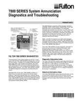
Fig. 1. Mounting dimensions of EC7823/RM7823 Relay Module and Q7800A,B Subbase in in. (mm).
POWER
FLAME
ALARM
RESET
5
(127)
5 (127)
M2649
BURNER CONTROL
REMOVE ONLY FOR TERMINAL TEST ACCESS.
1
1
5-1/4 (133)
POWER
FLAME
ALARM
RESET
5
(127)
5 (127)
M2650
BURNER CONTROL
REMOVE ONLY FOR TERMINAL TEST ACCESS.
1
1
6-3/32 (155)

7800 SERIES EC7823/RM7823 RELAY MODULE
5 66-2031—3
Table 3. Flame Detection System.
a Order flame rod separately; see holder instructions.
b The C7012A,C, C7027, C7035 and C7044 Flame Detectors should be used only on burners that cycle on-off at least once
every twenty-four hours. Appliances with burners that remain on continuously for twenty-four hours or longer should use
the C7012E,F Flame Detector with the R7847C Amplifier; the C7061A Flame Detector with the R7861 Amplifier, or the
C7076A,D Flame Detector with the R7886A Amplifier as the ultraviolet flame detection system.
c Circuitry tests the flame signal amplifier 12 times a minute during burner operation and shuts down the boiler if the
amplifier fails.
d Circuitry tests all electronic components in the flame detection system (amplifier and detector) at least 12 times a minute
during burner operation and shuts down the burner if the detection system fails.
e 220 to 240 Vac application. Requires 220-240 Vac to 120 Vac, 10 VA stepdown transformer to operate the shutter.
Plug-in Flame Signal Amplifiers Applicable Flame Detectors
Type Color Self-Checking Model
Flame Failure
Response
Time Fuel Type Models
Rectification Green No R7847A 0.8 or
3 sec.
Gas Rectifying Flame
Rod Holdersa
C7004, C7007, C7011.
Complete Assemblies:
C7008, C7009, Q179.
3 sec. Gas, oil,
coal.
Ultraviolet
(Purple Peeper®) C7012A,Cb.
Dynamic
AMPLI-CHECK™ R7847Bc0.8 or
3 sec.
Gas Rectifying Flame
Rod Holdersa
C7004, C7007, C7011.
Complete Assemblies:
C7008, C7009, Q179.
3 sec. Gas, oil,
coal
Ultraviolet
(Purple Peeper®) C7012A,Cb.
Dynamic
Self-Check R7847Ce,f C7012E,F.
Infrared Red No 7848A Infrared
(Lead Sulfide)
C7015.
Dynamic
AMPLI-CHECK™ R7848Bc
Ultraviolet Purple No R7849A 0.8 or
3 sec.
Gas, oil Ultraviolet
(Minipeeper) C7027, C7035, C7044b.
Dynamic
AMPLI-CHECK™ R7849Bc
Dynamic
Self-Check R7861Ad,e Ultraviolet C7061.
Blue R7886Ad,e 3 sec Gas, oil,
coal
Ultraviolet
(Adjustable
Sensitivity)
C7076.
Optical White Dynamic
AMPLI-CHECK®
R7851B 0.8/1 or
2/3 sec.
Optical (UV, IR,
Visible Light).
C7927, C7935, C7915,
C7962.

66-2031—3 6

7 66-2031—3

66-2031—3 G.R. Rev. 06-03 www.honeywell.com
Printed in U.S.A. on recycled
paper containing at least 10%
post-consumer paper fibers.
Automation and Control Solutions Honeywell International Honeywell Europe S.A. Honeywell Latin American
Honeywell International Inc. Honeywell Limited-Honeywell Limitée Control Products 3 Avenue du Bourget Region
1985 Douglas Drive North 35 Dynamic Drive Honeywell Building 1140 Brussels 480 Sawgrass Corporate Parkway
Golden Valley, MN 55422 Scarborough, Ontario 17 Changi Business Park Central 1 Belgium Suite 200
M1V 4Z9 Singapore 486073 Sunrise FL 33325
/