Page is loading ...

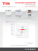
This product is a power supply module designed
to be installed in the junction box to provide 12 V
DC for small power motor drive applications.
PRODUCT INFORMATION
6 58921 79931 4
BARCODE (UPC-A)
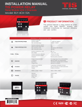
TIS POWER SUPPLY
24-V DC Power Supply Module
INSTALLATION MANUAL
Model: P.S-24V-1.5A
PRODUCT SPECIFICATIONS
Power supply
Input voltage
110/240 VAC 50/60 Hz
Output power 60W / 24V
protection Internal protection fuse
Current consumption 1500 mA / 24 V DC
Mounting Din rail Standard 35 mm din rail
Wall mount screw holder on the back of the module
Dimensions Length × Width × Height 73mm × 76mm × 90mm
Housing
Materials Fireproof ABS
Casing color Black
IP rating IP 20
Temperature range
Operation -30…60°C
Storage -20…60°C
Transport -30…75°C
Air humidity <80% non-condensing

INSTALLATION MANUAL
MODEL : P.S-24V-1.5A
TIS Power SuPPly
2
www.tiscontrol.com
TIS CONTROL LIMITED
Wanchai, Hong Kong
TIS CONTROL PTY LIMITED
SA , AUSTRALIA
Copyright © 2022 TIS, All Rights Reserved
TIS Logo is registered trademark of TIS CONTROL.
All of the specification are subject to change without notice.
Data Cable
Use screened stranded RS485 data cable
with four twisted pairs. Congure devices in
a “Daisy Chain.”
Do not cut or terminate live data cables.
Electrical Wires
The recommended wire size is 4…6mm2
for the Line, Neutral, and Output wires. The
installer should consider the total current
consumption when selecting the wires.
Warranty
There is a two-years warranty provided
by law. The hologram warranty seal and
product serial number are available on
each device.
Read Instructions
We recommend that you read this
Instruction Manual before installation.
Safety instructions
Electrical equipment should only be
installed and tted by electrically skilled
persons.
Failure to observe the instructions may
cause damage to the device and other
hazards.
These instructions are an integral part of
the product and must remain with the end
customer.
Programming
Advanced programming requires TIS
Device Search software. Advanced
software programming knowledge should
be obtained in the advanced training
courses.
Simple Installation
You can use either the DIN rail or xing
points to install this module.
Mounting Location
Install in a dry, well-ventilated location.
Controllers may emit some mechanical
noises. Consider this when deciding on a
mounting location.

INSTALLATION MANUAL
MODEL : P.S-24V-1.5A
TIS Power SuPPly
3
www.tiscontrol.com
TIS CONTROL LIMITED
Wanchai, Hong Kong
TIS CONTROL PTY LIMITED
SA , AUSTRALIA
Copyright © 2022 TIS, All Rights Reserved
TIS Logo is registered trademark of TIS CONTROL.
All of the specification are subject to change without notice.
Turn off the main electrical source before
installation.
1WARNING! HIGH VOLTAGE
INSTALLATION STEPS
Mount the device on DIN rails inside an
approved enclosure. The device can also
be installed using two mounting screw
holes.
2
+24D+D-GND+24D+D-GND
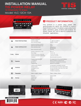
Connect the RS485 data cable to the
TIS-BUS port following the product
connection diagrams.
It is necessary to loop the TIS-BUS cable
if the side bus-train terminal connects the
two DIN rail modules.
3
GND(white-orange)&(white-brown)
D-(white-green)&(white-blue)
D+(blue-green)
+24V(brown-orange)
Cat5e connection
P.S-24V-1.5A
DC
TIS-BUS
GND D+ +24V
D-
NL
To the TIS BUS Network
Cat5e

INSTALLATION MANUAL
MODEL : P.S-24V-1.5A
TIS Power SuPPly
4
www.tiscontrol.com
TIS CONTROL LIMITED
Wanchai, Hong Kong
TIS CONTROL PTY LIMITED
SA , AUSTRALIA
Copyright © 2022 TIS, All Rights Reserved
TIS Logo is registered trademark of TIS CONTROL.
All of the specification are subject to change without notice.
INSTALLATION STEPS
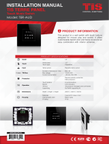
Connect the L, N, and PE to Live, Neutral,
and Earth cables, respectively. The
device input must have an appropriate
MCB to protect the module.
4
Connect To L
Connect To N
1.5 mm Electric Cable
1.5 mm Electric Cable
GND(white-orange)&(white-brown)
D-(white-green)&(white-blue)
D+(blue-green)
+24V(brown-orange)
Cat5e connection
O-OFF
I-ON
MCB P.S-24V-1.5A
DC
TIS-BUS
GND D+ +24V
D-
NL
To the TIS BUS Network
Cat5e
Turn on the power source. The module’s
LED should turn on and supply the BUS
network with 24V DC.
5
GND(white-orange)&(white-brown)
D-(white-green)&(white-blue)
D+(blue-green)
+24V(brown-orange)
Cat5e connection
P.S-24V-1.5A
DC
TIS-BUS
GND D+ +24V
D-
NL
To the TIS BUS Network
Cat5e

INSTALLATION MANUAL
MODEL : P.S-24V-1.5A
TIS Power SuPPly
5
www.tiscontrol.com
TIS CONTROL LIMITED
Wanchai, Hong Kong
TIS CONTROL PTY LIMITED
SA , AUSTRALIA
Copyright © 2022 TIS, All Rights Reserved
TIS Logo is registered trademark of TIS CONTROL.
All of the specification are subject to change without notice.
TROUBLESHOOTING
The DC LED does not turn on Reason: There is no connection to the
L/N input.
The DC LED is ON, but no 24V
DC output
Reason 1: There is a short circuit on the BUS
network.
Reason 2: There is an overload, because
many bus products are connected to the
same power supply.
The DC LED is OFF, and there is
no 24V DC output, even though
the L / N wires are connected.
Reason: Power supply is damaged.
/