Page is loading ...

Preset Protocol Specifications Manual
Part D301254X012
April 2020
Preset Protocol Specifications Manual

Preset Protocol Specifications Manual
ii Contents Revised April 2020
System Training
A well-trained workforce is critical to the success of your operation. Knowing how to correctly
install, configure, program, calibrate, and trouble-shoot your Emerson equipment provides your
engineers and technicians with the skills and confidence to optimize your investment. Remote
Automation Solutions offers a variety of ways for your personnel to acquire essential system
expertise. Our full-time professional instructors can conduct classroom training at several of our
corporate offices, at your site, or even at your regional Emerson office. You can also receive the same
quality training via our live, interactive Emerson Virtual Classroom and save on travel costs. For our
complete schedule and further information, contact the Remote Automation Solutions Training
Department at 800-338-8158 or email us at [email protected].

Preset Protocol Specifications Manual
Revised April 2020 Contents iii
Contents
Chapter 1 – Introduction 1-1
1.1 Manual Organization ...................................................................................................................... 1-1
1.2
General Protocol Message Format ................................................................................................ 1-2
1.3 Broadcast ....................................................................................................................................... 1-3
1.4 Calculating Data Offsets ................................................................................................................ 1-3
Chapter 2 – Opcodes 2-1
2.1 Opcode Overview ........................................................................................................................... 2-1
2.2 Opcode 6, System Configuration ................................................................................................... 2-3
2.3 Opcode 7, Read Real-time Clock ................................................................................................. 2-14
2.4 Opcode 8, Set Real-time Clock .................................................................................................... 2-14
2.5 Opcode 10, Read Configurable Opcode Point Data .................................................................... 2-15
2.6 Opcode 11, Write Configurable Opcode Point Data .................................................................... 2-15
2.7 Opcode 17, Login Request .......................................................................................................... 2-16
2.8 Opcode 24, Store and Forward .................................................................................................... 2-17
2.9 Opcode 50, Request I/O Point Position ....................................................................................... 2-18
2.10 Opcode 100, Access User-defined Information ........................................................................... 2-18
2.11 Opcode 105, Request Today’s and Yesterday’s Min/Max Values ............................................... 2-19
2.12 Opcode 108, Request History Tag and Periodic Index ................................................................ 2-21
2.13 Opcode 117, Request Weights and Measures Event Data ......................................................... 2-22
2.14 Opcode 118, Request Alarm Data ............................................................................................... 2-25
2.15 Opcode 119, Request Event Data ............................................................................................... 2-28
2.16 Opcode 135, Request Single History Point Data ......................................................................... 2-32
2.17 Opcode 136, Request Mutiple History Point Data ....................................................................... 2-34
2.18 Opcode 137, Request History Index for a Day ............................................................................ 2-36
2.19 Opcode 138, Request Daily and Periodic History for a Day ........................................................ 2-37
2.20 Opcode 139, History Information Data ......................................................................................... 2-38
2.21 Opcode 166, Set Single Point Parameters .................................................................................. 2-39
2.22 Opcode 167, Request Single Point Parameters .......................................................................... 2-39
2.23 Opcode 180, Request Parameters............................................................................................... 2-40
2.24 Opcode 181, Write Parameters .................................................................................................... 2-41
2.25 Opcode 203, General File Transfer .............................................................................................. 2-42
2.26 Opcode 224, SRBX Signal ........................................................................................................... 2-44
2.27 Opcode 225, Acknowledge SRBX ............................................................................................... 2-44
2.28 Opcode 255, Error Indicator ......................................................................................................... 2-45
Chapter 3 – Parameter Lists for Point Types 3-1
3.1 Type, Location/Logical, and Parameter (TLPs) ............................................................................. 3-1
3.2 Logical/Location Details ................................................................................................................. 3-1
3.3 Binary Field (BIN) Example ............................................................................................................ 3-2
3.4 Point Type Table Fields ................................................................................................................. 3-3
3.4.1
Point Type 60: Print Parameters ...................................................................................... 3-4
3.4.2 Point Type 61: Transaction History Parameters ............................................................ 3-11
3.4.3 Point Type 62: Keypad Display Parameters .................................................................. 3-45
3.4.4 Point Type 63: General Preset Parameters ................................................................... 3-56
3.4.5 Point Type 64: General Preset Parameters #2 ............................................................ 3-106
3.4.6 Point Type 65: Transaction History Parameters (#2) ................................................... 3-120
3.4.7 Point Type 67: Additives ............................................................................................... 3-128
3.4.8 Point Type 68: Recipes ................................................................................................ 3-134
3.4.9 Point Type 69: Components ......................................................................................... 3-144

Preset Protocol Specifications Manual
iv Contents Revised April 2020
3.4.10 Point Type 70: Liquid Preference Parameters ..............................................................3-160
3.4.11 Point Type 71: Liquid Station Parameters .....................................................................3-163
3.4.12 Point Type 72: Product Parameters ..............................................................................3-173
3.4.13 Point Type 73: Liquid Meter Parameters .......................................................................3-176
3.4.14 Point Type 74: Densitometer Interface Parameters ......................................................3-189
3.4.15 Point Type 75: Meters ...................................................................................................3-195
3.4.16 Point Type 76: Valves ...................................................................................................3-206
3.4.17 Point Type 82: Virtual Discrete Outputs ........................................................................3-208
3.4.18 Point Type 84: HART Extended Point Type ..................................................................3-212
3.4.19 Point Type 85: HART Parameters .................................................................................3-221
3.4.20 Point Type 91: System Variables: .................................................................................3-242
3.4.21 Point Type 92: Logon Parameters.................................................................................3-247
3.4.22 Point Type 95: Communication Port Parameters ..........................................................3-250
3.4.23 Point Type 96: FST Parameters ....................................................................................3-255
3.4.24 Point Type 97: FST Register Tags ................................................................................3-258
3.4.25 Point Type 98: Soft Point Parameters ...........................................................................3-259
3.4.26 Point Type 99: Configurable Opcode Table ..................................................................3-262
3.4.27 Point Type 100: Power Control Parameters ..................................................................3-264
3.4.28 Point Type 101: Discrete Inputs ....................................................................................3-267
3.4.29 Point Type 102: Discrete Outputs .................................................................................3-269
3.4.30 Point Type 103: Analog Inputs ......................................................................................3-272
3.4.31 Point Type 104: Analog Outputs ...................................................................................3-276
3.4.32 Point Type 105: Pulse Inputs ........................................................................................3-278
3.4.33 Point Type 106: RTD .....................................................................................................3-281
3.4.34 Point Type 107: Thermocouple .....................................................................................3-285
3.4.35 Point Type 108: Multi-Variable Sensor ..........................................................................3-288
3.4.36 Point Type 109: System Analog Inputs .........................................................................3-296
3.4.37 Point Type 110: PID Control Parameters ......................................................................3-302
3.4.38 Point Type 117: Modbus Configuration Parameters .....................................................3-309
3.4.39 Point Type 118: Modbus Register to TLP Mapping Parameters ...................................3-312
3.4.40 Point Type 119: Modbus Event, Alarm, and History Table ...........................................3-325
3.4.41 Point Type 120: Modbus Master Modem Configuration ................................................3-334
3.4.42 Point Type 121: Modbus Master Table .........................................................................3-336
3.4.43 Point Type 122: DS800 Configuration ...........................................................................3-347
3.4.44 Point Type 123: Security – Group Configuration...........................................................3-349
3.4.45 Point Type 124: History Segment Configuration ...........................................................3-351
3.4.46 Point Type 125: History Segment 0 Point Configuration ...............................................3-353
3.4.47
Point Type 126: History Segment 1 Point Configuration ...............................................3-355
3.4.48 Point Type 127: History Segment 2 Point Configuration ...............................................3-357
3.4.49 Point Type 128: History Segment 3 Point Configuration ...............................................3-359
3.4.50 Point Type 129: History Segment 4 Point Configuration ...............................................3-361
3.4.51 Point Type 130: History Segment 5 Point Configuration ...............................................3-363
3.4.52 Point Type 131: History Segment 6 Point Configuration ...............................................3-365
3.4.53 Point Type 132: History Segment 7 Point Configuration ...............................................3-367
3.4.54 Point Type 133: History Segment 8 Point Configuration ...............................................3-369
3.4.55 Point Type 134: History Segment 9 Point Configuration ...............................................3-371
3.4.56 Point Type 135: History Segment 10 Point Configuration .............................................3-373
3.4.57 Point Type 136: ROC Clock ..........................................................................................3-375
3.4.58 Point Type 137: Internet Configuration Parameters ......................................................3-377
3.4.59 Point Type 138: User C++ Host Parameters .................................................................3-384
3.4.60 Point Type 139: Smart I/O Module Information .............................................................3-385
3.4.61 Point Type 140: Alternating Current Input / Output .......................................................3-389
3.4.62 Point Type 141: Advance Pulse Module .......................................................................3-397
3.4.63 Point Type 142: History Segment 11 Point Configuration .............................................3-410
3.4.64 Point Type 143: History Segment 12 Point Configuration .............................................3-412
3.4.65 Point Type 144: Transactional History Configuration ....................................................3-414
3.4.66 Point Type 145: Transactional History Point Configuration ..........................................3-415
3.4.67 Point Type 172: RTU Network Discovery List Point Configuration ...............................3-416

Preset Protocol Specifications Manual
Revised April 2020 Contents v
3.4.68 Point Type 173: Network Commissioned List .............................................................. 3-417
3.4.69 Point Type 174: Network Export Data .......................................................................... 3-419
3.4.70 Point Type 175: Network Import Data .......................................................................... 3-420
3.4.71 Point Type 176: IEC62591 Live List Configuration ...................................................... 3-421
3.4.72 Point Type 177: IEC62591 Commissioned List Configuration ..................................... 3-422
Chapter 4 – CRC-16 Code 4-1
Chapter 5 – IEEE Floating Point Format 5-1
Chapter 6 – Spontaneous-Report-By-Exception 6-1
Chapter 7 – Device-to-Device Communications 7-1
Index I-1

Preset Protocol Specifications Manual
vi Contents Revised April 2020

Preset Protocol Specifications Manual
Revised April 2020 Introduction 1-1
Chapter 1 – Introduction
This manual provides information required to understand the ROC Plus
protocol and its implementation within the DL8000 Preset Controller
(“DL8000”). It is written for personnel needing to implement a ROC
Plus Protocol driver in the DL8000 or as a reference to understanding
the ROC Plus communications protocols. This manual is intended for
users experienced in the development of communication drivers. The
protocol provides access to database configuration, real-time clock,
event and alarm logs, and historically archived data.
The ROC Plus database is broken into individual parameters. Each
database parameter is uniquely associated by parameter number and
point type. See Chapter 3, Parameter Lists for Point Types, for detailed
information.
1.1 Manual Organization
This manual is organized into the following chapters:
Chapter
Description
Chapter 1
Introduction
Describes this manual and provides a summary of
the general protocol message format, summary of
each opcode, and how to calculate data offsets.
Chapter 2
Opcodes
Lists each opcode the ROC Plus protocol uses.
Chapter 3
Parameter Lists for
Point Types
Describes ROC Plus protocol point types and data
types.
Chapter 4
CRC-16 Code
Provides information concerning the cyclical
redundancy check the ROC Plus protocol uses.
Chapter 5
IEEE Floating Point
Format
Provides information about the binary representation of
floating-point numbers.
Chapter 6
Spontaneous Report-
by-Exception
Provides information on the DL8000’s Spontaneous
Report-by-Exception (RBX or RBX) function.
Chapter 7
Device to Device
Communications
Provides information detailing store and forward
options in the DL8000.
Index
Provides an alphabetic listing of items and topics
contained in this manual.

Preset Protocol Specifications Manual
1-2 Introduction Revised April 2020
1.2 General Protocol Message Format
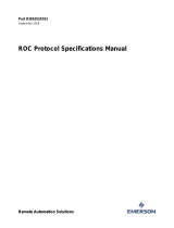
Figure 1-1 shows the various ROC and host protocol message formats.
General Message Format - Station ‘A’ Polling Station ‘B’ for Data/Action:
Destination (B) Source (A) Opcode
Data
Length
m Data Bytes CRC
unit group unit group
# of
bytes
d1 d2 d3 – – – – dm LSB MSB
General Message Format - Station ‘B’ Responding to Station ‘A’:
Destination (A) Source (B) Opcode
Data
Length
n Data Bytes CRC
unit group unit group
# of
bytes
d1 d2 d3 – – – – dn LSB MSB
Figure 1-1. General Message Format
A message generally contains the following fields, in order from left to
right:
Field Description
Destination
Specifies the address for the destination device.
Destination has two components:
Unit
One-byte unit code for the station
address. The unit code for a ROC
address is user-configurable. For a host,
this must be a unique number. 0
represents “broadcast within group” and
240
is the “direct connect address.”
Group
Indicates the group code for the station
address. This is user-configurable and
usually set to
2
.
Source
Specifies the address for the source device. Source
has two components:
Unit
One-byte unit code for the station
address. The unit code for a ROC
address is user-configurable. For a host,
this must be a unique number. 0
represents “broadcast within group” and
240 is the “direct connect address.”
Group
Indicates the group code for the station
address. This is user-configurable and
usually set to 2.
Opcode
Defines the operation code (opcode) action to
perform.
# of bytes
Indicates the number of bytes in the data byte field,
consisting of the path, desired opcode, number of
data bytes for the desired message, and the desired
message itself.
Data Bytes
Contains messages of varying lengths, consisting of
the path, desired opcode, number of data bytes for
the desired message, and the message itself.
CRC
Confirms validity of message transmission.

Preset Protocol Specifications Manual
Revised April 2020 Introduction 1-3
Field
Description
LSB
Least significant byte.
MSB
Most significant byte.
Messages are of flexible length. The first six data bytes are used for the
header information including: destination, source, opcode, and data
length (number of bytes). The length of a message equals the number of
data bytes transmitted plus eight overhead bytes (header information
and CRC).
The minimum message length is eight bytes if the number of data bytes
is zero (no data bytes transmitted). The maximum message length is 248
bytes (240 bytes of data). A “nibble” is a four-bit unit or half a byte.
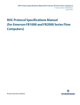
Figure 1-2 provides examples of the messages exchanged if the host
requests the current time and date from DL8000 13 of Group 5.
Host Request to DL8000:
ROC Address Host Address Opcode
Data
Length
CRC
unit group unit group –
# of
bytes
LSB MSB
13
5
1
0
7
0
1
m
DL8000 Response to Host:
Host Address ROC Address Opcode
Data
Length
8 Data Bytes CRC
unit group unit group –
# of
bytes
d1 d2 d3 – – – –- dn LSB MSB
1
0
13
5
7
8
sec
min
hr
day
mo
yr
lyr
dwk
l
m
Figure 1-2. Request/Response Example
Note: Addresses 240,240 and 0,x are reserved and should not be used.
1.3 Broadcast
DL8000 firmware version 1.10 and higher supports message
broadcasting. A broadcast message is an opcode that is sent to a unit of
0. In this case, all DL8000s with the group matching the request accept
the opcode and process it (regardless of the unit designation that each
DL8000 may have). The DL8000 does not respond to the request.
For example, you may need to synchronize several DL8000s to the
same date and time. If the DL8000s were connected to the same radio
link and configured for the same group, a host could send an opcode 8
(Set Real-Time Clock) request to Unit 0 that would then set all of the
DL8000s configured in this group to the same date and time.
1.4 Calculating Data Offsets
A data byte offset is the offset (zero-based) from the beginning of a
transmit or receive buffer for the data items that comprise the opcode

Preset Protocol Specifications Manual
1-4 Introduction Revised April 2020
data. The offset of the first data item is always 6 to allow for the header
information (bytes 0-5).
Certain data offset values are determined based on the DL8000’s
configuration, such as for Opcode 0. The data byte offset for each item
may be calculated. To calculate the next data offset value, add the
previous offset value to the length of the previous data item:
Offset = Previous Offset + Length of Previous Data Item

Preset Protocol Specifications Manual
Revised April 2020 Opcodes 2-1
Chapter 2 – Opcodes
This section details each opcode for the DL8000 preset protocol.
2.1 Opcode Overview
Table 2-1 summarizes each opcode. The tables in this section provide
detailed descriptions of the various opcodes used. For each opcode, a
brief description of the data bytes is provided. In some cases, the
number of data bytes returned for an opcode varies. For example,
Opcode 0, a full update, always returns certain input/output (I/O)
information along with optionally specified data.
Certain opcodes only send data and do not receive data back from the
DL8000. For example, Opcode 8 requests the DL8000 to set the time
and date. The host transmits six to nine data bytes defining the new time
and date. The DL8000 resets the time and date and sends back an
acknowledgment in which the opcode is repeated, but no data bytes are
transmitted back. All acknowledgments are 8-byte messages that repeat
the opcode received, but do not transmit any data bytes.
Opcode 255 is an error message indicator. This is also an 8-byte
message with no data bytes included. The opcode is set to 255 to
indicate the message received by the DL8000 had valid Cyclical
Redundancy Check (CRC), but contained invalid parameters. For
example, if a request was made for information on Analog Input #11,
but the DL8000 was configured for only eight analog inputs (0 to 7), the
DL8000 would respond back with the 8-byte message with the opcode
equal to 255 (error).
The number of analog inputs varies from DL8000 to DL8000. This
variability is indicated by listing the first analog input and indicating the
remaining analog inputs by a period (“.”). In the following tables, a
period in either the Data byte(s) column or the Description of Data
column indicates a repetition of the proceeding item for the necessary
number of instances.

Preset Protocol Specifications Manual
2-2 Opcodes Revised April 2020
Table 2-1. Summary of Opcodes
Opcode
Description
6
Sends DL8000 configuration.
7
Sends current time and date.
8
Sets new time and date.
10
Sends data from configurable opcode tables.
11
Sets data in configurable opcode tables.
17
Sets operator identification.
24
Stores and forwards.
50
Requests IO point position array.
100
Reads user-defined point information (Command 11)
105
Sends history point definition, min/max data, and current values for specified history point.
108
Sends tag and current history period for specified history points.
117
Sends specified number of weights and measures events starting at specified event index
118
Sends specified number of alarms starting at specified alarm index.
119
Sends specified number of events starting at specified event index.
135
Requests history point data.
136
Requests history index data.
137
Requests history index for a day.
138
Requests daily and periodic history for a day.
139
Requests various types of information from history.
166
Sets specified contiguous block of parameters.
167
Sends specified contiguous block of parameters.
180
Sends specified parameters.
181
Sets specified parameters.
203
File transfer to and from DL8000.
204
Sends specified number of events or weights and measures events starting at specified event indice
(supporting 40-byte old and new value on parameter change)
224
Sends Report-by-Exception (SRBX) message to host.
225
Acknowledges Report-by-Exception message from DL8000.
255
Transmits DL8000 error messages in response to a request with invalid parameters or format.

Preset Protocol Specifications Manual
Revised April 2020 Opcodes 2-3
2.2 Opcode 6, System Configuration
Opcode 6 obtains the current configuration of the DL8000.
Version
Description
1.10
Introduced
Table 2–2. Opcode 6, System Configuration
Communi-
Host Request to DL8000
DL8000 Response to Host
cation
Data
Data
Opcode
Offset
Length
Description of Data
Offset
Length
Description of Data
Opcode 6:
System
Configura-
tion
6
No data bytes
6
1
The system mode the unit is
currently operating in.
0 = Firmware Update Mode –
Extremely limited functionality is
available.
1 = Run Mode
7
2
Comm Port or Port Number that this
request arrived on. This is not
defined if the above value (offset 6)
is 0.
9
1
Security Access Mode for the port
the request was received on.
10
1
Logical Compatibility Status –
Version 1.10
See [Point Type 91,Logical
0,Parameter 50]:
0 = 16 points per slot (160 bytes
total) – Compatibility Mode is 0 & 9
module slots max
1 = 16 points per slot (240 bytes
total) – Compatibility Mode is 0 & 14
module slots max. NOTE: The 15
th
module slot can not be used.
2 = 8 points per slot (224 bytes
total) – Compatibility
Mode is 1 & 27 module slots max.
See Opcode 50 for more
information.
11
1
Opcode 6 Revision
0 = Original (ROC800 Pre-2.02)
1 = Extended for Additional Point
Types (offset 104 -220)
12
12
Reserved for Future Use [zeros
returned]

Preset Protocol Specifications Manual
2-4 Opcodes Revised April 2020
Communi-
Host Request to DL8000
DL8000 Response to Host
cation
Data
Data
Opcode
Offset
Length
Description of Data
Offset
Length
Description of Data
24
1
Type of ROC
1 = ROCPAC ROC 300 series
2 = FloBoss 407
3 = FlashPAC ROC 300 series
4 = FloBoss 503
5 = FloBoss 504
6 = ROC800 (827/809)
11=DL8000
X = FB100
25
1
Contains the number of logical for
point type 60
26
1
Contains the number of logical for
point type 61
27
1
Contains the number of logical for
point type 62
28
1
Contains the number of logical for
point type 63
29
1
Contains the number of logical for
point type 64
30
1
Contains the number of logical for
point type 65
31
1
Contains the number of logical for
point type 66
32
1
Contains the number of logical for
point type 67
33
1
Contains the number of logical for
point type 68
34
1
Contains the number of logical for
point type 69
35
1
Contains the number of logical for
point type 70
36
1
Contains the number of logical for
point type 71
37
1
Contains the number of logical for
point type 72
38
1
Contains the number of logical for
point type 73
39
1
Contains the number of logical for
point type 74
40
1
Contains the number of logical for
point type 75
41
1
Contains the number of logical for
point type 76
42
1
Contains the number of logical for
point type 77
43
1
Contains the number of logical for
point type 78
44
1
Contains the number of logical for
point type 79
45
1
Contains the number of logical for
point type 80

Preset Protocol Specifications Manual
Revised April 2020 Opcodes 2-5
Communi-
Host Request to DL8000
DL8000 Response to Host
cation
Data
Data
Opcode
Offset
Length
Description of Data
Offset
Length
Description of Data
46
1
Contains the number of logical for
point type 81
47
1
Contains the number of logical for
point type 82
48
1
Contains the number of logical for
point type 83
49
1
Contains the number of logical for
point type 84
50
1
Contains the number of logical for
point type 85
51
1
Contains the number of logical for
point type 86
52
1
Contains the number of logical for
point type 87
53
1
Contains the number of logical for
point type 88
54
1
Contains the number of logical for
point type 89
55
1
Contains the number of logical for
point type 90
56
1
Contains the number of logical for
point type 91
57
1
Contains the number of logical for
point type 92
58
1
Contains the number of logical for
point type 93
59
1
Contains the number of logical for
point type 94
60
1
Contains the number of logical for
point type 95
61
1
Contains the number of logical for
point type 96
62
1
Contains the number of logical for
point type 97
63
1
Contains the number of logical for
point type 98
64
1
Contains the number of logical for
point type 99
65
1
Contains the number of logical for
point type 100
66
1
Contains the number of logical for
point type 101
67
1
Contains the number of logical for
point type 102
68
1
Contains the number of logical for
point type 103

Preset Protocol Specifications Manual
2-6 Opcodes Revised April 2020
Communi-
Host Request to DL8000
DL8000 Response to Host
cation
Data
Data
Opcode
Offset
Length
Description of Data
Offset
Length
Description of Data
69
1
Contains the number of logical for
point type 104
70
1
Contains the number of logical for
point type 105
71
1
Contains the number of logical for
point type 106
72
1
Contains the number of logical for
point type 107
73
1
Contains the number of logical for
point type 108
74
1
Contains the number of logical for
point type 109
75
1
Contains the number of logical for
point type 110
76
1
Contains the number of logical for
point type 111
77
1
Contains the number of logical for
point type 112
78
1
Contains the number of logical for
point type 113
79
1
Contains the number of logical for
point type 114
80
1
Contains the number of logical for
point type 115
81
1
Contains the number of logical for
point type 116
82
1
Contains the number of logical for
point type 117
83
1
Contains the number of logical for
point type 118
84
1
Contains the number of logical for
point type 119
85
1
Contains the number of logical for
point type 120
86
1
Contains the number of logical for
point type 121
87
1
Contains the number of logical for
point type 122
88
1
Contains the number of logical for
point type 123
89
1
Contains the number of logical for
point type 124

Preset Protocol Specifications Manual
Revised April 2020 Opcodes 2-7
Communi-
Host Request to DL8000
DL8000 Response to Host
cation
Data
Data
Opcode
Offset
Length
Description of Data
Offset
Length
Description of Data
90
1
Contains the number of logical for
point type 125
91
1
Contains the number of logical for
point type 126
92
1
Contains the number of logical for
point type 127
93
1
Contains the number of logical for
point type 128
94
1
Contains the number of logical for
point type 129
95
1
Contains the number of logical for
point type 130
96
1
Contains the number of logical for
point type 131
97
1
Contains the number of logical for
point type 132
98
1
Contains the number of logical for
point type 133
99
1
Contains the number of logical for
point type 134
100
1
Contains the number of logical for
point type 135
101
1
Contains the number of logical for
point type 136
102
1
Contains the number of logical for
point type 137
103
1
Contains the number of logical for
point type 138
Included if
Opcode 6
Revision
(offset 11)
>= 1
104
1
Contains the number of logical for
point type 139
105
1
Contains the number of logical for
point type 140
106
1
Contains the number of logical for
point type 141
107
1
Contains the number of logical for
point type 142
108
1
Contains the number of logical for
point type 143
109
1
Contains the number of logical for
point type 144
110
1
Contains the number of logical for
point type 145

Preset Protocol Specifications Manual
2-8 Opcodes Revised April 2020
Communi-
Host Request to DL8000
DL8000 Response to Host
cation
Data
Data
Opcode
Offset
Length
Description of Data
Offset
Length
Description of Data
111
1
Contains the number of logical for
point type 146
112
1
Contains the number of logical for
point type 147
113
1
Contains the number of logical for
point type 148
114
1
Contains the number of logical for
point type 149
115
1
Contains the number of logical for
point type 150
116
1
Contains the number of logical for
point type 151
117
1
Contains the number of logical for
point type 152
118
1
Contains the number of logical for
point type 153
119
1
Contains the number of logical for
point type 154
120
1
Contains the number of logical for
point type 155
121
1
Contains the number of logical for
point type 156
122
1
Contains the number of logical for
point type 157
123
1
Contains the number of logical for
point type 158
124
1
Contains the number of logical for
point type 159
125
1
Contains the number of logical for
point type 160
126
1
Contains the number of logical for
point type 161
127
1
Contains the number of logical for
point type 162
128
1
Contains the number of logical for
point type 163
129
1
Contains the number of logical for
point type 164
130
1
Contains the number of logical for
point type 165

Preset Protocol Specifications Manual
Revised April 2020 Opcodes 2-9
Communi-
Host Request to DL8000
DL8000 Response to Host
cation
Data
Data
Opcode
Offset
Length
Description of Data
Offset
Length
Description of Data
131
1
Contains the number of logical for
point type 166
132
1
Contains the number of logical for
point type 167
133
1
Contains the number of logical for
point type 168
134
1
Contains the number of logical for
point type 169
135
1
Contains the number of logical for
point type 170
136
1
Contains the number of logical for
point type 171
137
1
Contains the number of logical for
point type 172
138
1
Contains the number of logical for
point type 173
139
1
Contains the number of logical for
point type 174
140
1
Contains the number of logical for
point type 175
141
1
Contains the number of logical for
point type 176
142
1
Contains the number of logical for
point type 177
143
1
Contains the number of logical for
point type 178
144
1
Contains the number of logical for
point type 179
145
1
Contains the number of logical for
point type 180
146
1
Contains the number of logical for
point type 181
147
1
Contains the number of logical for
point type 182
148
1
Contains the number of logical for
point type 183
149
1
Contains the number of logical for
point type 184
150
1
Contains the number of logical for
point type 185

Preset Protocol Specifications Manual
2-10 Opcodes Revised April 2020
Communi-
Host Request to DL8000
DL8000 Response to Host
cation
Data
Data
Opcode
Offset
Length
Description of Data
Offset
Length
Description of Data
151
1
Contains the number of logical for
point type 186
152
1
Contains the number of logical for
point type 187
153
1
Contains the number of logical for
point type 188
154
1
Contains the number of logical for
point type 189
155
1
Contains the number of logical for
point type 190
156
1
Contains the number of logical for
point type 191
157
1
Contains the number of logical for
point type 192
158
1
Contains the number of logical for
point type 193
159
1
Contains the number of logical for
point type 194
160
1
Contains the number of logical for
point type 195
161
1
Contains the number of logical for
point type 196
162
1
Contains the number of logical for
point type 197
163
1
Contains the number of logical for
point type 198
164
1
Contains the number of logical for
point type 199
165
1
Contains the number of logical for
point type 200
166
1
Contains the number of logical for
point type 201
167
1
Contains the number of logical for
point type 202
168
1
Contains the number of logical for
point type 203
169
1
Contains the number of logical for
point type 204
170
1
Contains the number of logical for
point type 205
/