112594947_E_EN_2308_Condair-RH_IM Installation Instructions
B
D
D
C
F
A
B
C
E
A
B
CD
A
B
C
D
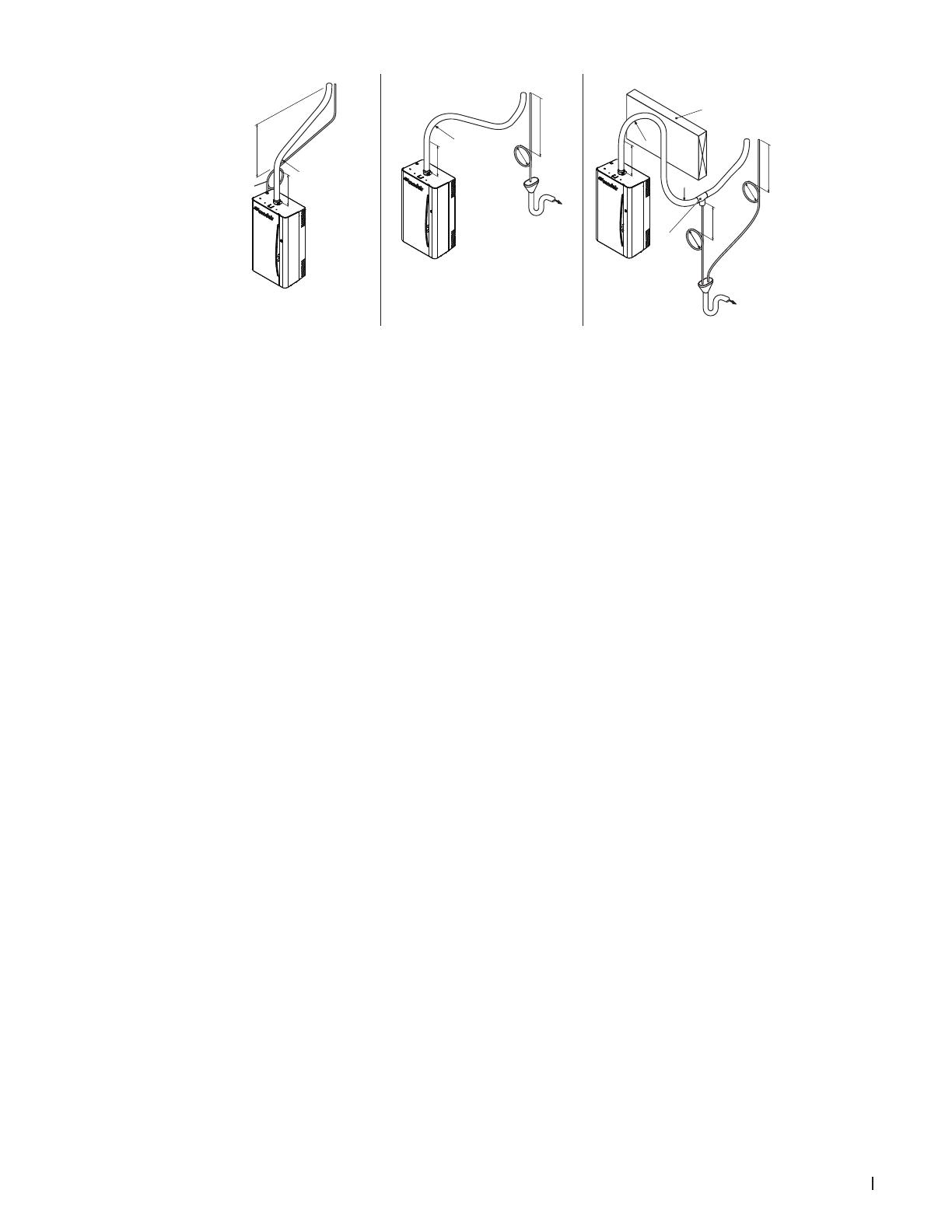
)2()1( (3)
Figure 8 - Considerations for the Steam and Condensate Line (Remote Installations)
1 Typical installation
2 Distributor less than 20 in (500 mm)
abovehumidier.
3 Distributor less than 20 in (500 mm)
abovehumidier,withobstruction.
A 6in(150mm)risebeforebends.
B Condensatetrapsbelowthecondensate
outletonthesteamdistributor,min.
12in(300mm).
C Steamlineshorterthan15ft(4.5m).
D Condensatetrapshaveamin.heightof
6in(150mm).
E Wall,orotherobstacle.
F Condensateline,atlowestpoint,con-
nectedtoT-connector.
Considerations when installing the steam distributor:
• Do NOT exceed the maximum recommended steam line length, 15 ft (4.5 m).
• Do NOT over tighten hose clamps at the steam outlet. Max torque: 12 in·lbs(1.36 Nm).
• Ensure the steam line material is Condair-supplied, otherwise copper or stainless steel.
• Ensure the steam line out of the humidier is vertical 6 in (15 cm) min. before any bends.
• Install the steam distributor as close as possible to the humidier. Short distances minimize condensate
losses and reduces the possibility of back pressure in the distribution line.
• Insulate the steam lines to reduce heat loss and condensate. Use 1.0 in (2.5 cm) pipe insulation, rated
for 212 °F (100 °C) (recommended).
• Use the appropriate slope for the steam line.
– The steam line should have a slope greater than 15° (above the horizontal) away from the humidi-
er for upward traveling steam.
– The steam line should have a slope greater than 2° (below the horizontal) for downward travel-
ing steam. Condensate should be removed from the steam line at low points using a T-connector
condensate trap (not supplied).
• Support the steam line with brackets because the steam hose will soften, and to reduce the weight on
the cylinder.
Condensate Line Considerations:
• Use condensate traps wherever condensate may form along the steam line. For example, at low
points along the line, at horizontal-vertical transitions, or after long distances.
• P-traps located a minimum of 12 in (30 cm) below the duct.
• P-trap height minimum of 6 in (15 cm), or duct pressure + 2 in (5cm).
• Down slope of 1in/48in (1.2°), minimum.


