Page is loading ...

ENGINEERING MANUAL
Electrode Steam Humidifier
Nortec EL-Series
2577597_E_EN_2008_Nortec-EL_EM
Humidication and Evaporative Cooling
NORTEC

Thank you for choosing Condair.
Proprietary Notice
This document and the information disclosed herein are proprietary data of Condair Ltd. Neither this document, nor
the information contained herein shall be reproduced, used, or disclosed to others without the written authorization
of Condair Ltd., except to the extent required for selection, installation, operation or maintenance of the equipment.
Liability Notice
Condair Ltd. does not accept any liability due to incorrect installation, maintenance or operation of the equipment,
or due to the use of parts/components/equipment that are not authorized by Condair Ltd.
Copyright Notice
© Condair Ltd, All rights reserved.
Modication rights reserved.

3Contents
Nortec EL
2577597_E_EN_2008_Nortec-EL_EM
Contents
1 NortecELElectrodeSteamHumidier 5
1.1 General Description 5
1.2 Features 6
1.2.1 Detailed Features List 7
1.3 Options 8
1.4 Accessories 9
1.5 Humidier Components 10
1.6 User Interface 14
2 Operation 15
2.1 General 15
2.2 Sequence of Operation 16
2.3 Drain Cycles 18
2.3.1 Drain Cycle Activation 18
2.3.2 Drain Volume 19
2.4 Steam Cylinders 20
2.4.1 Water Conditions Versus Cylinder Life 20
2.4.2 Output Versus Cylinder Life 21
3 ProductSpecications 23
3.1 Model Specications 23
3.1.1 Model Designation 23
3.1.2 Nortec EL Specications 24
3.2 Specication Drawings 29
4 Planning 35
4.1 Location and Clearances 35
4.2 Services 36
4.3 Installation Requirements 38
4.3.1 Humidier Mounting 38
4.3.2 Water and Drainage Connections 39
4.3.3 Steam Distribution 40
4.3.3.1 Duct Distributors 40
4.3.3.2 Blower Packs 41
4.3.3.3 Atmospheric Steam and Condensate Lines 42
4.3.4 Electrical Connection 46
4.4 Control System Design 47
4.4.1 Control Signal Input 48
4.4.1.1 Analog Control Signals 48
4.4.1.2 Digital Control Signals 49
4.4.2 Condair Linkup 50
4.4.3 Humidity Control Design 51
4.4.3.1 Duct Distribution Control Design 51
4.4.3.2 Space Distribution Control Design 53
4.4.4 Remote Fault Indication Board 54
4.4.5 Accessory Board 55
4.5 Preventative Maintenance 56

4 Contents
2577597_E_EN_2008_Nortec-EL_EM Nortec EL
5 TotalHumidicationLoadCalculation 57
5.1 Total Humication Load 57
5.1.1 Calculating Base Humidication Load 58
5.1.1.1 Total Unconditioned Air Supply Volume 58
5.1.1.2 Unconditioned Supply Air Moisture 58
5.1.1.3 Conditioned Air Moisture 59
5.1.1.4 Base Humidication Load 59
5.1.2 Moisture Content Equilibrium 60
5.1.3 Condensate Loss 61
6 Product Selection 63
6.1 Humidier and Options 63
6.2 Steam Distribution Equipment 65
A Appendix 67
A.1 Sample Specication 67
A.2 Blank Schedule 69

5Nortec EL Electrode Steam Humidier
Nortec EL
2577597_E_EN_2008_Nortec-EL_EM
1 NortecELElectrodeSteamHumidier
1.1 General Description
The Nortec EL humidier is an atmospheric steam generator, which operates on the electrode heating
principle – heat is generated by the resistance to ow of electric charge between electrodes immersed
in water. The Nortec EL humidier is designed for direct room humidication using a blower pack, or
humidication through the ducts in an air handling unit using a steam distributor. It is suitable for a variety
of humidication applications including commercial oces, hospitals, computer rooms, museums, clean
rooms, schools, printing plants, and other applications where reliability is required.
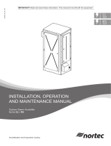
The Nortec EL humidier comes in three dierent housing sizes – small, medium and large depending
on the steam output. The small model has capacities ranging from 5 lb/h (2 kg/h) to 30 lb/h (14 kg/h), the
medium model from 50 lb/h (23 kg/h) to 100 lb/h (45 kg/h), and the large model from 150 lb/h (68 kg/h)
to 200 lb/h (91 kg/h). The small and medium size models can be ordered with a built-on blower pack.
Refer to Figure 1. Table 8 on page 24, Table 9 on page 26 and Table 10 on page 27 list the specications for
each model.
The large model has two steam cylinders instead of one. The construction is similar to the single cylinder
units except that it has two ll and drain connections, and two driver boards and low voltage terminal
strips – one for each steam cylinder (designated "A" and "B"). The separate driver boards and low volt-
age terminal strips allow the large model to handle two separate sets of control signals. This gives the
large Nortec EL humidier the exibility to operate in independent mode, parallel mode or series mode
so it can control humidity in up to two dierent zones.
In independent mode, each steam cylinder operates independent of the other to control humidity in two
separate zones. The control signals are wired to the driver board and low voltage terminal strip that
controls the corresponding zone.
In parallel mode, one set of control signals is wired to the driver board and low voltage terminal strip for
steam cylinder "A", which controls the humidity in both zones. Both steam cylinders respond equally to
the demand for humidity.
In series mode, one set of control signals is wired to the driver board and low voltage terminal strip for
steam cylinder "A", which control the humidity in both zones. In this mode, both steam cylinders operate
in a staged fashion – steam cylinder "A" can be congured to handle output from 0-50% of demand, and
cylinder "B" from 50-100% of demand. The advantage is that it permits the unit to vary its output from
25-100% of its capacity – 25% being the minimum output capacity of each steam cylinder.
Figure 1:
4
1
3
5
2
6
7
Nortec EL Humidier Models
1 EL005-030 – small model with single steam cylinder
2 EL005-030 – small model with single steam cylinder and
built-on blower pack
3 EL050-100 – medium model with single steam cylinder
4 EL050-100 – medium model with single steam cylinder
and built-on blower pack
5 EL150-200 – large model with dual steam cylinders
6 Steam cylinder "A", large model
7 Steam cylinder "B", large model

6 Nortec EL Electrode Steam Humidier
2577597_E_EN_2008_Nortec-EL_EM Nortec EL
1.2 Features
The Nortec EL humidier has many advanced features that set it apart from other humidiers.
• Pure, clean steam at an economical price.
• Easiest commercial humidier to install and maintain. Fully congured and packaged unit that is
ready to install out-of-the-box.
• Patented Auto-adaptive Control minimizes water usage.
• State-of-the-art touchscreen controller provides great user experience and advanced user controls.
• Robust product from the company that has been in the market for over 40 years, and continues to
perfect humidication technology.
• Zero side clearance for small installation footprint.
• Certied to meet OSHPD seismic requirements.
• Extremely ecient boiling process, electrical current passes directly through water.
• Standard integration into building management systems (BMS) using Modbus, BACnet MS/TP or
BACnet IP. Other protocols are available as options.
• Standard drain water cooling which tempers drain water to meet local plumbing code requirements
before it is emptied into the drain.
• USB port for loading software updates and downloading performance data.
• Connect up to 12 steam cylinders together in a "Main-Extension" conguration using Condair Linkup
to satisfy large humidication needs.
• SIM card for storage of operating parameters and settings.
• Aesthetic cabinet design.
• Remote interface to control and modify humidier settings.
Refer also to the detailed features listed in Table 1.

7Nortec EL Electrode Steam Humidier
Nortec EL
2577597_E_EN_2008_Nortec-EL_EM
1.2.1 Detailed Features List
Table 1: Nortec EL Features
Feature Description
Nortec EL
Standard Optional
Control and User Interface Features
Touchscreen interface Intuitive user interface to congure and monitor the humidi-
er.
Digital graphic display Displays visual feedback of the humidier inputs (conditioned
environment humidity and setpoints).
On/O control Operate the equipment with simple On/O controls.
Up to two modulating control
inputs per cylinder
Allows modulating humidier output to improve accuracy of
supply humidity.
Integrated PI controller Provides direct compatibility with humidity transducers (RH
sensor) with adjustable setpoints and P/I parameters.
Demand signal acceptance Provides direct compatibility with modulating demand signals.
Digital communication
protocols
Provides BMS interface with integrated BACnet IP, BACnet
MS/TP and Modbus protocols.
BTL-certied protocols Provides BTL-certied BACnet IP, BACnet MS/TP connectiv-
ity, and enables use of LonWorks.
Remote fault indication board Allows dry contact feedback on unit operation.
Accessory relay board Allows enabling/disabling of accessory devices such as fans
and valves.
Remote interface Allows direct Ethernet access to the humidier through a PC.
Independent circuits on multi-
cylinder humidiers
Allows for independent control of multiple humidier cylinders
through a common control system.
Status indicator LED Provides quick feedback on operating status of the unit.
Adjustable units of measure Display settings in metric or imperial units of measure.
Manual output adjustment Provides the ability to limit the maximum steam output of the
humidier.
Operation and Maintenance
Auto pulse drain valve Clears potential drain obstructions.
Disposable cylinder Allows for fast, clean, simple service of the humidier.
Auto-adaptive control system Ecient water consumption and humidier performance.
Drain water cooling Drain water tempered to 140 °F (60 °C) during normal and
manual operation.
Extreme drain water cooling Drain water tempered to 120 °F (49 °C) during normal and
manual operation.
Potable drinking water usage Compatible with standard potable water supplies.
Foam detection Standard foam detection and correction capability.
Advanced foam detection Advanced foam detection and correction capability.
Backow prevention Integrated air gap in ll cup provides protection for supply
water systems.
Extended ll cup Accommodates backpressure up to 10 in H20 (2.49 kPa).
Keep Warm function Provides improved humidier response time.
Short cycling detection and
correction
Prevents operational problems associated with seasonal
shifts in humidity load.
Other
C-UL-US Listed Certied to meet product standards as detailed by Underwrit-
ers Laboratories.
OSHPD seismic certication Certied to meet OSHPD seismic requirements.
Warranty Provides guarantee against manufacturer defects. Refer to
"Warranty".
Choice of steam distribution* Allows for distribution to the conditioned environment directly
with the Nortec EL Space model, or indirectly through duct
distributors.
Wall mounting Provides a convenient means of integrating humidication
needs.
* The Nortec EL Space model includes a steam distributor.

8 Nortec EL Electrode Steam Humidier
2577597_E_EN_2008_Nortec-EL_EM Nortec EL
1.3 Options
Table 2 lists the options available for the Nortec EL humidier. Detailed installation instructions are sup-
plied with each option.
Table 2: Nortec EL Options
Option
Availability
Description
Factory
Installed
Field Install
Kit
Built-on blower pack
A blower pack is used to distribute steam generated by
the humidier directly into a conditioned environment. The
Nortec EL Space model comes with a factory-installed
blower pack and internal steam and condensate connec-
tions. A remote-mounted blower pack is also available. Refer
to "Blower Packs" on page 41 for more information.
Mounting bar
Provides two mounting bars which t into each other for
wall mounting. One bar is fastened to the humidier, and
the other bar is fastened to the wall. The unit can be hung
onto the wall by engaging the two mounting bars. Note: The
unit can also be wall-mounted (without this option) using the
keyhole cutouts on the back of the humidier housing.
Mounting rack
Stand-alone rack for mounting the Nortec EL humidier.
Remote fault indication board
Printed circuit board (PCB) with relay contacts for connect-
ing remote status displays for “Unit On”, “Steam”, “Error” and
“Service”. Refer to "Remote Fault Indication Board" on page 54.
Accessory board
PCB with relay contacts for connecting other accessories
such as fans and supply water ushing valves. Refer to "Ac-
cessory Board" on page 55.
Factory-congured control
settings
The humidier can be factory-congured for the requested
control signal acceptances. The humidier can also be
recongured in the eld, as needed. Refer to Table 6 on
page 13 for standard part numbers.
Internal primary fusing
Internal fuse for heating voltage power supply. Only avail-
able as a factory-installed option. Note: This is NOT a
substitute for a dedicated external disconnect switch. Refer
to Table 5 on page 12 for part numbers.
Fill cup extension
Kit for extending the ll cup so the humidier can accommo-
date backpressure up to 10 in H20 (2.49 kPa).
Extreme drain water cooling
Kit for cooling drain water to less than 120 °F (49 °C) before
it is discharged into the drain.
Advanced foam detection
Kit for extending the ability of the humidier to handle a
wider range of water supply quality.
BTL-certied BACnet MS/TP
digital communications
PCB to provide BTL-certied BACnet MS/TP connectivity.
This option also enables full Master functionality when using
BACnet MS/TP.
BTL-certied BACnet IP
digital communications
PCB to provide BTL-certied BACnet IP connectivity.
LonWorks digital communica-
tions
Supplementary board to provide LonWorks connectivity.
Spare steam cylinder
Spare steam cylinders to ensure minimal downtime. Refer to
Table 8 on page 24 for standard steam cylinders.
Remote blower pack power
kit
Kit consists of a transformer, fusing, and a terminal block to
supply power to the remote-mounted blower pack. Without
this option, a separate 110-120 V supply must be supplied
for the remote-mounted blower pack.

9Nortec EL Electrode Steam Humidier
Nortec EL
2577597_E_EN_2008_Nortec-EL_EM
1.4 Accessories
Table 3 lists the accessories available for the Nortec EL humidier. Detailed installation instructions are
supplied with each accessory. Standard part numbers are also listed below.
Table 3: Nortec EL Accessories
Accessory Description
External condensate cooling Self-actuated and electric condensate waste water coolers are used to reduce waste water
temperatures to below 140 °F (60 °C) before it is discharged into drains.
Steam distributor Steam distributors are used for adding steam into ventilation ducts. They are available in
three dierent steam capacities and various lengths to suit duct dimensions.
Refer to Steam Distributor Installation Manual (document 2556592) for additional details and
part numbers.
SAM-e and Mini SAM-e
distribution manifolds
The SAM-e distribution manifolds are used for adding steam into ventilation ducts larger than
24 in (6 cm) where either higher steam capacity or short absorption distance is required. The
Mini SAM-e is available in dimensions under 24 in (61 cm). They are available in a range of
sizes and steam capacities to match duct and humidier requirements.
Refer to SAM-e Engineering Manual (document 1503529) for additional details and part
numbers.
Remote blower pack Blower packs are used for direct humidication of the conditioned environment. Blower
packs are capable of distributing up to 100 lb/h (45 kg/h), should be selected to match or
exceed humidier capacity.
Refer to Blower Pack Installation, Operation and Maintenance Manual (document 2582277)
for additional details.
On/O humidistats Condair oers a range of digital and mechanical On/O duct and wall-mounted humidistats
for use with control and high limit applications. Refer to Table 7 on page 13.
Modulating humidistats Condair oers a range of digital modulating duct and wall-mounted humidistats for use with
control and high limit applications. Refer to Table 7 on page 13.
Outdoor temperature sensors Provides automatic humidistat setpoint reduction to prevent condensation on windows/sur-
faces adjacent to outdoor air. Refer to "Outdoor Temperature Setback" on page 52 for additional
details.
2520263 – Duct-mounted temperature sensor
2553858 – Outdoor mounted temperature sensor
Humidity transducers Condair oers a range of digital humidity sensors for duct and wall-mounting for use with
control and high limit applications. Refer to Table 7 on page 13.
Air proving switch Provides a mechanical dierential pressure switch to enable humidier operation when
there is airow through the ventilation ducts. Adjustable for pressures 0.05-12 in H2O (0.01-
2.99 kPa). Refer to "Air Proving Switch" on page 51 for additional details.
Steam line reducers Provides a means of adapting steam line diameters to match the diameter of the steam
distributor.
1507846 – Steam line reducer (1-3/4 in to 7/8 in) copper
1508165 – Steam line reducer (1-3/4 in to 7/8 in) stainless steel
Condair exible steam and
condensate hose
Steam hoses can be used as steam distribution lines or as couplers between copper or
stainless steel steam distribution lines. When used for steam distribution the maximum rec-
ommended hose length is 10 ft (3 m). Steam hose is available in two sizes.
Condensate hose can be used for draining condensate, or coupling to copper or stainless
steel condensate lines.
1328810 – Steam hose (7/8 in I.D.) per foot (30 cm)
1328820 – Steam hose (1-3/4 in I.D.) per foot (30 cm)
1328840 – Condensate hose (3/8 in I.D.) per foot (30 cm)
Large/small condensate trap
tee
Condensate trap tee must be used to remove condensate that forms in steam distribution
lines. Condair oers tees to match large and small steam lines.
1329634 – Condensate trap tee – small (7/8 × 7/8 × 3/8 in)
1329635 – Condensate trap tee – large (1-3/4 × 1-3/4 × 3/8 in)
In-line water lter and re-
placement lter elements
In-line water lter to remove sediments in the supply water that can obstruct the ll valve
strainer or drain ttings.
1329505 – In-line water lter (5 micron)
1329561 – Replacement lter elements (1 micron)
1329506 – Replacement lter elements (5 micron)

10 Nortec EL Electrode Steam Humidier
2577597_E_EN_2008_Nortec-EL_EM Nortec EL
Table 3: Nortec EL Accessories, continued...
Accessory Description
Condensate pump High temperature condensate pump for pumping waste water from the Nortec EL or con-
densate from the distributor systems.
1429527 – Drain water sump pump, low ow
2524504 – Electric sump pump, medium ow
2576898 – Electric sump pump, high ow
Drain air gap reducer All Nortec EL humidiers require an air gap in the drain line as close as possible to the hu-
midier. The air gap reducer is a 2-1/2 in to 7/8 in (63.5 mm to 22 mm) tting that can provide
the required air gap.
2522172 – External drain air gap reducer
Pocket hygro-thermometer
digital display
The pocket hygro-thermometer provides a means to check the humidity and temperature in a
space. It is a useful tool for troubleshooting humidity problems.
1469595 – Pocket hygro-thermometer digital display
Transformer, plug-In,
120 VAC to 24 VAC
“Wall Wart” AC adaptor 120 VAC to 24 VAC, 40 VA for providing power to remote electronics/
controls.
1603032 – Transformer, plug-In, 120 VAC to 24 VAC
1.5 HumidierComponents
Figure 2 shows the various components of the Nortec EL humidier. The door panels have been removed
for clarity.
Figure 2:
1
2
3
5
8
9
12
13
15
16
17
18
19
21
23
25
6
10
11
20
22
24
14
4
7
Nortec EL Humidier Components (Medium Size Model Shown)
1 Contactor
2 Driver board
3 Terminal block, high voltage supply
4 Specication label
5 Transformer
6 Remote fault indication PCB
7 Integrated control board
8 Cylinder strap
9 Electrode plug
10 Steam outlet hose (optional)
11 Steam adaptor (optional)
12 Sensor, high water level (orange wire)
13 Low voltage terminal strip
14 Front panel
15 Touchscreen display
16 On/Off switch
17 Drain canal
18 Drain valve
19 Steam cylinder
20 Fill hose (ll cup to cylinder)
21 Fill valve
22 Fill hose (ll valve to ll cup)
23 Steam outlet, steam cylinder
24 Overow hose
25 Fill cup

11Nortec EL Electrode Steam Humidier
Nortec EL
2577597_E_EN_2008_Nortec-EL_EM
The Nortec EL humidier housing contains two cabinets – the plumbing cabinet (on the left) and the
controls cabinet (on the right) – refer to Figure 2 on page 10. Table 4 summarizes the functions of the main
components in these two cabinets.
Table 4: Nortec EL Humidier Component Functions
Component Function
Plumbing cabinet
Steam cylinder Water reservoir in which boiling takes place. It houses a set of electrodes that are
used to boil the water. It has a steam outlet at the top, and a water inlet/outlet at the
bottom.
Electrode plug Insulated connector that feeds electric current to the electrodes housed in the steam
cylinder.
High water sensor Detects maximum water level in the steam cylinder.
Drain canal Combined drain outlet for discharge from the steam cylinder, and overow from the ll
cup.
Drain valve Controls the ow of feed water from the ll cup into the steam cylinder, and drain wa-
ter out of the steam cylinder. The stem of the steam cylinder (which houses its water
inlet/outlet) ts into the valve body.
Fill cup Provides a gravity feed means to ll the steam cylinder through the drain valve. A built-
in air gap prevents backow.
Fill valve Controls the ow of feed water into the ll cup.
Fill cup extension (optional) Optional kit for extending the ll cup so the humidier can accommodate backpressure
up to 10 in H2O (2.49 kPa).
Extreme drain water cooling
valve (optional)
Optional kit for cooling the drain water to less than 120 °F (49 °C) before it is dis-
charged into the drain.
Foam detection kit (optional) Optional kit for extending the ability of the humidier to operate with a wider range of
water quality.
Controls cabinet
High voltage terminal block Primary power connection from the external disconnect switch to the humidier.
Contactor Activates/deactivates power to the electrodes in the steam cylinder.
Driver board Provides input and output connections to the humidier components.
Integrated control board Controls all functions of the humidier, and provides a user interface through the inte-
grated touchscreen display. It also permits connection to multiple humidiers, as well
as to the BMS. An on-board USB port also permits exchange of data.
Touchscreen display User interface to monitor and control the humidier.
On/O switch Allows the user to turn the humidier On and O.
Low voltage terminal strip Terminal strip for connecting control signal inputs to the humidier.
Remote fault indication PCB Optional printed circuit board with dry contacts to connect remote status displays for
"Unit On", "Steam", "Error" and "Service".
Accessory relay PCB (not
shown)
Optional printed circuit board with dry contacts to enable/disable other accessories
such as fans and supply water ushing valves.
Transformer Steps down primary voltage to 24 VAC to power the on-board low voltage electronics.

12 Nortec EL Electrode Steam Humidier
2577597_E_EN_2008_Nortec-EL_EM Nortec EL
Part numbers and quantities for ordering Nortec EL options are shown in Table 5.
Table 5: Nortec EL Options, Part Number Matrix
Voltage and
Phase
Steam
Capacity
lb/h (kg/h)
Part Number and Quantity
Remote
Fault
Indication
Board
Accessory
Board
Mounting
Bar
Mounting
Rack
Fill Cup
Extension
Extreme
Drain Water
Cooling
Power Kit
– Remote
Blower
Pack
Built-on
Blower
Pack
Advanced
Foam
Detection
Internal
Primary
Fuse
120 V, 1 Ph. 5 (2.2) RFI ×1 ACC ×1 MP-S ×1 MR-S ×1 OPS ×1 DWC0.5 ×1 BPP-SM ×1 BOBP ×1 FD ×1 FK1-1 ×1
208 V, 1 Ph.
10 (4.5)
RFI ×1 ACC ×1 MP-S ×1 MR-S ×1 OPS ×1 DWC0.5 ×1 BPP-SM ×1 BOBP ×1 FD ×1
FK1-1 ×1
20 (9) FK1-3 ×1
220-240 V,
1 Ph.
10 (4.5)
RFI ×1 ACC ×1 MP-S ×1 MR-S ×1 OPS ×1 DWC0.5 ×1 BPP-SM ×1 BOBP ×1 FD ×1
FK1-1 ×1
20 (9)
277 V, 1 Ph.
10 (4.5)
RFI ×1 ACC ×1 MP-S ×1 MR-S ×1 OPS ×1 DWC0.5 ×1 BPP-SM ×1 BOBP ×1 FD ×1
20 (9)
380 V, 1 Ph.
10 (4.5)
RFI ×1 ACC ×1 MP-S ×1 MR-S ×1 OPS ×1 DWC0.5 ×1 BPP-SM ×1 BOBP ×1 FD ×1
FK1-2 ×1
20 (9)
440-480V,
1 Ph.
10 (4.5)
RFI ×1 ACC ×1 MP-S ×1 MR-S ×1 OPS ×1 DWC0.5 ×1 BPP-SM ×1 BOBP ×1 FD ×1
20 (9)
550-600V,
1 Ph.
10 (4.5)
RFI ×1 ACC ×1 MP-S ×1 MR-S ×1 OPS ×1 DWC0.5 ×1 BPP-SM ×1 BOBP ×1 FD ×1
20 (9)
208 V, 3 Ph.
20 (9)
RFI ×1 ACC ×1
MP-S ×1 MR-S ×1
OPS ×1
DWC0.5 ×1
BPP-SM ×1 BOBP ×1 FD ×1
FK3-1 ×1
30 (14) DWC1.2 ×1
50 (23)
MP-M ×1 MR-M ×1
DWC2.0 ×1
FK3-3 ×1
75 (34)
FK3-5 ×1
100 (45) DWC3.3 ×1
150 (68)
MP-L ×1 MR-L ×1 OPS ×2
DWC2.0 ×2
BPP-L ×1 – FD ×2 FK3-6 ×1
200 (91) DWC3.3 ×2
220-240 V,
3 Ph.
20 (9)
RFI ×1 ACC ×1
MP-S ×1 MR-S ×1
OPS ×1
DWC0.5 ×1
BPP-SM ×1 BOBP ×1 FD ×1
FK3-1 ×1
30 (14) DWC1.2 ×1
50 (23)
MP-M ×1 MR-M ×1
DWC2.0 ×1
FK3-3 ×1
75 (34)
FK3-5 ×1
100 (45) DWC3.3 ×1
150 (68)
MP-L ×1 MR-L ×1 OPS ×2
DWC2.0 ×2
BPP-L ×1 – FD ×2 FK3-6 ×1
200 (91) DWC3.3 ×2
380 V, 3 Ph.
20 (9)
RFI ×1 ACC ×1
MP-S ×1 MR-S ×1
OPS ×1
DWC0.5 ×1
BPP-SM ×1 BOBP ×1 FD ×1
FK3-2 ×1
30 (14) DWC1.2 ×1
50 (23)
MP-M ×1 MR-M ×1
DWC2.0 ×1
FK3-4 ×175 (34)
100 (45) DWC3.3 ×1
150 (68)
MP-L ×1 MR-L ×1 OPS ×2
DWC2.0 ×2
BPP-L ×1 – FD ×2 FK3-7 ×1
200 (91) DWC3.3 ×2
440-480 V,
3 Ph.
20 (9)
RFI ×1 ACC ×1
MP-S ×1 MR-S ×1
OPS ×1
DWC0.5 ×1
BPP-SM ×1 BOBP ×1 FD ×1
FK3-2 ×1
30 (14) DWC1.2 ×1
50 (23)
MP-M ×1 MR-M ×1
DWC2.0 ×1
FK3-4 ×175 (34)
100 (45) DWC3.3 ×1
150 (68)
MP-L ×1 MR-L ×1 OPS ×2
DWC2.0 ×2
BPP-SM ×1 – FD ×2 FK3-7 ×1
200 (91) DWC3.3 ×2
550-600 V,
3 Ph.
20 (9)
RFI ×1 ACC ×1
MP-S ×1 MR-S ×1
OPS ×1
DWC0.5 ×1
BPP-SM ×1 BOBP ×1 FD ×1
FK3-2 ×1
30 (14) DWC1.2 ×1
50 (23)
MP-M ×1 MR-M ×1
DWC2.0 ×1
FK3-4 ×175 (34)
100 (45) DWC3.3 ×1
150 (68)
MP-L ×1 MR-L ×1 OPS ×2
DWC2.0 ×2
BPP-L ×1 – FD ×2 FK3-7 ×1
200 (91) DWC3.3 ×2

13Nortec EL Electrode Steam Humidier
Nortec EL
2577597_E_EN_2008_Nortec-EL_EM
Part numbers for ordering control signal congurations for the Nortec EL humidier are shown in Table 6.
Table 6: Nortec EL Control Signal Acceptance Part Numbers
Signal
Standard Part Numbers – Demand Signal
Acceptance
Standard Part Numbers – Transducer
Signal Acceptance
Single Channel Dual Channel Single Channel Dual Channel
0-5 VDC 2523060 2523061 2523100 2523101
0-20 mA 2523062 2523063 2523102 2523104
4-20 mA 2523064 2523065 2523105 2523107
0-10 VDC 2523066 2523089 2523110 2523111
0-16 VDC 2523090 2523091 2523112 2523113
1-5 VDC 2523092 2523093 2523114 2523115
2-10 VDC 2523094 2523094 2523116 2523117
0-20 VDC 2523096 2523097 2523118 2523119
Part numbers for ordering other accessories are shown in Table 7.
Table 7: Humidistat Part Numbers
Part
Number
Demand Transducer
Digital Mechanical 0-10 VDC 2-10 VDC On/O Fan Start
Duct-
mounted
Wall-
mounted
Duct-
mounted
Wall-
mounted
2548732
– – –
– – –
2548731 –
– –
– – –
2520273*
– – –
– – –
1510142 –
– –
–
– –
2520266*
– – –
–
– –
1329102 –
– – –
– –
–
1329108
– – – –
– –
–
1509858 – – –
– –
– –
1509857 – –
–
– –
– –
* Remote-mounted digital controller included for ease of access.

14 Nortec EL Electrode Steam Humidier
2577597_E_EN_2008_Nortec-EL_EM Nortec EL
1.6 User Interface
The Nortec EL humidier has an interactive touchscreen display which can be used to congure and
monitor its operation. Refer to Figure 3.
In addition, the unit can also be congured and monitored remotely using the built-in BMS connectivity
(BACnet, Modbus).
Figure 3:
2
3
1
Nortec EL User Interface
1 Touchscreen display – user interface to congure the humidier, and access status information
2 Status LED – multi-function LED changes color to indicate operating status of the unit
3 On/Off switch – allows user to turn humidier On/Off

15Operation
Nortec EL
2577597_E_EN_2008_Nortec-EL_EM
2 Operation
2.1 General
The Nortec EL humidier produces pure steam at a variable output rate of 25-100% of its rated capac-
ity, to within a tolerance of ±5%. It employs the following general principle to generate steam – when
water in the steam cylinder makes contact with energized electrodes, electric current ows between the
electrodes through the water. The resistance to the ow of electrical current heats the water and turns
it into steam. The amount of heat generated is controlled by regulating the current draw.
Two factors aect the current draw:
• Surface area of the electrode in contact with the water – the current draw increases as more of the
electrode is in contact with the water.
• Total dissolved solids (TDS) in the water – higher TDS results in increased conductivity of the water,
but when the concentration level reaches a saturation point the current draw begins to level o. Low
TDS may prevent proper operation of the unit.
The ll valve stops lling the steam cylinder when the current draw reaches the optimal level (Fill O
Amps) for the requested level of humidity. As the water continues to heat and evaporate, the current
draw starts to drop o as less electrode is exposed to the water. When the current draw drops down
to 80% of the Fill O Amps level, the ll valve starts lling the cylinder. Refer to Figure 4. The humidier
continues this cycle to full the humidity demand.
Figure 4:
Drain
Time
Current Level
Filling Off
Filling On
Boil-down
(optimal)
Fill Boil-down
(fast)
Humidier Fill-Boil-Drain Operation
As boiling continues, the concentration of TDS increases in the cylinder. This causes the current draw
to increase, which results in faster boil-down time. To maintain eciency, the Nortec EL humidier
utilizes the Auto-adaptive Control algorithm (refer to "Drain Cycles" on page 18) based upon the trending
boil-down cycles to perform a drain cycle in order to maintain the concentration of TDS at an optimum
level. This algorithm permits better adaptation to various water conditions and ensures that the steam
cylinder is only drained when necessary, thus minimizing wastage of water and maintaining optimum
operating conditions.
If the unit is not operated for three days, the humidier drains automatically to prevent growth of organic
matter in the steam cylinder.
Eventually, the minerals dissolved in the water build up as scale deposits on the electrodes, which
reduces its eciency and shortens the cylinder life (refer to "Steam Cylinders" on page 20 for additional
details). When this happens, the steam cylinder is easily removed and replaced.

16 Operation
2577597_E_EN_2008_Nortec-EL_EM Nortec EL
2.2 Sequence of Operation
The following is a general sequence of operation – the actual sequence may vary depending upon op-
erating conditions and user-congurable parameters. Refer to Figure 5 on page 17.
1. When the humidier receives a valid humidity demand signal, the contactor(s) closes and directs
power to the electrodes in the steam cylinder(s).
2. The current sensor on the driver board then monitors the current draw for 60 seconds.
If the current draw is less than the optimal current draw for the requested level of humidity, and the
high water sensor is not activated, the operating sequence continues to step 3. If the high water sen-
sor is activated, the operating sequence skips to step 4.
If the measured current draw is higher than the optimal current draw for the requested level of hu-
midity, but does not exceed 115% of the Full Load Amps (Full Load Amps is the current draw at the
full rated capacity of the unit), the operating sequence skips to step 5.
3. The humidier displays the status message “Filling” and activates the ll valve, which causes feed
water to ow through the ll valve into the ll cup. The water then ows from the ll cup into the steam
cylinder through the stem at the bottom of the cylinder.
As soon as the electrodes come in contact with the water, current begins to ow between the elec-
trodes, generating heat. As the water level continues to rise, more surface of the electrodes come
in contact with the water, which results in a higher current draw. The ll valve remains open until
the current draw matches the optimal current draw for the requested level of humidity, or the high
water sensor is activated.
4. Once the ll/drain cycles stop, the water in the cylinder continues to heat until it turns into steam.
As water level in the steam cylinder drops due to evaporation, the surface area of the electrodes
exposed to the conductive water is also reduced, which results in a lower current draw.
If the lling cycle in step 3 was interrupted by activation of the high water sensor, the operating se-
quence returns to step 2 once the water level drops below the high water sensor pin. Otherwise, it
continues onto step 5.
5. As the humidier continues to operate, the current draw begins to decrease due to a combination
of two factors related to evaporation – reduced surface area of electrodes in contact with the water,
and the increased concentration of TDS in the water. To oset this, the control software measures
the time for the current draw to decrease across a predetermined threshold (refer to "Drain Cycles" on
page 18), and performs the following action:
a. If the time for the boil-down cycle is shorter than optimal, the Auto-adaptive Control algorithm
initiates a drain cycle to replace some of the concentrated water in the steam cylinder with fresh
water in order to lower the concentration levels of TDS. The ll valve is active during this drain
cycle to lower the temperature of the waste water to below 140 °F (60 °C).
b. If the time for the boil-down cycle is optimal or longer, the humidier does not perform a drain
cycle to lower the concentration levels of TDS.
6. The operating sequence loops back to step 2 and continues steam production as long as there is a
valid humidity demand signal.

17Operation
Nortec EL
2577597_E_EN_2008_Nortec-EL_EM
Figure 5:
PEPESC2SC1NL1
INLET
SPARE/DRAIN
CONTACT.
CONT. SIGN.
GNDINV+
24V
10V
CONT.
DRAIN INLET
L1FU
L1SW
N
LEVELSENS.
MAIN SUPPLY
MODULE B
PEP1NP
LIM. SIGN.
GNDIN
F3 4AT
SPARE
SWITCH
L1SCNSWL1SCNSWL1SW NSWL1SW
F1 1AT
COMM
HB OK
JP3
JP1
LEVEL
LOW 24V GND
CURRENT SENSOR
SC OK
HWS
BLOWER
IN24V
ON/OFF
IN24V
SPARE1SPARE2
T1
D+GND D-
GND24V
D+GND D-
RS4852RS4851PWR IC
SW1
1
1
1
1
1
1
1
1
1
11
1
QC1
QC2
X13
X14
X15
X8
X9
X12
X11
X7
X1
X2
X4
X5
X6
DRIVER
BOARD A
L1
T1
T2
T3
L2
L3
1
2
4
5
6
7
8
9
10
11
12
13
14
15
16
3
Humidier Schematic
1 Steam distributor
2 Condensate drain line
3 Fill cup
4 Current sensor
5 Driver board
6 Contactor
7 Fill valve
8 Overow
9 Air gap funnel
10 Drain canal
11 Drain valve
12 Steam cylinder
13 Electrodes
14 High water sensor
15 Air gap
16 Steam line

18 Operation
2577597_E_EN_2008_Nortec-EL_EM Nortec EL
2.3 Drain Cycles
Minerals dissolved in the water can accumulate in the steam cylinder over time and reduce its eciency
and shorten cylinder life. To minimize this, the Nortec EL humidier utilizes the Auto-adaptive Control
algorithm to initiate a drain cycle that dilutes the concentration of mineral in the cylinder only when re-
quired, and only drains a minimum volume of water to maintain optimal operating conditions.
2.3.1 Drain Cycle Activation
Once the humidier has achieved the desired current draw, the water in the cylinder will evaporate reduc-
ing the water level, and therefore the current draw. This reduction in current draw will happen at dierent
speeds depending upon the conductivity and volume of the water. More dissolved minerals will reduce
the resistance of the water and allow for a smaller volume of water to maintain the same heat production/
evaporation rate as a larger volume of lower conductivity water. The water level change associated with
evaporating the smaller volume of more conductive water will have a greater impact on current draw,
and therefore reduce the current draw faster with higher conductivity water. The integrated control board
monitors the time required for the current draw to cross a pre-determined threshold.
• If the Actual Time (T
a
) for the boil-down across the predetermined thresholds is longer than the pre-
determined Optimal Time (T
o
), it indicates that the water has not yet accumulated excessive amounts
of minerals, and hence a mineral dilution drain is not yet required.
• If the Actual Time (T
a
) is shorter than a predetermined Optimal Time (T
o
) it indicates that the water
has accumulated an excessive amount of dissolved minerals, and hence a demineralization drain
is initiated. Refer to Figure 6.
Figure 6:
A
B
T =T
ao
T >T
ao
T <T
ao
Drain
Optimal
Conductivity
Low
Conductivity
High
Conductivity
Time
Current and
Water Level
Conductivity Measurement

19Operation
Nortec EL
2577597_E_EN_2008_Nortec-EL_EM
2.3.2 Drain Volume
The volume of water that must be drained is calculated by the Auto-adaptive Control algorithm. This
algorithm establishes a proportional drain component based on the dierence between the actual time
of the latest boil-down cycle (T
a
) minus an optimal time (T
o
). It then adds an integral drain component
accumulated from previous drain cycles that will increase or decrease subsequent drain cycles, ensuring
more stable prolonged operation.
In cases where a long drain is required the Auto-adaptive Control algorithm breaks the drain time down
into several small drains to prevent a reduction in the humidier output capacity, that would otherwise
result from a long drain. During these multiple partial drains, the ll valve is energized to assist in reduc-
ing the drain water temperature below 140 °F (60 °C), and at the same time the drain valve is energized.
Refer to Figure 7.
Figure 7:
A
B
T <T
ao
– Drain
High
Conductivity
– Fill
Time
Current and
Water Level
Multiple Short Drains

20 Operation
2577597_E_EN_2008_Nortec-EL_EM Nortec EL
2.4 Steam Cylinders
The steam cylinder is the water reservoir for the humidier. It consists of a plastic canister with a steam
outlet, water inlet/outlet with strainer, separators and mounts for various electrodes to be immersed into
the water. The Nortec EL humidier ships with the standard cylinder listed in Table 8 on page 24, Table 9 on
page 26 and Table 10 on page 27. The standard cylinder has been developed for optimum performance
in the conductivity range of most potable water systems 330-670 µSiemens/cm (µS/cm). If required,
the humidier can be easily adapted to operate with water conductivities outside this ideal range. This
allows for operation with a total range of 150-1200 µS/cm.
Consult your local Condair representative for details on adapting the humidiers operation to accom-
modate water conductivity outside the standard operating range.
Low Conductivity Cylinder
For improved operation using potable water between 150 and 330 µS/cm, select a lower conductivity
cylinder. Note: An alternate for the 200 series cylinders is not available for units operating at 208-277 V.
High Conductivity Cylinder
For improved operation on potable water between 670 and 1200 µS/cm, select a higher conductivity
cylinder. Note: An alternate steam cylinder is not available for units operating at 480-600 V.
2.4.1 Water Conditions Versus Cylinder Life
The atmospheric steam output of the humidier is pure and clean steam. During operation, the dissolved
minerals in the water supply are left behind in the cylinder. Much of these minerals will be removed during
periodic drain cycles of the cylinder (for drain frequencies refer to "Drain Cycles" on page 18).
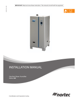
Figure 8 generalizes the eect of water hardness, and demand on cylinder life. Cylinder life is ultimately
determined by the water chemistry, the unit running time, and steam output capacity setting.
Figure 8:
0%
Average Operating Hours
Note: Other parameters may affect cylinder life.
500 1000 2000 4000 8000
5
10
20
30
Grains of Hardness
500
400
200
100
CaCO mg/L (ppm)
3
Cylinder Life Expectancy
Capacity adjustment setting
100% 50% 25%
Electrode Drain Rate vs.
Water Conductivity with
Auto-Adaptive Control
200
0
400
600
800
1000
1200
Conductivity of Water ( S/cm)μ
Total Dissolved Solids (ppm)
20% 40% 60% 80% 100%
900
800
700
600
500
400
300
200
100
0
(As a percentage of steam output)
Drain Rate
Water Conditions vs. Steam Cylinder Life and Drain Rates
/