Siemens QFM2100 Installation Instructions Manual
- Type
- Installation Instructions Manual
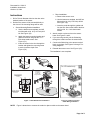
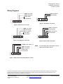
Siemens QFM2100 is a relative humidity sensor used to monitor the humidity levels in a duct. It can be directly wired to a controller using twisted pairs or three-conductor cables. The sensor has an accuracy of ±5% and a humidity signal range of 0 to 10 Vdc. It is easy to install and can be mounted directly to the duct or using a mounting flange. The sensor is suitable for use in various applications, including HVAC systems, data centers, and cleanrooms.
Siemens QFM2100 is a relative humidity sensor used to monitor the humidity levels in a duct. It can be directly wired to a controller using twisted pairs or three-conductor cables. The sensor has an accuracy of ±5% and a humidity signal range of 0 to 10 Vdc. It is easy to install and can be mounted directly to the duct or using a mounting flange. The sensor is suitable for use in various applications, including HVAC systems, data centers, and cleanrooms.


-
 1
1
-
 2
2
-
 3
3


Siemens QFM2100 Installation Instructions Manual
- Type
- Installation Instructions Manual
Siemens QFM2100 is a relative humidity sensor used to monitor the humidity levels in a duct. It can be directly wired to a controller using twisted pairs or three-conductor cables. The sensor has an accuracy of ±5% and a humidity signal range of 0 to 10 Vdc. It is easy to install and can be mounted directly to the duct or using a mounting flange. The sensor is suitable for use in various applications, including HVAC systems, data centers, and cleanrooms.
Ask a question and I''ll find the answer in the document
Finding information in a document is now easier with AI
Related papers
Other documents
-
Trane VariTrac VAV-SVN03A-EN Installation guide
-
-
-
Trane IntelliPak SIRG-020 User manual
-
Johnson Controls VMA 1410 Overview And Engineering Manuallines
-
-
-
-
Ingersoll-Rand THC120E Installation, Operation and Maintenance Manual
-