Page is loading ...

Service Guide
Alemite Corporation
PO Box 473515, Charlotte, North Carolina 28247-3515
Copyright
©
1996 by Alemite Corporation
This document contains confidential information that is the property of Alemite Corporation
396609
and is not to be copied, used, or disclosed to others without express written permission.
Revision (10-96)
SER 6320-3
6320-3
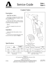
High-Pressure Control Valve
7-3/4 "
(19.7 cm)
Material
Outlet
Material Inlet
WARNING
This control valve operates on high-pressure systems.
Before attempting any service procedure, make sure all components
within the system are at zero pressure.
Never point a control valve at any portion of your body or another
person. Accidental discharge of pressure and/or material can result
in personal injury.
Do not exceed the pressure rating of any component in the system.
Read each step of the instructions carefully. Make sure a proper
understanding is achieved before proceeding.
Figure 1
High-Pressure Control Valve Model 6320-3

SER 6320-3
High-Pressure Control Valve
Revision (10-96) 2 Alemite Corporation
Accessory Item
25
26
1a
20
18
17
11
2
24
15
10
9
1
3
4
5
6
7
8
13
14
14
16
14
12
23
22
21
19
Figure 2
High-Pressure Control Valve Model 6320-3 - Exploded View

High-Pressure Control Valve
SER 6320-3
Alemite Corporation 3 Revision (10-96)
Item
No. Part No. Description Qty Notes Numeric Order
Part # (Item #)
1Setscrew, 3/8"-24 x 5/8 " 16304-B (26)
2322956 Lever and Bracket Assembly 16778 (1a)
3Plug, Packing 147064 (14)
4171001-7 O-Ring, 1/2 " OD 147069 (17)
5Washer, Back-Up, 3/16 " ID (Leather) 1
47071
(23)
6171001-3 O-Ring, 5/16 " OD 1
47073
(22)
7Washer, Lock 147074 (24)
8Screw, 5/16 "-18 x 5/8 " 147075 (20)
9322949 Support 1
47076
(21)
10 Body 147079 (15)
11 328087 Stem, Plunger 1
47081
(13)
12 47092 Washer, 0.195 " ID 147089 (19)
13 Spring, 1-1/2 " Long 147092 (12)
14 47064 Gasket (Aluminum) 3
47301
(16)
15 47079 Guide, Symmetrical 149136 (25)
16 Valve and Seat Assembly 1
76856
(7)
17 47069 Bushing 1
170595
(8)
18 322897 Adapter, Inlet, 1/4 " NPTF (f) 1171001-3 (6)
19 47089 Gasket 1171001-7 (4)
20 47075 Locknut 1322897 (18)
21 Ring, Packing, 0.69 " ID (Brass) 1322949 (9)
22 Spring, 1-9/32 " Long 1
322952
(3)
23 Valve, Single-Shot 1
322953
(5)
24 47074 Adjuster, Single-Shot 1
322954
(1)
25 49136 Extension, Rigid 1322956 (2)
26 6304-B Coupler, Hydraulic 1
322957-3
(10)
Optional Equipment
328087 (11)
1a 6778 Extension, Rigid/Flexible 1
Legend
:
Part numbers left blank (or in
italics
) are not available separately
designates a repair kit item
Repair Kit
Part No. Kit Symbol Description
398964-2
Kit, Major Repair

SER 6320-3
High-Pressure Control Valve
Revision (10-96) 4 Alemite Corporation
Description and Operation
The model 6320-3 high-pressure control valve is all steel construction. It is designed for
high pressure applications up to 7500 psi (517 Bars). The valve dispenses a variety of lubricants
from numerous types of power-operated equipment.
Modes-of-Operation
Single-Shot and Continuous Flow
WARNING
Connect the control valve to a fitting prior to operation.
High velocity discharge can result in injury to personnel.
The valve has two modes-of-operation. When the lever is partially depressed, it delivers 1/2
of a preset measured amount of product. Release the lever to complete the preset delivery.
Depress the valve lever completely and hold to provide a continuous flow of material.
Specifications
Accessories
WARNING
Altering the control valve with the addition of a flexible hose
extension is not recommended. Personal injury may occur.
If a flexible extension is mandatory, use only Alemite Corporation
extension hose number 6778.
Preventive Maintenance
Refer to section entitled
Overhaul
for details on the procedures necessary to perform
maintenance.
Material Inlet Material Outlet Maximum Operating Pressure
psi Bars
1/4 " NPTF (f) 1/8 " NPTF (f) 7500 517
Table 1
High-Pressure Control Valve Model 6320-3 Specifications
Part Number Description
6778 Rigid/Flexible Extension
Table 2
High-Pressure Control Valve Model 6320-3 Accessory
Daily Weekly Monthly Yearly
Wipe Exterior with
Clean Cloth Inspect for Leakage Adjust Lever
Table 3
High-Pressure Control Valve Model 6320-3
Preventive Maintenance Schedule

High-Pressure Control Valve
SER 6320-3
Alemite Corporation 5 Revision (10-96)
1
2
3
4
5
7
8
9
10
11
13
14
15
12
16
14
17
14
23
22
24
21
20
19
18
25
6
Overhaul
NOTE
: Refer to
Figure 2
and/or
Figure 3
for component identification on all overhaul
procedures.
Prior to performing any maintenance procedure, the
following safety precautions must be observed. Personal
injury may occur.
WARNING
Release all pressure within the system
prior to performing any overhaul procedure.
• Disconnect the air supply line from the pump
motor.
• Into an appropriate container, operate the
control valve to discharge remaining pressure
within the system.
Never point a control valve at any portion of your
body or another person. Accidental discharge of
pressure and/or material can result in personal
injury.
Read each step of the instructions carefully. Make
sure a proper understanding is achieved before
proceeding.
Removal
Remove Z-Swivel from control valve’s Inlet
Adapter (
18
).
Disassembly
Remove or Unscrew:
1. Extension (
25
) and Coupler (
26
) from Body (
10
).
2. Bushing (
17
) from the Body.
NOTE
: This separates the lower portion of
the valve from the upper portion.
Lower Portion
3. Locknut (
20)
several turns from Single-Shot
Adjuster (
24
).
4. Single-Shot Adjuster from Bushing (
17
).
5. Locknut from Single-Shot Adjuster.
Figure 3
High-Pressure Control Valve Model 6320-3
Section View
Refer to
Figure 2
Parts List
for Parts Identification

SER 6320-3
High-Pressure Control Valve
Revision (10-96) 6 Alemite Corporation
CAUTION
Do not damage any portion of Single-Shot
Adjuster (24) during removal of Packing Ring (21).
6. Packing Ring (
21
) from Single-Shot Adjuster (
24
).
7. Single-Shot Adjuster from Inlet Adapter (
18
). The Sin-
gle-Shot Adjuster is under slight spring pressure.
8. Gasket (
19
), Spring (
22
), and Single-Shot Valve (
23
)
from Single-Shot Adjuster.
Upper Portion
9. Aluminum Gasket (
14
) and Seat assembly (
16
) from
Body (
10
).
10. Additional Gaskets (
14
), Symmetrical Guide (
15
), and
Spring (
13
) from the Body.
11. Screw (
8
), Lock Washer (
7
), and Support (
9
) from
Body.
12. Lever and Bracket assembly (
2
).
13. Setscrew (
1
) from Lever and Bracket assembly.
14. Packing Plug (
3
) from the Body.
15. Plunger Stem (
11
) and Washer (
12
) from the Body.
16. O-Rings (
4
and
6
) and Back-Up Washer (
5
) from the
Packing Plug.
Clean and Inspect
NOTE
: Use a repair kit for replacement
parts. Make sure all the components are
included in the kit before discarding used
parts.
WARNING
Do not use halogenated hydrocarbon
solvents such as methylene chloride or 1,1,1-
trichlorethane in this valve. An explosion can
result when aluminum and/or zinc-plated parts
come in contact with halogenated hydrocarbon
solvents.
1. Clean all metal parts in a modified petroleum-based
solvent. The solvent should be environmentally safe.
2. Inspect all parts for wear and/or damage.
• Replace as necessary.
3. Closely inspect the mating surfaces of all components
for any imperfections Ensure a smooth and clean
contact is obtained when assembled.
EXAMPLE
: Make sure Valve and Seat
Assembly (
16
) seats properly.
4. Inspect Valve and Seat assembly (
16
), Single-Shot
Valve (
23
), and Single-Shot Adjuster (
24
) closely. Use
a magnifying glass to detect any wire draw marks.
Assembly
NOTE
: Prior to assembly, certain
components require lubrication. Refer to
Table 4
for details.
Install or Screw:
1. Lubricated Back-Up Washer (
5
) small O-Ring (
6
) into
Packing Plug (
3
).
2. Lubricated O-Ring (
4
) onto the Packing Plug.
3. Washer (
12
) onto flats end of Plunger Stem (
11
).
4. Stem and Washer assembly into the Body.
• Make sure the Washer seats properly.
5. Packing Plug assembly over the Stem and screw into
the Body.
Part # (Item #)* Description Lubricant
171001-3 (6) O-Ring, 5/16 " OD SAE 30 Oil
171001-7 (4) O-Ring, 1/2 " OD SAE 30 Oil
322953 (5) Washer, Back-Up, 3/16 " ID (Leather) Soak 8 hours at room temperature in SAE 30 Oil
* Refer to
Figure 2
Parts List for Parts Identification
Table 4
Lubrication Specifications

High-Pressure Control Valve
SER 6320-3
Alemite Corporation 7 Revision (10-96)
6. Spring (
13
) onto the Stem.
7. Aluminum crush Gasket (
14
) into the Body.
8. Symmetrical Guide (
15
) and additional Gasket (
14
).
9. Valve and Seat Assembly (
16
) and final Gasket (
14
)
into the Body.
10. Bushing (
17
) into the Body.
• While retaining Packing Plug (
3
), tighten Bushing
(
17
) securely into the Body. Tighten sufficiently to
properly crush Gaskets (
14
).
NOTE
: Make sure Plunger Stem (
11
)
extends approximately 3/8 " (9.5 mm) from
top of Body (
10
) and has spring pressure. If
no pressure is felt, Washer (
12
) is installed
incorrectly. Refer to steps 3 and 4.
11. Setscrew (
1
) into Lever and Bracket assembly (
2
).
12. Position the top of the Setscrew so one full thread on
the Lever and Bracket assembly is present.
See
Figure 2
.
13. Lever and Bracket assembly and Support (
9
) onto the
Body.
14. Lock Washer (
7
) and Screw (
8
).
• Tighten screw securely.
15. Extension (
25
) and Coupler (
26
) into the Body.
• Tighten the extension in the proper position.
CAUTION
Do not use excessive force when installing Single-
Shot Adjuster (24) into Bushing (17). Component
damage can occur.
16. Single-Shot Adjuster (
24
) into Bushing (
17
) until it
seats against the Spring and Plunger Seat
assembly (
16
).
IMPORTANT: Turn the Single-Shot Adjuster
counterclockwise 1-1/4 turns. This
adjustment approximates the setting
required for the single-shot mode-of-
operation.
17. Packing Ring (
21
) into Bushing (
17
).
18. Locknut (
20
) onto Single-Shot Adjuster (24) firmly.
• Make sure the Single-Shot Adjuster does not move
from initial setting of 1-1/4 turns.
19. Single-Shot Valve (23) and Spring (22) into the Single-
Shot Adjuster.
• Make sure the Single-Shot Valve is centered
properly.
20. Gasket (19) into the Single-Shot Adjuster.
IMPORTANT: Press downward on Inlet
Adapter (18) during installation to overcome
Spring pressure. Cross threading can occur.
21. Inlet Adapter (18) into the Single-Shot Adjuster.
• Tighten sufficiently to properly crush the Gasket.
Setscrew Adjustment (Lever Free-Play)
IMPORTANT: This setting establishes the
amount of lever travel before the single-shot
mode-of-operation takes effect.
If the clearance is too great, the continuous
mode-of-operation can be lost. Not enough
clearance can prevent the valve from shutting
off.
The setscrew should be adjusted so a 1/16 " (1.5 mm)
clearance between the bottom of the hole on Lever (2) and
the surface of Extension (25) is achieved. See Figure 4.
Figure 4 Lever Free-Play
This setting is the amount of lever free-play before
product begins to flow.
To set the clearance, adjust Setscrew (1) clockwise to
increase the amount of free-play and counterclockwise to
decrease the gap.
25
2
1
1/16 "
(1.5 mm)
Refer to Figure 2 Parts List
for Parts Identification

SER 6320-3 High-Pressure Control Valve
Revision (10-96) 8 Alemite Corporation
Installation
Attach the Z-Swivel to the control valve’s Inlet
Adapter (18). Tighten connection securely.
Operation and Adjustments
WARNING
Should leakage occur anywhere within the
system, disconnect power to the motor. Personal
injury can occur.
Prime and Test
NOTE: Perform the following procedures at
a pressure not to exceed 3000 psi (207 Bars).
Should valve leakage occur at anytime, refer
to the Troubleshooting Chart.
1. Place the pump in the product to be dispensed.
2. Point the control valve into an appropriate collection
container.
3. Connect the air line to the pump motor.
• The control valve should show no leakage or
dispense the product.
4. Depress the control valve Lever (2) fully.
• Product should flow continuously once air is
eliminated from the control valve (and system).
If the control valve does not dispense the
product, refer to the Troubleshooting
Chart.
5. Release the Lever.
If product appears at Coupler (26):
6. Turn Setscrew (1) counterclockwise until the product
discontinues to flow.
Product Delivery Adjustment (Single-Shot)
IMPORTANT: The adjustment for the single-
shot mode-of-operation effects the
continuous mode-of-operation. If the single-
shot adjustment is set too great, the
continuous mode-of-operation may be lost.
1. Depress the control valve Lever (2) partially to initiate
the single-shot mode of operation.
If product does not begin to flow or too great
(or too little) an amount is produced, adjustment is
necessary.
2. Make sure to read the following warning.
WARNING
Release all pressure within the system
prior to valve adjustment.
• Disconnect the air supply line from the pump
motor.
• Into an appropriate container, operate the
control valve to discharge remaining pressure
within the system.
Personal injury can occur.
3. Loosen Locknut (20) 1/8 turn. See Figure 5.
• Do not allow the Locknut to completely disengage
Single-Shot Adjuster (24).
Figure 5 Single-Shot Adjustment Components
WARNING
Do not turn the Single-Shot Adjuster
counterclockwise more than a total of four turns.
Personal injury can occur.
17
23
22
24
21
20
19
18
Refer to Figure 2 Parts List
for Parts Identification

High-Pressure Control Valve SER 6320-3
Alemite Corporation 9 Revision (10-96)
4. Turn the Single-Shot Adjuster 1/8 turn clockwise to
decrease delivery or counterclockwise to increase
delivery.
5. Tighten Locknut (20).
6. Connect the air line to the pump motor.
7. Depress the lever partially and observe the amount of
product dispensed.
8. If readjustment is necessary, repeat steps 2 through 5.
9. Depress the lever fully to ensure that the continuous
mode-of-operation is available.
Troubleshooting Chart
Control Valve in Static Condition or in Unattached Operation
Control Valve Indications Possible Problems Solution
Continuous product flow 1. Foreign material under Valve and Seat
Assembly (16) and/or Single-Shot Valve
(23)
2. Lever adjustment incorrect
1. Disassemble, clean, and inspect seat
areas. Check mating surfaces and
replace parts as necessary. Locate
and eliminate source of foreign
material.
2. Adjust lever free-play
No product flow
Continuous mode does not
function
Valve not adjusted properly Adjust setting.
Single-Shot mode does not
function Single-Shot Adjuster (24) not set correctly Adjust setting
Leakage at top and/or bottom of
Body (10)1. Initial tightening not sufficient
2. O-Ring (4) not sealing
3. Crush Gaskets (14) not sealing
1. Tighten Packing Plug (3) and
Bushing (17)
2. Replace O-Ring (4)
3. Replace Gaskets (14)
Leakage at Extension (25) Initial tightening not sufficient 1. Tighten Extension into
Body (10)
2. Apply Teflon tape* to Extension
threads
Leakage at rear end of
Coupler (26)Initial tightening not sufficient 1. Tighten Coupler into Extension (25)
2. Apply Teflon tape* to Extension
threads
Leakage around
Locknut (20)1. Initial tightening not sufficient
2. Packing Ring (21) not sealing 1. Tighten Locknut (20)
2. Replace Packing Ring (21)
Leakage at top or bottom of Inlet
Adapter (18)1. Initial tightening not sufficient
2. Crush Gasket (19) not sealing 1. Tighten Inlet Adapter (18)
2. Replace Gasket (19)
Leakage at Stem (11) 1. O-Ring (6) not sealing
2. Plunger Stem (11) damaged 1. Replace O-Ring (6)
2. Replace Plunger Stem (11)
Control Valve Connected to Fitting
Control Valve Indications Possible Problems Solution
Leakage at front end of
Coupler (26)1. Coupler damaged
2. Coupler to fitting mismatch
3. Foreign or damaged fitting
1. Replace Coupler (26)
2. Replace fitting and/or Coupler (26)
3. Replace with Alemite fitting
* Do not apply Teflon tape to the first two (2) threads. Contamination can occur.
Changes Since Last Printing
Added kit symbol to item 17

SER 6320-3 High-Pressure Control Valve
Revision (10-96) 10 Alemite Corporation
/