Page is loading ...

Dehumidification
The highly efficient Ultra-Aire XT whole house ventilating
dehumidifier utilizes refrigeration to cool the incoming air stream
below its dew point. This cooled and drier air is used to pre-cool
the incoming air stream resulting in a significant increase in overall
efficiency. After the pre-cooling stage, the processed air is reheated
by passing through the condenser coil. The heat removed by the
evaporator coil is returned to the air stream, resulting in an overall
temperature increase of the air leaving the unit.
The Ultra-Aire XT's are controlled by 24 volt remote wired controls.
A variety of controls are available for various applications.
Fresh Air Ventilation
Optional fresh outdoor air may be ducted to the unit via a six inch
round duct. This provides fresh air to dilute pollutants and maintain
high oxygen content in the air. The amount of fresh air ventilation
can be regulated by a variety of dampers and controls.
Air Filtration
The Ultra-Aire XT includes air filtration to improve indoor air quality.
A MERV-11 media filter is standard. An optional external
filter box with a MERV-14 deep pleated 95% media filter is
available for optimum air filtration and to reduce potentially
harmful airborne particles.
© 2007 Therma-Stor LLC • Manual P/N TS-693, 01/12
4201 Lien Rd Madison, WI 53704 • TOLL-FREE 1-800-533-7533 • www.thermastor.com • sales@thermastor.com
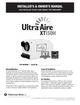
INSTALLER’S & OWNER’S MANUAL
HVAC INSTALLER: PLEASE LEAVE MANUAL FOR HOMEOWNER
P/N 4032240 (XT105H)
P/N 4031070 (XT155H)
P/N 4031560 (XT205H) • Serial No.________________________ Install Date:___________
Sold by:
XT105H XT155H XT205H
PATENTS:
D570,988
8,069,681

Table of Contents
Safety Precautions ......................................................................... 3
1. Intended Application .................................................................. 4
2. Specications ........................................................................... 4
3. Installation ................................................................................ 5
3.1 Location ............................................................................. 5
3.2 Electrical Requirements ...................................................... 5
3.3 Condensate Removal .......................................................... 6
3.4 Ducting ............................................................................... 6
3.4A Installing Duct Collars ................................................. 6
3.4B Ducting for Dehumidication ....................................... 6
3.4C Ducting for Fresh Air .................................................... 6
3.4D Installation in a Basement .......................................... 7
3.4E Installation in a attic .................................................... 7
3.4F Installation with (2) HVAC systems ............................... 8
3.4G Installation without an HVAC system ............................ 8
3.5 Quiet Installation ................................................................. 8
4. Controls .................................................................................8-9
5. DEH 3000/DEH 3000R Digital Control ..................................... 10
6. Maintenance ............................................................................ 11
6.1 Standard Air Filter ............................................................. 11
6.2 High Efciency Air Filter .................................................... 11
6.3 Impeller Fan Oiling ............................................................ 11
6.4 Fresh Air Return ............................................................... 11
7. Service .................................................................................... 11
7.1 Warranty .......................................................................... 11
7.2 Technical description ........................................................ 11
7.3 Troubleshooting ................................................................ 11
7.4 Refrigerant Charging ....................................................... 12
7.5 Impeller Fan Replacement ............................................... 12
7.6 Compressor/Capacitor Replacement ................................. 12
7.6A Checking Compressor Motor Circuits ........................ 13
7.6B Replacing Burned Out Compressor ........................... 13
7.6C Replacing Compressor-Nonburn Out.......................... 14
7.7 Remote Controls ............................................................... 14
7.7A Humidity Control ........................................................ 14
7.7B Ventilation Timer ........................................................ 14
7.8 Defrost Thermostat ........................................................... 14
7.9 Electric Ventilation Damper ............................................... 14
7.10 Condensate Pump Kit ..................................................... 14
Electrical Schematic ................................................................... 15
Service Parts List ........................................................................ 16
Optional Parts List ....................................................................... 17
Door and Collar Assembly ........................................................... 18
Warranty ...................................................................................... 19
TABLE OF CONTENTS
2Ultra-Aire XT105H, XT155H, and XT205H Installer’s & Owner’s Manual

SAFETY PRECAUTIONS
3Ultra-Aire XT105H, XT155H, and XT205H Installer’s & Owner’s Manual
Safety Precautions
Read the installation, operation and maintenance instructions
carefully before installing and operating these devices. Proper
adherence to these instructions is essential to obtain maximum
benefit from your Ultra-Aire XT indoor air quality systems.
READ AND SAVE THESE INSTRUCTIONS
• The device is designed to be installed INDOORS IN A SPACE THAT
IS PROTECTED FROM RAIN AND FLOODING.
• Install the unit with space to access the back or side panels
for maintenance and service. DO NOT INSTALL UNIT WITH THE
SERVICE PANELS INACCESSIBLE.
• Avoid directing the discharge air at people, or over the water in
pool areas.
• If used near a pool or spa; be certain there is NO chance the unit
could fall into the water, be splashed and that it is plugged into a
GFI GROUND FAULT INTERRUPT OUTLET.
• DO NOT use the device as a bench or table.
• DO NOT place the device directly on structural members. Provide
vibration isolation in order to minimize operational vibration
and/or noise.
• A drain pan MUST be placed under the unit if installed above a
living area or above an area where water leakage could cause
damage

1. Intended Application for Ultra-Aire XT Models
For the ideal installation, draw air from the central part of the home
and return it to isolated areas of the home like the bedrooms, den,
utility room, or family room. The ductwork of the existing heating
system can be used to supply air to the home.
2. Specifications
FOR HVAC INSTALLER ONLY
4Ultra-Aire XT105H, XT155H, and XT205H Installer’s & Owner’s Manual
Unit: 4032240 XT105H 4031070 XT155H 4031560 XT205H
Blower:
(Tested with duct collars on)
257 CFM @ 0.0" WG
206 CFM @ 0.2" WG
146 CFM @ 0.4" WG
391 CFM @ 0.0" WG
363 CFM @ 0.2" WG
337 CFM @ 0.4" WG
526 CFM @ 0.0" WG
495 CFM @ 0.2" WG
458 CFM @ 0.4" WG
Power: 530 Watts @ 80°F and 60% RH 920 Watts @ 80°F and 60% RH 1525 Watts @ 80°F and 60% RH
Supply voltage: 110-120 VAC - 1 Phase - 60 Hz. 110-120 VAC - 1 Phase - 60 Hz. 110-120 VAC - 1 Phase - 60 Hz.
Current Draw: 4.9 Amps 8.0 Amps 13.2 Amps
Energy Factor: 4.2 3.5 2.7
Operating Temp: 56°F Min - 95°F Max 56°F Min - 95°F Max 56°F Min - 95°F Max
Sized For: 2500 Square Foot Typical 3500 Square Foot Typical 5000 Square Foot Typical
Minimum Performance @ 80°F and 60% RH:
Water Removal:
Efciency:
105 Pints/Day
8.8 Pints/kWh
155 Pints/Day
7.3 Pints/kWh
205 Pints/Day
5.7 Pints/kWh
Duct Connections: Inlet: 10" Round Duct Collar
6" Round Duct Collar
Outlet: 10" Oval Duct Collar
Inlet: 10" Round Duct Collar
6" Round Duct Collar
Outlet: 10" Oval Duct Collar
Inlet: 10" Round Duct Collar
6" Round Duct Collar
Outlet: 10" Oval Duct Collar
Air Filter: MERV-11 Size: 16" x 20" x 2" MERV-11 Size: 16" x 20" x 2" MERV-11 Size: 16" x 20" x 2"
Power Cord: 10' 16/3 SJT w/ 5-15P Plug 10' 16/3 SJT w/ 5-15P Plug 10' 16/3 SJT w/ 5-20P Plug
*This unit requires a dedicated 20A circuit
Drain Connection: 3/4 NPT 3/4 NPT 3/4 NPT
Dimensions:
Width:
Height:
Length:
Weight:
Unit Shipping
20.25" 24"
21.75" 28.25"
38"
140 lbs 160 lbs
Unit Shipping
20.25" 24"
21.75" 28.25"
38"
140 lbs 160 lbs
Unit Shipping
20.25" 24"
21.75" 28.25"
38"
150 lbs 170 lbs
42" 42" 42"

3. Installation
3.1 Location
The Ultra-Aire XT can be installed in a variety of locations to meet
the owner's needs as listed below. In all cases keep the following
cautions in mind:
• It is designed to be installed INDOORS IN A SPACE THAT IS
PROTECTED FROM RAIN AND FLOODING.
• Install the unit with space to access the back and side panels for
maintenance and service and also to allow easy access to the filter
cover panel. DO NOT INSTALL UNIT WITH THE FRONT PANEL OR
FILTER COVER PANEL INACCESSIBLE.
• Avoid discharging the air directly at people, or over the water in pool
areas.
• If used near a pool or spa, be certain there is NO chance the unit
could fall into the water or be splashed and that it is plugged into a
GROUND FAULT INTERRUPTER.
• DO NOT use the Ultra-Aire XT as a bench or table.
• DO NOT place the Ultra-Aire XT directly on structural members.
Provide vibration isolation in order to minimize operational vibration
and/or noise.
• A drain pan MUST be placed under the unit if installed above a
living area or above an area where water leakage could cause
damage.
Place the Ultra-Aire XT on supports that raise the base of the unit
2.5" above the drain pan beneath it. Raising the Ultra-Aire XT will
help the unit drain with gravity ow. Do not place the Ultra-Aire XT
directly on structural building members without vibration absorbers
or unwanted noise may result.
The Ultra-Aire XT may be suspended with steel hanger straps
or a suitable alternative from structural members. Unit must
be supported from underneath; don't hang from sides or ends.
Remember to place a drain pan under the unit if it is suspended
above a finished area or above an area where water leakage could
cause damage.
The Ultra-Aire XT should be located near the existing HVAC system
to minimize the required ductwork for connecting the
Ultra-Aire XT to the existing air handling system. The controls for
the Ultra-Aire XT are remote from the unit and must be located in
the space that is to be conditioned. The controls are low voltage (24
volt) and should be connected to the Ultra-Aire XT with low voltage
thermostat cable.
FOR HVAC INSTALLER ONLY
5Ultra-Aire XT105H, XT155H, and XT205H Installer’s & Owner’s Manual
If fresh air ventilation is desired, thought should be given to the
location for the fresh air ducting. A 6" round insulated duct will
have to be installed on the Ultra-Aire XT and run to the outside of
the structure to bring in fresh air. Use an 8" insulated round duct
for lengths of more than 50 feet or if more than 100 CFM is needed.
Consult local codes for necessary distances from exhaust ports
when installing fresh air return.
3.2 Electrical Requirements
WARNING! DO NOT ALLOW THE YELLOW LEAD
FROM THE ULTRA-AIRE TO CONTACT THE RED LEAD OR WHITE
LEAD FROM THE ULTRA-AIRE OR THE TRANSFORMER WILL BE
DESTROYED.
The Ultra-Aire XT plugs into a common grounded outlet. The amp
draws for each unit under normal opperating condisions are listed
on page 4. If used in a wet area (or basement prone to ooding), a
ground fault interrupter protected circuit is required.
Install the remote control panel in a central area of the structure
where it will sense the relative humidity of the structure accurately.
Do not install the control panel where it may not accurately sense
the relative humidity such as near HVAC supply registers, near
exterior doors, or near a pool or spa. The installer must supply the
wiring between the Ultra-Aire XT and the control panel. Be sure to
safely route the control wiring to prevent damage during installation.
Be careful not to cross the wires when connecting the Ultra-Aire XT
and the remote control panel or damage to the transformer
may result.
The remote controls of the Ultra-Aire XT are powered by a low
voltage circuit (24 Vac) and must NEVER contact or be connected
to a high voltage circuit. The control wires leaving the Ultra-Aire XT
and the remote control panels are numbered and color-coded to
prevent confusion. Some of the control wires leaving the Ultra-Aire
XT may not be used with certain control panels and should be left
safely disconnected with wire nuts taped onto the stripped ends.
Be sure to consult the electrical schematic in this manual or inside
the access panel of the Ultra-Aire XT before making the control
connections.

3.3 Condensate Water Removal
Condensate drains by gravity via the drain port. Use 3/4" male NPT
PVC pipe. Route drain pipe to drain. Install a trap if possible. Take
care when installing drain pipe to drain port. Use an adjustable
wrench to secure the drain port. An optional condensate pump kit
may be installed if a lift is required to dispose of the condensate.
The condensate pump kit can be ordered directly from the factory.
See the optional parts list for information on the kit.
When installing the drain hose make sure the feet are extended
such that the dehumidier is 2 1/2" off the ground. Then coil the
drain hose under itself or position a spacer to lift the hose 1” off
the ground after the hose has touched the ground. This procedure
will create a trap that ensures your unit drains correctly. See the
diagram below for further visual clarification.
3.4 Ducting
3.4A Installing Duct Collars
The Ultra-Aire XT is equipped with 10" and 6" round inlet collars
and a 10" round (ovaled) exhaust collar. Follow instructions included
with collars.
3.4B Ducting for Dehumidification
For the ideal installation, draw air from the central part of the home
and return it to the isolated areas of the home like the bedrooms,
den, utility room, or family room. The ductwork of the existing
HVAC system can be used to supply air to the home. If the existing
supply goes to isolated areas of the home, discharge the supply of
the Ultra-Aire XT into the supply of the existing HVAC system. If the
existing heating system incorporates a central supply, installation
of a separate supply duct from the Ultra-Aire XT to each isolated
area is recommended. DO NOT draw air directly from the kitchen,
laundry, or isolated basement. You may draw air from a basement
that is open to the home. All flexible ducting connected to the Ultra-
Aire XT should be UL listed.
The inlet of the Ultra-Aire XT is the 10" diameter hole in the lter
enclosure of the unit. A 10" round collar is supplied with the unit
to attach to round duct. The duct may be permanently attached to
FOR HVAC INSTALLER ONLY
6Ultra-Aire XT105H, XT155H, and XT205H Installer’s & Owner’s Manual
the collar. A 6" round collar is provided with the unit to attach to
the 6" hole in the lter enclosure. The 6" collar should be capped if
fresh make-up air is not desired. If fresh make-up air is desired, see
Section 3.4C.
A 10" round (ovaled) collar is supplied with the unit for the outlet of
the Ultra-Aire XT.
A length of flexible ducting on all Ultra-Aire XT duct connections is
recommended to reduce noise and vibration transmitted to rigid
ductwork in the structure.
Ducting the Ultra-Aire XT as mentioned in Sections 3.4A-3.4G
requires consideration of the following points:
Duct Sizing: For total duct lengths up to 25', use a minimum 10"
diameter round or equivalent rectangular. For longer lengths, use a
minimum 12" diameter or equivalent. Grills or diffusers on the duct
ends must not excessively restrict airflow.
Isolated Areas: Effective dehumidication may require that ducting
be branched to isolated, stagnant areas. Use 8" or larger diameter
branch ducting to each of two or three areas, use 6" or larger to
each of four or more areas.
Connecting to existing HVAC systems: An optional 10" check
damper is available from the factory to prevent reverse flow through
the Ultra-Aire XT. If the Ultra-Aire XT is ducted to the supply ducting
of the HVAC system, it is recommended that the check damper be
placed in the Ultra-Aire XT supply duct. Contact the factory when
connecting to a static pressure of greater than or equal to +.5" WG.
3.4C Ducting for Fresh Air
Fresh air can be brought into the structure by connecting an
insulated duct from outside to the 6" Ultra-Aire XT inlet and by
turning on the fan switch or activating the humidity control (on
units with the humidity control panel). Activate the ventilation timer
on units with the ventilating and humidity control panel to bring in
fresh air. Refer to Section 7.7B for programming instructions for the
ventilation timer. Advantages of this form of ventilation include:
1. Outside air is filtered before entering the building.
2. Outside air will be dehumidified before entering if the Ultra-
Aire XT is running in dehumidification mode.
3. Drawing air from outside and blowing inside aids in slightly
pressurizing the structure. This helps prevent dirty and humid
air from entering elsewhere. It also reduces the potential for
carcinogenic radon gas to enter and provides make-up air for
open combustion and exhaust devices like the clothes drier,
fireplace, and water heater.
4. Adequate exhaust fans are recommended in the bath rooms
and kitchen.

the air supply of the existing HVAC system. A backdraft damper is
required in the duct between the 10" tee and the central supply duct
to prevent air from being discharged into the basement during central
fan operation. Connect a duct from outside to the 6" collar of the
Ultra-Aire XT if you wish to provide fresh air ventilation.
Crawl Space Installation: Install a separate return for the Ultra-
Aire XT in a central area of the structure. Duct the supply of the
Ultra-Aire XT to a 10" x 10" x 10" tee/damper that is 20% open to
the crawl space if desired. Duct the other side of the tee to the air
supply of the existing HVAC system ventilation. Connect an insulated
duct from outside to the 6" collar of the Ultra-Aire XT if you wish to
provide optional fresh air.
3.4E Installation in an Attic with an
Existing Forced Air HVAC System
ALWAYS install a catch pan with a drain and/or oat interrupt
switch for condensate under the Ultra-Aire XT in an attic to reduce
likelihood of water damage.
Locate a separate return for the Ultra-Aire XT in a central area of
the structure. Duct the supply of the Ultra-Aire XT to the air supply
of the existing HVAC system. Connect an insulated duct from
outside to the 6" collar of the Ultra-Aire XT if you wish to provide
fresh air ventilation. Adjust damper in the collar to provide the
desired amount of fresh air. Using a remote control, program the
unit to bring in the desired amount of fresh air.
Ultra-Aire
Dehumidifier
In cold climates or areas where the outdoor dew point is low
at times, ventilation can be used to dehumidify the structure.
This is accomplished by bringing the dry, low dew point air into
the structure during these times. This approach is often more
economical than running the dehumidifier to remove excess
moisture from the structure. In cold climates, it is critical to
adequately ventilate to reduce the inside moisture content to
avoid moisture accumulating in the wall cavities. For example; in a
house that experiences condensation on the interior surface of the
windows during the winter, increasing the amount of ventilation will
often cure the problem.
An insulated 6" diameter duct is generally sufcient to provide up
to 100 CFM of outside air. Large quantities of outside air will either
positively or negatively impact the performance of the Ultra-Aire
XT, depending upon inside and outside air conditions. Consult the
factory by calling 1-800-533-7533 for recommendations regarding
the use of higher flows with your specific application.
The outside air duct should be connected to the 6" round collar on
the lter enclosure of the unit. The 6" round collar includes a manual
damper. Adjust the manual damper to provide the desired amount of
fresh air for ventilation. The amount of fresh air should be based on
the size and occupancy of the residence. If you are unsure of your
ventilation air requirements, consult the factory by calling 1-800-
533-7533 for assistance or check your local building codes.
3.4D Installation in a Basement or Crawlspace
with an Existing Forced Air HVAC System
It is recommended that a new, separate return duct be installed
for the Ultra-Aire XT from a central area of the house. If this is not
possible, and if the existing system has multiple returns, select one
to disconnect from the existing forced air system and use it for the
dedicated Ultra-Aire XT return. Always select a return from a central
location in the structure in an area that is always open to the rest
of the structure. Do not use a return from a room that may have its
door closed much of the time.
If the structure in which the Ultra-Aire XT is to be installed has an
existing forced air HVAC system, utilize the HVAC system to make the
Ultra-Aire XT installation easier.
Basement Installation: Install a separate 10" return for the Ultra-
Aire XT in a central area of the structure. Duct the supply of the
Ultra-Aire XT to an optional 10" x 10" x 10" tee/damper that is 20%
open to the basement. This allows the ability to discharge a variable
amount of dehumidified air into a basement that may not be well
served by the existing duct system. Duct the other side of the tee to
FOR HVAC INSTALLER ONLY
7Ultra-Aire XT105H, XT155H, and XT205H Installer’s & Owner’s Manual

8Ultra-Aire XT105H, XT155H, and XT205H Installer’s & Owner’s Manual
3.4F Installation in a Structure with
Two Forced Air HVAC Systems
The Ultra-Aire XT can be installed into two typical HVAC ducting
systems. Install a separate return for the Ultra-Aire XT as directed
above. Discharge air from the dehumidier should be split and
routed to each supply ducting system. A balancing damper and
a backdraft damper is required in each duct between the Ultra-
Aire XT and the HVAC ducting system. This allows airflow to be
adjusted and prevents flow of air between the ducting systems.
Contact the factory for assistance, if necessary.
3.4G Installation in a Structure with No Existing
Forced Air HVAC System
When installing the Ultra-Aire XT in a structure that does not
have a forced air HVAC system, a single return for the Ultra-Aire
XT should be installed in central open area of the structure. DO
NOT locate the return in a bathroom or a kitchen. The supply of
the Ultra-Aire XT should be located in the remote areas of the
structure (such as bedrooms, den, etc.). By ducting this way, the
air inside the structure will circulate through the Ultra-Aire XT to
be filtered and dehumidified. Avoid discharging all the air from the
dehumidifier in one location to prevent heat build up in that area.
4" diameter duct is recommended for branches to the bedrooms,
6" diameter duct is recommended for branches to larger areas.
Refer to section 3.4B for branch duct sizing. Connect an insulated
duct from outside to the 6" collar of the Ultra-Aire XT if you wish to
provide fresh air ventilation.
3.5 Quiet Installation
Consider compression vibration and airflow noise during
installation. Use of flex duct and/or vibration isolation materials
during mounting and ducting will result in quieter operation.
A length of flexible ducting on all Ultra-Aire XT duct connections is
recommended to reduce noise and vibration transmitted to rigid
ductwork in the structure.
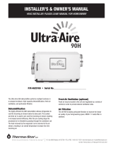
(P/N 4028539; with remote: P/N 4028407)
Ultra-Aire
Dehumidifier
RED
YELLOW
BLUE
GREEN or BROWN
WHITE
Internal Connections
OPTIONAL
DAMPER
24 VAC
DMP COMP FAN
FOR HVAC INSTALLER ONLY
4. Controls
The Ultra-Aire can be equipped with various accessories to
enhance its operation. A remote control must be used with the
Ultra-Aire. Therma-Stor offers the DEH 3000 proprietary controller.
The DEH 3000 allows homeowners the ability to monitor and
control relative humidity levels in their home. This control is also
offered with a remote sensing option.
WARNING: DO NOT allow the yellow lead from
the unit to contact the red lead or the white lead
from the unit or damage to the transformers will
result.
The UA dehumidifier is controlled using five color-coded wires.
Green (or brown) = Fan control
Blue = Dehumidication (fan and compressor) control
Red = 24volt AC power transformer neutral side (common with white)
White = 24volt AC power transformer neutral side (common with red)
Yellow = transformer high side
Between the red/white lead and the yellow leads is a 40VA trans-
former. This low voltage power source powers the relay coils which
control the fan and compressors. This 24VAC transformer can also
be used to power HVAC assessories external to the dehumidifier.
• To turn the dehumidifier ON, make contact between yellow and
blue wires.
• To turn the fan ON, make contact between yellow and green(or
brown) wires.
• To power an HVAC accessory, connect the accessory to the
white (or red) wire and the yellow wire.
Ultra-Aire
Dehumidifier

ATTENTION INSTALLER
9Ultra-Aire XT105H, XT155H, and XT205H Installer’s & Owner’s Manual
Ultra-Aire
Dehumidifier
RED
4201 Lien Rd. Madison, WI 53704 • TOLL-FREE 1-800-533-7533 • www.thermastor.com • sales@thermastor.com
TS-234, 11/09
WARNING: Allowing yellow wire to contact red or white wire
will destroy the transformer.
Dehumidifier on : Connect yellow and blue wires.
Fan only on : Connect yellow and green (or brown) wires.
Accessory power : 24volt AC power supply available for HVAC accessories between yellow and
white(and/or red) wire. Red and white wires are common with each other.
Ultra-Aire DEH 3000 dehumidification & ventilation control
YELLOW
BLUE
GREEN or BROWN
WHITE
Internal Connections
OPTIONAL
DAMPER
24 VAC
DMP COMP FAN
(P/N 4028539; with remote: P/N 4028407)

10 Ultra-Aire XT105H, XT155H, and XT205H Installer’s & Owner’s Manual
5. Optional Dehumidifier & Ventilation
System Controller
When used with Ultra-Aire Whole House Ventilating
Dehumidiers, the DEH 3000/3000R allows homeowners the
ability to monitor and control relative humidity levels in their
home.
DEH3000 P/N: 4028539
DEH3000R (remote) P/N: 4028407
Model: DEH 3000
DEH 3000R (remote)
Operating Voltage: 24 VAC
Max Current
DMP, COMP, FAN: 1 AMP each
Humidity Range/Accuracy: 10 – 95% RH,
±
5%
Humidity Setpoint 35% min – 70% max
Auxillary Relay Capacity: 5 Amps, 24VAC
Temp Range/Accuracy: 30°-90°F,
±
2°F
Size: 4.95"L x 1.06"W x 4.19"H
Major Operations
n Digital control of Relative Humidity (Digital Set-Point)
n Fan/Filter Operation
n Programmable Ventilation Timer
n Large, easy-to-read backlit LCD display
n Easy interaction with air handler fan (Interlock/Lockout)
n High Temperature Cut-Out
n Dryout Cycle Timer
n Auto Reboot
n Remote Sensor (DEH 3000R Only)
To order call Therma-Stor
at 1-800-533-7533 or
Contact your local distributor
or HVAC contractor.
DEH 3000, DEH 3000R DEHUMIDIFIER & VENTILATION SYSTEM CONTROLLER
DEH 3000/DEH 3000R
DEH 3000/DEH 3000R
Part No. 4028539 Part No. 4028407


FOR HVAC INSTALLER ONLY
15 Ultra-Aire XT105H, XT155H, and XT205H Installer’s & Owner’s Manual
Electric Schematics of the Ultra-Aire XT
N.O.
WHT 4
UNIT
COMPRESSO
R
E-BOX
1
59
14 13
WHT 4
BLK 1
8
2
3
2
2
2
3
7
5
COMCOM
115V 24V
WHT 6
BLU 7
YEL 6
RED 1
GRN 5
RED 6
5
WHT 6
BLU 2
BLU 2
BLK 1
BRN 3
GRN 4
GRN 4
GRN 9
BLOWER CAPACITOR
BLU 7
YEL 6
RED 1
WHT 4
GRN 5
MAKE SURE WIRE IS
CAPPED IF DAMPER
IS NOT USED

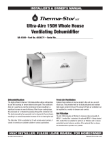
Item Part No Qty Description
1 4021475 1 Air Filter 16x20x2" MERV-11
2 4026221 4 Foot, Leveling, 5/16-18
3 4031085 1 Condenser Coil
4 4031086 1 (XT105 & XT155) Evaporator Coil
4 4031575 1 (XT205) E-coat Evaporator Coil
5 4029510 1 Filter/Drier
6 4025741 1 Thermostat, Defrost Control
7 4032226 1 (XT105) Compressor Replacement Kit
7 4032225 1 (XT155) Compressor Replacement Kit
7 4032224 1 (XT205) Compressor Replacement Kit
4029568 1 (XT105) Compressor Overload NOT SHOWN
4029714 1 (XT155) Compressor Overload NOT SHOWN
4031574 1 (XT205) Compressor Overload
LOCATED IN COMPRESSOR CAP
Item Part No Qty Description
8 4032196 1 (XT105) Impeller
8 4026657 1 (XT155) Impeller
8 4031089 1 (XT205) Impeller
9 4031917 1 (XT105) Compressor Capacitor,
35 MFD, 370V, Oil
9 4026687 1 (XT155 & XT205) Compressor Capacitor, Run,
45 MFD, 370V
10 4031924 1 (XT105) Blower Capacitor, Run, 5 MFD, 370V, Dry
10 4032001 1 (XT155) Blower Capacitor, Run, 15 MFD, 370V
10 4032002 1 (XT205) Blower Capacitor, Run,
20 MFD, 370V, Dry
11 4020924 1 Blower Relay, SPDT, 24V, 15A
12 4022484 1 Compressor Relay, SPST, 24V, 30A
13 4022487 1 XFMR, 120V, 60Hz, 24V, 40VA
SERVICE PARTS LIST: Ultra-Aire XT
16 Ultra-Aire XT105H, XT155H, and XT205H Installer’s & Owner’s Manual
1
2
34567
8
9
10
11
12
13

17 Ultra-Aire XT105H, XT155H, and XT205H Installer’s & Owner’s Manual
OPTIONAL PARTS LIST: Ultra-Aire XT
PART NO. QTY. DESCRIPTION
4024375 1 Check Damper, 10" Diameter
4028614 1 Condensate Pump Kit, External
4023672 1 Duct Damper, 6" Diameter, Electrically Actuated
4025560 1 Switch, Black, SPDT, On/Off
4024369 1 Merv 11 Standard Filter 20" x 16 "x 2"
4032221 1 Filter Box (Needed when MERV 14 lter is used)
4028539 1 DEH 3000 Digital Controller
4028407 1 DEH 3000R Digital Controller
4028399 1 10" Oval to Round Adapter

DOOR AND COLLAR ASSEMBLY
Door Install
Insert tab on the bottom of the door,
in between the foam installation and
the metal side.
Push down on the plastic door latch
and swing door shut. Once the door is
shut release the door latch.
Collar Install
Remove the 2 round ducts, oval duct seal and
small bag of mounting hardware from inside the
rectangle opening.
Adhere seal onto the back of oval duct and mount
the ducts to the front of the dehumidifier using
screws provided.
Collars and hardware
are located here.
18 Ultra-Aire XT105H, XT155H, and XT205H Installer’s & Owner’s Manual

19
Limited Warranty
Ultra-Aire XT105H, XT155H, and XT205H Installer’s & Owner’s Manual
Limited Warranty. Therma-Stor, LLC (“Therma-Stor”) warrants
as follows: (i) the Ultra-Aire XT dehumidifier (“Product”) will be free
of material defects in workmanship or materials for a period of one
(1) year (“One-Year Warranty”) following the date of initial purchase
of such Product by an original customer purchasing from Therma-
Stor or an authorized reseller (“Customer”); and (ii) the Product’s
condenser, evaporator, and compressor will be free of material
defects in workmanship or materials for a period of five (5) years
following the date of initial purchase of such Product by a Customer.
Limitation of Remedies. CUSTOMER’S SOLE AND EXCLUSIVE
REMEDY UNDER THE ABOVE LIMITED WARRANTY AND THERMA-
STOR’S ENTIRE LIABILITY THEREUNDER, SHALL BE, AT THE SOLE
OPTION OF THERMA-STOR, REPLACEMENT OR REPAIR OF SUCH
PRODUCT OR ITS COMPONENTS (“COMPONENTS”) BY THERMA-
STOR OR THERMA-STOR’S AGENTS ONLY. REFRIGERANT, PIPING,
SUPPLIES, TRANSPORTATION COSTS, LABOR COSTS INCURRED
IN REPAIR OR REPLACEMENT OF SUCH COMPONENTS ARE NOT
INCLUDED. THIS DISCLAIMER AND EXCLUSION SHALL APPLY
EVEN IF THE EXPRESS WARRANTY AND LIMITED REMEDY SET
FORTH HEREIN FAILS OF ITS ESSENTIAL PURPOSE. CUSTOMER
ACKNOWLEDGES THAT NO REPRESENTATIVE OF THERMA-STOR OR
OF ITS AFFILIATES OR RESELLERS IS AUTHORIZED TO MAKE ANY
REPRESENTATION OR WARRANTY ON BEHALF OF THERMA-STOR
OR ANY OF ITS AFFILIATES OR RESELLERS THAT IS NOT IN THIS
AGREEMENT. Notwithstanding the above, during the term of the
One-Year Warranty only, Therma-Stor will provide, free of charge to
Customer, all Components and labor (except costs related to removal
and installation of Product) required to fulfill its obligations under such
One-Year Warranty.
Disclaimer of Warranties. EXCEPT FOR ABOVE LIMITED
WARRANTY, WHICH IS THE SOLE AND EXCLUSIVE WARRANTY
PROVIDED WITH RESPECT TO THE PRODUCT AND ITS COMPONENTS,
THERMA-STOR HEREBY DISCLAIMS ALL EXPRESS AND IMPLIED
WARRANTIES, INCLUDING, WITHOUT LIMITATION, THE IMPLIED
WARRANTIES OF MERCHANTABILITY AND FITNESS FOR A
PARTICULAR PURPOSE.
Warranty Limitations. The foregoing limited warranty extends only
to a Customer and shall be null and void upon attempted assignment
or transfer. A “defect” under the terms of the limited warranty shall
not include problems resulting from Customer’s or Customer’s
employees’, agents’, invitees’ or a third party’s misuse, improper
installation, improper design of any system in which the Product
is included, abuse, lack of normal care, failure to follow written
instructions, tampering, improper repair, or freezing, corrosion, acts
of nature or other causes not arising out of defects in Therma-Stor’s
workmanship or material. If a Product or Component is replaced
while under warranty, the applicable limited warranty period shall
not be extended beyond the original warranty time period. The
limited warranty does not cover any costs related to changes to a
Product or Component that may be required by any codes, laws, or
regulations that may become effective after initial purchase of the
Product by Customer.
Customer Responsibilities. As a further condition to obtaining
warranty coverage hereunder, the Customer must send a valid
warranty claim to Therma-Stor such that Therma-Stor receives
such claim prior to the end of the applicable warranty period.
Therma-Stor shall have no obligation hereunder with respect to
any claim received by Therma-Stor after the expiration of the
applicable warranty period. As a further condition to obtaining
warranty coverage hereunder, the Customer must present forms of
invoices evidencing proof of purchase of a Product. If such invoices
do not clearly indicate the date of initial purchase by a Customer,
the applicable Product’s date of manufacture will be used instead
of the date of initial purchase for the purpose of calculating the
commencement of the applicable warranty period. Warranty service
must be performed by Therma-Stor or a servicer authorized by
Therma-Stor. In order to obtain warranty service, the Customer
should call Therma-Stor at 1-800-533-7533 and ask for the
Therma-Stor Products Service Department, which will then arrange
for applicable warranty service. Warranty service will be performed
during customary, daytime working hours. If the Product must be
shipped for service, Customer shall be solely responsible for properly
packaging the Product, for all freight charges, and for all risk of loss
associated with shipment.
Limitation of Liability. IN NO EVENT SHALL THERMA-STOR,
IN CONNECTION WITH THE DESIGN, SALE, INSTALLATION, USE,
REPAIR, REPLACEMENT OR PERFORMANCE OF ANY PRODUCT,
COMPONENT, PART THEREOF OR WRITTEN MATERIAL PROVIDED
THEREWITH, BE LIABLE, TO THE EXTENT ALLOWED UNDER
APPLICABLE LAW, UNDER ANY LEGAL THEORY FOR ANY SPECIAL,
DIRECT, INDIRECT, COLLATERAL OR CONSEQUENTIAL DAMAGES
OF ANY KIND. NOTWITHSTANDING THE ABOVE LIMITATIONS AND
WARRANTIES, THE SOLE AND EXCLUSIVE LIABILITY OF THERMA-
STOR, REGARDLESS OF THE NATURE OR THEORY OF THE CLAIM,
SHALL UNDER NO CIRCUMSTANCES EXCEED THE PURCHASE PRICE
OF THE PRODUCT, COMPONENT OR PART UPON WHICH THE CLAIM
IS PREMISED.
Applicable Law and Venue. ANY ARBITRATION, ENFORCEMENT
OF AN ARBITRATION OR LITIGATION RELATED TO THE PRODUCT
WILL BE BROUGHT EXCLUSIVELY IN DANE COUNTY, WISCONSIN,
AND CUSTOMER CONSENTS TO THE JURISDICTION OF THE
FEDERAL AND STATE COURTS LOCATED THEREIN, SUBMITS TO
THE JURISDICTION THEREOF AND WAIVES THE RIGHT TO CHANGE
VENUE. CUSTOMER FURTHER CONSENTS TO THE EXERCISE OF
PERSONAL JURISDICTION BY ANY SUCH COURT WITH RESPECT TO
ANY SUCH PROCEEDING.
Miscellaneous. If any term or condition of this Limited Warranty
is found by a court of competent jurisdiction to be invalid, illegal or
otherwise unenforceable, the same shall not affect the other terms
or conditions hereof or thereof or the whole of this Limited Warranty.
Any delay or failure by Therma-Stor to exercise any right or remedy
will not constitute a waiver of Therma-Stor to thereafter enforce
such rights.
XT105H XT155H XT205H

/