Page is loading ...

BOX L DC1D
UNIVERSAL MOTOR CONTROLLER
For one motor doors at 24 VDC
INSTRUCTIONS MANUAL
innovative in electronics
#

INDEX
Description ............................................. 2
Limitations on the use of
motor controllers ................................. 2
Warnings ................................................. 2
Installation ............................................... 3
Important safety instructions
for installation ........................................ 3
Important safety instructions
for usage .................................................. 3
Wiring ...................................................... 4
Setup ........................................................ 6
Door types .............................................. 7
Operating modes ................................. 7
Normal functionality of securities .. 7
Electrical wiring diagram .................. 8
Photocell power wiring....................... 8
Accesories and peripherals .............. 9
Learning maneuver ............................. 10
Options .................................................... 11
Timings ..................................................... 12
Maintenance ............................................ 13
Force diagram ........................................ 13
Warranty .................................................. 14
Waste of electrical and electronic
devices ..........……...................................... 14
Features .................................................... 15
CE declaration of conformity ........... 15
Notes .......................................................... 16
Error messages ...................................... 16
Parts explosion ...................................... 17
COMPONENTS SITUATION
10
1
2
4
5
6
7
89
3
1. VDC power fuse
2. Box cover LED terminal
3. TRSH radio card slot
4. Conguration keyboard
5. TEST start button
6. Terminal strip
7. Battery fuse
8. DC motor terminal strip
9. Power input terminal strip
10. Power fuse
11. High voltage zone
12. Semaphore card slot
13. Earth fast-on terminal
14. Toroidal power transformer
......................................DC Motor
...........................Encoder pulses
....................................Flash lamp
...................................Electrolock
.................................Safety edge
............Normaly close contact
............Normaly open contact
..............................................Earth
....................High voltage zone
Simbols
Fig.1
ESPAÑOLPORTUGÊSDEUTSCH
NEDERLANDS
ITALIANO
ENGLISHFRANÇAIS
11
12
13
14
1

ESPAÑOLPORTUGÊSDEUTSCH
NEDERLANDS
ITALIANO
ENGLISHFRANÇAIS
The BXL-DC1D universal motor
controller is designed to be part of a
gate automation system for swing,
rising, sliding, or overhead gates of one
electromechanical 24VDC engine.
Among other features the motor
controller provides:
- Control 1 motor of 24VDC - 120W max.
- Automatic activation of the motor
relays and lights without spark.
- Independent connection terminals for
motor and encoder.
- Independent regulation of the power
applied to the motor both in startup,
maneuver and stop.
- Quick maneuver learning to ease
installation.
- Limit switches control.
- Independent terminals for light barrier
and safety edge with safety test option
conforming to regulations.
- Connection to electric lock, garage
light (impulsive or latched) and beacon
light.
- Two independent key inputs for
complete and pedestrian maneuvers.
- Connection sockets for radio card and
SMINN semaphore card.
- Status LEDs for all the inputs and
outputs.
- Peripheral power output with
resettable fuse.
- Optocoupled inputs with high electrical
insulation.
- Intuitive menu using a keyboard and
LCD that eases the conguration and
maintenance of the panel.
- Ability to protect the conguration
with a password.
- Storage of the number of maneuvers
and security failures to ease the
maintenance.
FEATURES
MOTOR CONTROLLER USAGE
RESTRICTIONS
Operation is not guaranteed when
installed in dierent equipment than
the specied.
The manufacturer reserves the right
to change the specications of these
systems as well as this manual
without prior warning. The equipment
must be manipulated only by
specialized and/or skilled personnel.
WARNING
This product must be used in
installations which has been
conceived for, considering any other
as improper use. The packaging must
not be dumped in the environment.
Keep products, packaging, wrapping,
documentation, etc., out of the reach
of children.
Follow the current local, national or
European regulations. The
information contained in this
document may have some mistakes
that will be corrected in future
editions. The manufacturer reserves
the right to modify the contents of
this document or the product without
any prior warning.
THE USAGE INSTRUCTIONS OF THIS DEVICE SHALL BE HANDED TO THE USER, WHO WILL
HAVE THEM IN THEIR POSSESSION. IF THEY ARE MISLAID, THE USER CAN ASK FOR A COPY
O R D O W N L O A D I T D I R E C T L Y F R O M T H E W E B S I T E W W W . S M I N N . C O M
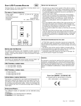
The motor controller is xed to the
wall with just 3 screws, all of them
external. See g.3
Make three holes in the wall following
the printed cutout template at the
bottom of the cardboard box.
Cut the cable glands located at the
bottom of the case and pass through
them the wiring tube inside the case.
See the IMPORTANT SAFETY
INSTRUCTIONS FOR INSTALLATION.
Connect the power supply, motor and
device cables to the terminals of the
terminal strip as indicated in the
printed circuit board. See g 1.
After activating the power supply, the
ON led will switch on . See g.1
Set up the timings and conguration
of the board.
IMPORTANT SAFETY INSTRUCTIONS
FOR INSTALLATIONS
Before installing the panel you should:
- Check that the door/shutter is in
good mechanical condition and
well balanced.
- Remove from the surroundings
anything that is not needed and
turn o AC power (VAC).
- Install the motor controller at a
minimum height of 1,5m,
preferably next to the door.
- Use power and motor cables of
enough gauge.
- Power the board through a circuit
breaker or security switch that can
be easily reached by the end user.
The European regulations for doors
EN 12453 and EN 12445 specify the
minimum protection and safety levels
for doors installed in houses and
community and public facilities.
Collision with any object must be
prevented or the contact force must
be limited (safety edge), and in the
case of automatic cycle, a presence
detector must be used too (i.e. light
barrier).
With the LED associated to each one
of these inputs.
Check that the limit switches, and if
installed, the light barrier and the safety
edge, are all working. See g. 1
Make sure the safety edge is not
activated when the door/shutter is fully
closed.
Press the TEST button (g.1) to start an
opening maneuver. If the motor doesn´t
move its conection could be reversed.
Correct it and repeat this step.
SMINN MOTOR CONTROLLERS ARE
EQUIPPED WITH A LED TO LET KNOW IF
T H E D E V I C E I S P O W E R E D .
IMPORTANT SAFETY INSTRUCTIONS
FOR USAGE
Once the controller is installed, as a
prevention measure, the user must:
- Keep the controller out of reach of
children.
- Observe that there are no objects or
people in the way when the gate is
moving.
- You must take precautions when
handling the gate manually
(unblocked) because it can move
without control, due to its own weight,
the state of xing points, springs and
counterweights.
If you detect a malfunction of the
system, call IMMEDIATELY the technical
service. You must not use the
mechanism as it can cause damage.
INSTALLATION
2
3

ESPAÑOLPORTUGÊSDEUTSCH
NEDERLANDS
ITALIANO
ENGLISHFRANÇAIS
The BXL-DC1D universal motor
controller is designed to be part of a
gate automation system for swing,
rising, sliding, or overhead gates of one
electromechanical 24VDC engine.
Among other features the motor
controller provides:
- Control 1 motor of 24VDC - 120W max.
- Automatic activation of the motor
relays and lights without spark.
- Independent connection terminals for
motor and encoder.
- Independent regulation of the power
applied to the motor both in startup,
maneuver and stop.
- Quick maneuver learning to ease
installation.
- Limit switches control.
- Independent terminals for light barrier
and safety edge with safety test option
conforming to regulations.
- Connection to electric lock, garage
light (impulsive or latched) and beacon
light.
- Two independent key inputs for
complete and pedestrian maneuvers.
- Connection sockets for radio card and
SMINN semaphore card.
- Status LEDs for all the inputs and
outputs.
- Peripheral power output with
resettable fuse.
- Optocoupled inputs with high electrical
insulation.
- Intuitive menu using a keyboard and
LCD that eases the conguration and
maintenance of the panel.
- Ability to protect the conguration
with a password.
- Storage of the number of maneuvers
and security failures to ease the
maintenance.
FEATURES
MOTOR CONTROLLER USAGE
RESTRICTIONS
Operation is not guaranteed when
installed in dierent equipment than
the specied.
The manufacturer reserves the right
to change the specications of these
systems as well as this manual
without prior warning. The equipment
must be manipulated only by
specialized and/or skilled personnel.
WARNING
This product must be used in
installations which has been
conceived for, considering any other
as improper use. The packaging must
not be dumped in the environment.
Keep products, packaging, wrapping,
documentation, etc., out of the reach
of children.
Follow the current local, national or
European regulations. The
information contained in this
document may have some mistakes
that will be corrected in future
editions. The manufacturer reserves
the right to modify the contents of
this document or the product without
any prior warning.
THE USAGE INSTRUCTIONS OF THIS DEVICE SHALL BE HANDED TO THE USER, WHO WILL
HAVE THEM IN THEIR POSSESSION. IF THEY ARE MISLAID, THE USER CAN ASK FOR A COPY
O R D O W N L O A D I T D I R E C T L Y F R O M T H E W E B S I T E W W W . S M I N N . C O M
The motor controller is xed to the
wall with just 3 screws, all of them
external. See g.3
Make three holes in the wall following
the printed cutout template at the
bottom of the cardboard box.
Cut the cable glands located at the
bottom of the case and pass through
them the wiring tube inside the case.
See the IMPORTANT SAFETY
INSTRUCTIONS FOR INSTALLATION.
Connect the power supply, motor and
device cables to the terminals of the
terminal strip as indicated in the
printed circuit board. See g 1.
After activating the power supply, the
ON led will switch on . See g.1
Set up the timings and conguration
of the board.
IMPORTANT SAFETY INSTRUCTIONS
FOR INSTALLATIONS
Before installing the panel you should:
- Check that the door/shutter is in
good mechanical condition and
well balanced.
- Remove from the surroundings
anything that is not needed and
turn o AC power (VAC).
- Install the motor controller at a
minimum height of 1,5m,
preferably next to the door.
- Use power and motor cables of
enough gauge.
- Power the board through a circuit
breaker or security switch that can
be easily reached by the end user.
The European regulations for doors
EN 12453 and EN 12445 specify the
minimum protection and safety levels
for doors installed in houses and
community and public facilities.
Collision with any object must be
prevented or the contact force must
be limited (safety edge), and in the
case of automatic cycle, a presence
detector must be used too (i.e. light
barrier).
With the LED associated to each one
of these inputs.
Check that the limit switches, and if
installed, the light barrier and the safety
edge, are all working. See g. 1
Make sure the safety edge is not
activated when the door/shutter is fully
closed.
Press the TEST button (g.1) to start an
opening maneuver. If the motor doesn´t
move its conection could be reversed.
Correct it and repeat this step.
SMINN MOTOR CONTROLLERS ARE
EQUIPPED WITH A LED TO LET KNOW IF
T H E D E V I C E I S P O W E R E D .
IMPORTANT SAFETY INSTRUCTIONS
FOR USAGE
Once the controller is installed, as a
prevention measure, the user must:
- Keep the controller out of reach of
children.
- Observe that there are no objects or
people in the way when the gate is
moving.
- You must take precautions when
handling the gate manually
(unblocked) because it can move
without control, due to its own weight,
the state of xing points, springs and
counterweights.
If you detect a malfunction of the
system, call IMMEDIATELY the technical
service. You must not use the
mechanism as it can cause damage.
INSTALLATION
2
3

The motor controller is powered with
230VAC 50Hz through terminals 1 and 2
and the ground connection is made in
the FAST-ON connector located at the
top left of the motor controller, marked
EARTH.
If desired, connect a 230VAC – 40W
lamp in the terminals 3-4 to act as a
maneuver beacon.
It is also possible to activate the garage
light or turn on a temporization device
using the terminals 5-6.
The motor controller can handle an
24DC electromechanical with encoder.
The 7 and 8 terminals are used for motor
connection.
Term. 9: Encoder 5V power
Term. 10: Encoder pulses
Term. 11: Encoder power ground
Note: If the motor has no encoder the
terminals 9, 10 and 11 will be left
disconected.
Use the terminals 12-13 to connect a
12V/24VDC - 1A electric lock. The
controller can be set to activate the
lock when opening and has options
like “Reversing stroke” and “Final
stroke”.
Terminals 14 and 15 are used to
connect an optional 24V battery (or 2
12V batteries in series) for emergency
maneuver. This connection will
charge the battery with up to 150mA.
The board has a peripheral power
output of 15VDC – 3,5VA in the
terminals 16 and 17 protected with a
resettable fuse designed to power
devices like light barriers. Also,
terminal 18 is used as an specic
negative for light barrier test.
According to regulations.
CONNECTIONS
The board has specic inputs for
opening and closing limit switches.
The contacts are normally closed and
have a shared common to ease
installation.
It is possible to install an emergency
stop button breaking both limit
switches at the same time.
See options menu.
The controller can manage light
barriers and a safety edge. The safety
edge input can be set to manage a
second light barrier or any kind of
safety edge (resistive or contact).
Light barriers must always be
normally closed. See options.
Use the terminals 25-26 to connect a
switch that starts a complete maneuver
and the terminals 26-27 to connect
another switch for pedestrian manuever
or closing.
The radio socket can be used to connect
an SMINN radio card, allowing the
controller to be used with radio
transmitters.
The semaphore card socket allows the
board to manage, via an SMINN
semaphore card, a two light semaphore
and optionally use the red light as a
maneuver beacon.
ESPAÑOLPORTUGÊSDEUTSCH
NEDERLANDS
ITALIANO
ENGLISHFRANÇAIS
Optional L.S.
EMERGENCY
STOP
4
5

CONFIGURATION MENUS
OPTIONS
Automatic closing
Fast beam closing
Optional Automatic
Invert on Key
Partial times
Limit switches
Light Barrier / Light Barrier Test
Light Barrier Mode
Band type
Band mode
Pressure Mode
Hardware short-circuit
Electrolock Type
Soft stop enabled
Close on boot
Flashing semaphore
Auxiliary dead-man
Encoder / Time Encoder
Limit switch Stop
Switch 1 / Switch 2 lock
ADJUSTMENTS
Opening time / Pedestrian
Closing time / Pedestrian
Extra time
Automatic closing / pedestrian
Close on beam
Direc. change time / inversion
Electrolock / reverse stroke
Power
Soft stop
Final stroke time
Preashing / Garage light
Pressure sensibility
Pressure limit
Overcurrent limit
MAINTENANCE
Version
Partial / Total counter
Input status
Open / Close
Default values
Enable / Change password
PROGRAMMING WIZARD
ESPAÑOLPORTUGÊSDEUTSCH
NEDERLANDS
ITALIANO
ENGLISHFRANÇAIS
SMINN
BOXL DC1D
BACK
ENTER
BACK
ENTER
The controller has an advanced menu
system using an integrated keyboard
and backlit LCD display to make
conguration and maintenance easy,
fast and intuitive.
Press the BACK and ENTER keys
simultaneously to access the
conguration menu. The LCD backlight
will power on.
There are 4 keys to move through the
menu:
BACK (exit)
ENTER (accept)
<- (back)
-> (forward)
The <- / -> keys, are used to move
through the selected menu options or
settings.
The ENTER key is used to accept and
validate the selection.
The controller has a conguration
wizard that allows the installer to set up
the most important conguration
parameters and get the board working
faster.
To use the wizard, go into the main
menu pressing BACK + ENTER,
press → until “MANEUVER PROG” is
shown in the screen and accept pressing
ENTER.
After this, the controller will ask one by
one the most important conguration
parameters to the installer. Please
choose the appropiate settings using
← and → and press ENTER to continue
or BACK to go back.
Once the needed conguration is done,
the controller will prompt the installer to
press ENTER to start the learning
maneuver.
From here on the ENTER key, the LL1
input or a radio transmitter can be used
for the learning process.
CONFIGURATION
The controller can be set up for four
dierent kind of gates.
.
- SWING
.
- RISING (Vertical)
- OVERHEAD
.
- SLIDING
.
.
OPERATING MODES
.
In all the modes securities worked as
shown in the attached chart except
when indicated otherwise.
The STOP input stops instantaneously
the maneuver.
.
STANDARD
In this mode LL1 and radio starts a full
maneuver and LL2 starts a pedestrian
maneuver. It is not possible to
interrupt the opening in this mode.
.
OPEN/CLOSE
In this mode LL1 opens and LL2
closes. Any of these signals interrupt
the current maneuver immediately.
.
ALTERNATING STOP
In this mode LL1 and radio starts a full
maneuver and LL2 starts a pedestrian
maneuver. It is possible to interrupt
the maneuver using any of these
inputs; when the gate is moving any
input will make it stop, when it is
stopped any input will make in go the
other way.
.
DEAD MAN
This mode only allows the gate to
move while the LL1 input or radio are
active (open) or the LL2 input is
active (close). The maneuver
interrupts immediately when there is
no active input.
In this mode securities only pause the
maneuver.
.
SEMIAUTOMATIC DEAD MAN
The gate opens fully when the LL1
input or radio are active but only
allows closing while the LL2 input is
kept active. Securities function
normally while opening and only
pause while closing.
DOOR TYPES
NORMAL FUNCTIONALITY OF
SECURITIES
CLOSING LIGHT BARRIER
Closing: Inverts the maneuver
Opening: Nothing
CLOSING SAFETY EDGE
Closing: Inverts 3 seconds and stops
Opening: Stops immediately
OPENING LIGHT BARRIER
Closing: Inverts the maneuver
Opening: Pauses the maneuver
OPENING SAFETY EDGE
Closing: Stops the maneuver.
Opening: Inverts 3 seconds and stops
After STOP or a safety edge collision
the next maneuver inverts direction.
6
7

pagina central
ELECTRICAL
CONNECTIONS
ACCESORIES
AND PERIPHERALS
1
230VAC phase
2
230VAC Neutral
3
Beacon light 230V 40W
4
5
POTENTIAL FREE relay contacts
for garage light or auxiliary lamp.
6
7
Motor Connection 24VDC
8
9
+ Encoder power
10
Encoder signal
11
- Encoder power
12
Electrolock 12/24 VDC
13
14
+ Battery
24VDC
15
- Battery
16
Positive
VDC power for light
barriers and other
peripherals
17
Negative
18
Negative power output for light
barrier with autotest
19
NC opening limit switch
Limit switch common
NC closing limit switch
20
21
22
NC light barrier contact
23
Securities common
24
R8K2/NC contact for safety edge
25
Start complete maneuver input
26
Start/Stop common
27
Pedestrian start / dead-man input
Radio card
Semaphore card
Transmitter-receiver light barrier set
Beacon light and light barrier stand
Light barrier transmitter negative must be connected to terminal 18 to use light barrier test
LIGHT BARRIER POWER CONNECTIONS
RX TX
-
+
-
+
Fig.2
ESPAÑOLPORTUGÊSDEUTSCH
NEDERLANDS
ITALIANO
ENGLISHFRANÇAIS
8
9

ESPAÑOLPORTUGÊSDEUTSCH
NEDERLANDS
ITALIANO
ENGLISHFRANÇAIS
LEARNING MANEUVER
The learning maneuver is useful to set
the temporization parameters of the
controller. It is dierent depending on
whether slow stop has been activated or
not.
LEARNING WITH SOFT STOP
STOP
Close gate.
Press ENTER to learn opening
Press ENTER for soft stop
Press ENTER to stop the gate or
wait for opening limit switch (FCA)
Press ENTER to learn closing
Press ENTER for soft close
Press ENTER to stop the gate or
wait for closing limit switch (FCC)
Gate closed
LEARNING WITHOUT SOFT STOP
Close door
Press ENTER to learn opening
Press ENTER to stop the gate or
wait for opening limit switch (FCA)
Press ENTER to learn closing
Press ENTER to stop the gate or
wait for closing limit switch (FCC)
Gate closed
STOP
OPTIONS
DEFAULT
VALUE
LCD TEXT
AUTOMATIC CLOSING
Enables automatic closing after pause time
AUTO CLOSE
YES
FAST BEAM CLOSING
If the manuever inverts because of a light barrier the pause time
is reduced to the one set in Close on Beam
FAST BEAM CLOSE
NO
OPTIONAL AUTOMATIC
Allows to end the pause time prematurely
OPTIONAL AUTO
YES
AUTO DELAY ON KEY
Reinicia el tiempo de pausa con cada orden de maniobra
Only visible with Opt. Auto Clossing o
AUTO DEL KEY
NO
INVERT ON KEY
Allows ton invert the maneuver in STANDARD mode
INVER ON KEY
YES
PARTIAL TIMES
Invert as much times as the gate has closed plus extra time
PARTIAL TIMES
NO
LIMIT SWITCH
Enables the inputs for limit switch
FCA1
FCC1
YES
YES
LIGHT BARRIER
Enables management of light barrier
BEAM
NO
NO
LIGHT BARRIER TEST 1 - LIGHT BARRIER TEST 2
Enables autotest for light barrier before maneuver
TEST BEAM 1
TEST BEAM 2
NO
NO
LIGHT BARRIER MODE 1 - LIGHT BARRIER MODE 2
Congures behavior of each lighbarrier when opening / closing
Opts.: NOTHING / PAUSE / INVERT / STOP / SHORT INVERT
BEAM 1 OPEN
BEAM 1 CLOSE
BEAM 2 OPEN
BEAM 2 CLOSE
NOTHING
INVERT
PAUSE
INVERT
EDGE
Enables the input for a closing safety edge.
Its supports 8K2, NA or NC safety edge or NC light barrier.
Options: NO / R8K2 / NA / NC / BEAM
EDGE
NO
NO
SAFETY EDGE MODE / IMPACT MODE
Congures behaviour of security when Opening / Closing
Options: NOTHING / STOP / SHORT INVERT / INVERT
EDGE OPEN
EDGE CLOSE
PUSH OPEN
PUSH CLOSE
STOP
SHORT INV.
SHORT INV.
SHORT INV.
SHORTCIRCUIT HARDWARE SENSOR
Enables the fast detection of short circuit
HW SC TRIP
YES
ELECTROLOCK TYPE
Voltage to apply on the electrolock. 12V or 24V
ELOCK TYPE
12V
SOFT STOP
Soft Stop enabled
SOFT STOP
YES
CLOSE ON BOOT
When the controller is powered on it initiates a closing maneuver
if the closing limit switch is not active.
CLOSE ON BOOT
NO
FLASHING SEMAPHORE
Use the red light as maneuver beacon
FLASHING SEM.
NO
AUXILIARY DEAD MAN
If the light barrier test fails the controller sets itself in dead-man
mode temporarily so the gate can be opened securely.
AUX DEAD MAN
YES
ENCODER
Maneuver control via encoder
ENCODER
NO
TIME ENCODER
Simulates an encoder counting pulses considering time and
power. Maneuver invert timings are more precise but it requires
similar speed when opening and closing
TIME ENCODER
NO
STOP IN LIMIT SWITCHES
Enables the emergency stop breaking the limit switches
STOP LIM SW
YES
SWITCH 1 LOCK - SWITCH 2 LOCK
Locks the switch 1 / 2
Only visible when password is enabled
LL1 LOCK
LL2 LOCK
NO
NO
10
11

ADJUSTMENTS
DEFAULT
VALUE
ADJUSTMENTS
LCD TEXT
Leaf open time
LEAF 1 OPEN
15 sec.
1-240 sec.
Pedestrian leaf open time
PEDESTR. OPEN
5 sec.
0-120 sec.
Leaf close time
LEAF 1 CLOSE
15 sec.
1-240 sec.
Pedestrian close
PEDESTR. CLOSE
5 sec.
0-120 sec.
Extra time
EXTRA TIME
0 sec.
No/1-50 sec.
Automatic close time
AUTO CLOSE
60 sec.
1-360 sec.
Pedestrian automatic close time
PED. AUTO CL.
20 sec.
1-240 sec.
Lightbarrier close time
CLOSE ON BEAM
0 sec.
2-240 sec.
Short inversion time
SHORT INV. T.
2 sec.
1-240 sec.
Electrolock time
ELECTROLOCK
0 sec
2-10 sec
Reversing stroke time
REVERS. STROKE
0 sec.
0-5 sec.
Power
POWER
75%
30-90%
Soft stop power
SOFT POWER
40%
30-90%
Final stroke
FINAL STROKE
0 sec.
0-3 sec.
Preashing time
PREFLASHING
2 sec.
0-10 sec.
Garage light time
GARAGE LIGHT
120 sec.
0-240 sec.
Push current sensitivity
M1 SENSIB.
3
0-9
Push current limit
M1 PUSH. LIM.
3A
0-20A
Overcurrent limit
M1 OC. LIM.
5A
0-25A
Note: The motor controller has a precision current sensor that monitors
the motor current displaying in real time the instant current and the
overcurrent limit.
3 dierent securities may be set for the maneuver:
- Pressure sensitivity: The controller analyses the difference in motor current
between normal movement and an obstacle, acting like a congurable security that
can be set in the adjustments menu.
- Impact current limit: A motor current limit can be set helping to guarantee motor
life against steep impacts or gate mechanical problems.
- Overcurrent limit: This security cuts current to the motor when a shortcircuit or
overcurrent happens, helping to protect the power supply and the controller
electronics.
ESPAÑOLPORTUGÊSDEUTSCH
NEDERLANDS
ITALIANO
ENGLISHFRANÇAIS
Force graph
Fd: Dynamic force
Fs: Static force
Temporally and depending on use the
installation must be thoroughly tested
by qualied personnel to detect any sign
of wear.
If the board needs repair please contact
the manufacturer or the nearest ocial
service.
Once the controller is set up the installer
must ensure the power and slow stop
adjustments meet the EN12453:2000
regulations by performing the meterings
described in the EN12445:2000
regulations. See force graph.
If these requirements are not met
additional securities must be installed.
The dynamic force (Fd) must not
surpass the following measures:
< 400N in spaces between 5-50cm
< 1400N in spaces greater than 50cm
MAINTENANCE
This menu can be used to check the
maneuver counters, input status,
password conguration and doing
factory reset.
PARTIAL COUNTER
It shows the total number of
maneuvers since the last reset.
Pressing ENTER on this option you
can reset the partial meter,
starting at 0.
TOTAL COUNTER
Displays the number of maneuvers
performed since installation.
This counter can not be set to 0.
INPUT STATUS
Displays the status of all congured
inputs.
The safety edge will not appear
unless it is enabled
DEFAULT VALUES
Reset to the default setting
(Factory Reset)
ENABLE PASSWORD
Enables a 4 digit password to access
the menu.
The default password is: 1234
CHANGE PASSWORD
Changes the controller 4 digit
password.
OPEN
Forces opening while Enter is held.
Use to test the motor direction.
CLOSE
Forces closing while Enter is held.
Use to test the motor direction.
S M I N N o e r s t h e i n s t a l l e r a
proesional grade technical support
service that will solve any problem and
extend if needed the device warranty.
12
13

ADJUSTMENTS
DEFAULT
VALUE
ADJUSTMENTS
LCD TEXT
Leaf open time
LEAF 1 OPEN
15 sec.
1-240 sec.
Pedestrian leaf open time
PEDESTR. OPEN
5 sec.
0-120 sec.
Leaf close time
LEAF 1 CLOSE
15 sec.
1-240 sec.
Pedestrian close
PEDESTR. CLOSE
5 sec.
0-120 sec.
Extra time
EXTRA TIME
0 sec.
No/1-50 sec.
Automatic close time
AUTO CLOSE
60 sec.
1-360 sec.
Pedestrian automatic close time
PED. AUTO CL.
20 sec.
1-240 sec.
Lightbarrier close time
CLOSE ON BEAM
0 sec.
2-240 sec.
Short inversion time
SHORT INV. T.
2 sec.
1-240 sec.
Electrolock time
ELECTROLOCK
0 sec
2-10 sec
Reversing stroke time
REVERS. STROKE
0 sec.
0-5 sec.
Power
POWER
75%
30-90%
Soft stop power
SOFT POWER
40%
30-90%
Final stroke
FINAL STROKE
0 sec.
0-3 sec.
Preashing time
PREFLASHING
2 sec.
0-10 sec.
Garage light time
GARAGE LIGHT
120 sec.
0-240 sec.
Push current sensitivity
M1 SENSIB.
3
0-9
Push current limit
M1 PUSH. LIM.
3A
0-20A
Overcurrent limit
M1 OC. LIM.
5A
0-25A
Note: The motor controller has a precision current sensor that monitors
the motor current displaying in real time the instant current and the
overcurrent limit.
3 dierent securities may be set for the maneuver:
- Pressure sensitivity: The controller analyses the difference in motor current
between normal movement and an obstacle, acting like a congurable security that
can be set in the adjustments menu.
- Impact current limit: A motor current limit can be set helping to guarantee motor
life against steep impacts or gate mechanical problems.
- Overcurrent limit: This security cuts current to the motor when a shortcircuit or
overcurrent happens, helping to protect the power supply and the controller
electronics.
ESPAÑOLPORTUGÊSDEUTSCH
NEDERLANDS
ITALIANO
ENGLISHFRANÇAIS
Force graph
Fd: Dynamic force
Fs: Static force
Temporally and depending on use the
installation must be thoroughly tested
by qualied personnel to detect any sign
of wear.
If the board needs repair please contact
the manufacturer or the nearest ocial
service.
Once the controller is set up the installer
must ensure the power and slow stop
adjustments meet the EN12453:2000
regulations by performing the meterings
described in the EN12445:2000
regulations. See force graph.
If these requirements are not met
additional securities must be installed.
The dynamic force (Fd) must not
surpass the following measures:
< 400N in spaces between 5-50cm
< 1400N in spaces greater than 50cm
MAINTENANCE
This menu can be used to check the
maneuver counters, input status,
password conguration and doing
factory reset.
PARTIAL COUNTER
It shows the total number of
maneuvers since the last reset.
Pressing ENTER on this option you
can reset the partial meter,
starting at 0.
TOTAL COUNTER
Displays the number of maneuvers
performed since installation.
This counter can not be set to 0.
INPUT STATUS
Displays the status of all congured
inputs.
The safety edge will not appear
unless it is enabled
DEFAULT VALUES
Reset to the default setting
(Factory Reset)
ENABLE PASSWORD
Enables a 4 digit password to access
the menu.
The default password is: 1234
CHANGE PASSWORD
Changes the controller 4 digit
password.
OPEN
Forces opening while Enter is held.
Use to test the motor direction.
CLOSE
Forces closing while Enter is held.
Use to test the motor direction.
S M I N N o e r s t h e i n s t a l l e r a
proesional grade technical support
service that will solve any problem and
extend if needed the device warranty.
12
13

Power supply
230VAC
Maximun charge
24V / 120W
AC main fues
2A
DC main fuse
6/8A delayed
Battery fuse
6A delayed
Power output
15VDC / 3.5VA (300mA)
Power output protection
Rearmable fuse
Electrolock output
12/24VDC / 1A selectable
Battery
24V (2x12V in series)
Maneuver control inputs
6 high insulation optoacoupled inputs
1 analog inputs
Plug-in cards
Radio and semaphore
LCD display
2x16 characters Chip-on-glass technology - Backlight
Operation temp.
-20ºC / 70ºC
Casing
ABS
Dimensions
L280 x W196 x H90 mm
Weight
2200g
Watertight
IP54 (IP65 with cable glands)
TECHNICAL
CHARACTERISTICS
innovative in electronics
www. sminn.com
info@sminn.com
ESPAÑOLPORTUGÊSDEUTSCH
NEDERLANDS
ITALIANO
ENGLISHFRANÇAIS
Rev.1815
This product has undergone a complete
TEST during its manufacturing process
that guarantees its reliability and proper
operation. The manufacturer provides 24
months of warranty to the product from
the date printed in the product and
against any anomaly that it may present
in its appearance or operation.
Any damage caused by third parties,
natural causes (ooding, re, lightning,
etc), arising from improper handling or
installation, vandalism or any other
cause non attributable to the
manufacturer will void the warranty.
The warranty only covers repairs or
replacement of the damaged device.
Any expenses derived from assembling,
travelling, transport, natural wear of
parts, etc., and, in general, any expenses
that are not part of the repairs or
replacement of the damaged element of
the system are excluded.
The installer/provider will ask the
manufacturer for a RMA number or
authorization for transport of the system
in warranty. Without this previous
requisite, the manufacturer will not be
able neither to process nor provide
warranty service.
WASTE OF ELECTRICAL AND
ELECTRONIC DEVICES (WEEE)
In accordance with the European
Directive 2002/96/EC about waste
electrical and electronic equipment
(WEEE), the presence of this symbol
(see symbol at the bottom of this
text) in the product or in the
packaging, means that this article
shall not be disposed in local non-
classied waste streams.
It is the user's responsibility to
dispose this product taking it to a
collection point designed for waste
recycling of electrical and electronic
devices. The separate collection of
this product helps optimize the waste
sorting and recycling of any
recyclable material and also
decreases the impact on health and
the environment. For more
information about the correct wasting
of this product, please contact the
local authority or the distributor
where you acquired this product.
WARRANTY
CE DECLARATION OF CONFORMITY
The company
ELSON ELECTRÓNICA, S. A.
Pol. Torrelarragoiti, P6 – A3
48170 Zamudio – Vizcaya (SPAIN)
Declares:
The product BOX L DC1D motor controller
Manufactures
Under the trademark SMINN
For use in Residential, Commercial or
light industry enviroments.
This device meets the provisions as long as its usage
is compilant to what was envisaged, having applied the
Electromagnetic
compatibility:
EN 61000-3-2/3
Low tension:
Zamudio a 12.04.2012
José Miguel Blanco Pérez
Chief Technical Ocer
following regulations:
Machines:
EN 12453:2000
EN 61000-6/1-2-3-4
EN 60335-1
EN 60335-2-95/103
EN 12445:2000
14
15

DC1D EXPLOSION
NOTES
Fig3
ESPAÑOLPORTUGÊSDEUTSCH
NEDERLANDS
ITALIANO
ENGLISHFRANÇAIS
1
2
3
4
5
11
9
10
8
7
6
1. Captive screws
2. Power status LED
3. Semaphore card
4. Vacuum rubber gasket
5. External xing with just three screws
6. Access ports for 16/24mm tubes
7. Radio card
8. Plug-in terminal blocks
9. Power relays
10. Display
11. Frontal space for installer/revision
sticker
ERROR MESSAGE
When an error happens during maneuver, the controller stores the error along with
other previous errors so that next time the conguration menu is accessed they can
be displayed. When there are errors to be displayed an “E” appears in the four
corners of the screen. When the conguration menu is accessed the controller
displays one by one the stored errors.
The possible errors are:
SEG 1 / 2 TEST FAIL
The test procedure of the indicated security has failed. For SEG 1/2 it is the
standard test procedure for light barriers.
BND 1 TEST FAIL
The test procedure of the indicated security has failed.
The safety edge may be blocked or have an electrical problem.
SECURITY FAIL SEG BLOCKED
At least one security was blocked before starting the maneuver.
MOTOR OC
The motor stopped because of overconsumption. This security activates when
surpassing the current limit set in the menu.
MOTOR SC
The motor stopped because of a shortcircuit.
MOTOR PUSH
The obstacle detection security was activated while operating the motor.
16
17

innovative in electronics
/